|
|

|
Porsche, and the Porsche crest are registered trademarks of Dr. Ing. h.c. F. Porsche AG.
This site is not affiliated with Porsche in any way. Its only purpose is to provide an online forum for car enthusiasts. All other trademarks are property of their respective owners. |
|
|
  |
| r3dplanet |
 Jul 17 2017, 09:02 PM Jul 17 2017, 09:02 PM
Post
#161
|
|
Senior Member    Group: Members Posts: 679 Joined: 3-September 05 From: Portland, Oregon Member No.: 4,741 Region Association: None |
That would work great. There's always another way. But in this case I wasn't prepared to install a cylinder head yet, but I'll use your idea when I get to that point for quality control. Thanks!
I did essentially the same thing using a spark plug modified by knocking out the ceramic & ground electrode and welding in a longer stub that would contact the piston somewhat before TDC. rotating to this stop one way, then the other nailed TDC exactly |
| r3dplanet |
 Jul 17 2017, 09:28 PM Jul 17 2017, 09:28 PM
Post
#162
|
|
Senior Member    Group: Members Posts: 679 Joined: 3-September 05 From: Portland, Oregon Member No.: 4,741 Region Association: None |
This seems like a good moment for an update. Lots of work happening lately.
First, I finally got the case halves to bolt up to spec with the ARP case studs. Some deep thoughts from me to you on this subject: 1. Have a machine shop do the reaming to enlarge the stud holes. I ended up with a mess after my adventure with the adjustable reamer. Don't use one! Eventually I used a 15/32" spiral reamer to clean up the job but I still had to make some adjustments and white-knuckled my way through it. If the alignment is slightly off you'll never get the case halves to mate and the crankshaft will freeze. 2. I had to ditch my Craftsman torque wrench. It was off by 10lbs and it took me forever to realize it. Plus, it's hard to situate the torque wrench in such a way that the head of the wrench doesn't apply pressure to one of the inside head studs. That throws off the torque value quite a lot. 3. Or just don't do it and keep the stock case studs. 4. Tom Knoblauch wisely states that if you do this, just do the inner four studs, not all eight. The outer areas of the case have alignment pins and don't need the studs. Save yourself the headache of doing all eight. Next, it was time to attach the oil pickup and pan. Both are from Otto Parts, a cool aftermarket go-fast Corvair parts supplier that is part of Clark's Corvair Parts. This engine will get a few Otto parts: oil pan, valve covers, oil pickup, case studs, all sorts of things. After bolting the engine halves together, I spent some time with a surfacing stone to make sure the oil pan mating surface was flat as possible. This lets me use one of my favorite tools: a huge 1/2" thick tapered glass plate. It's great for surface measurements, flatness gauging, motorcycle fork plane comparison, with sandpaper as a surfacer, a million and one uses. After a little stone work the mating surface is flat, flat, flat. Mostly just little burrs or imperfections - nothing serious. Here's the oil pan: 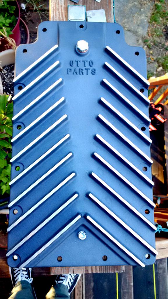 And here's the oil pickup installed: 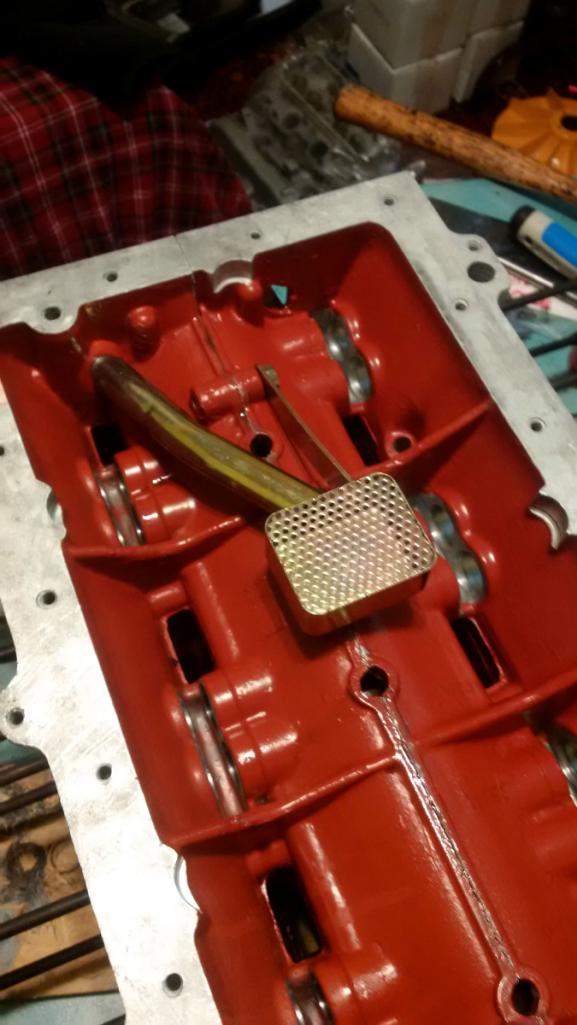 The Best Glass Tool of All Time: 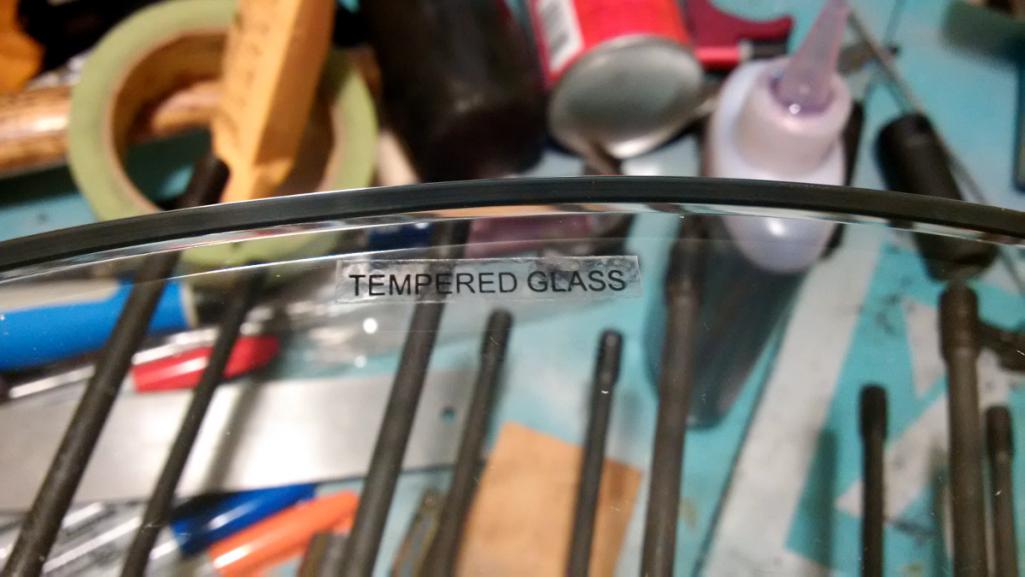 Here's checking the mating surface for flatness. Not pictured are the feeler gauges. 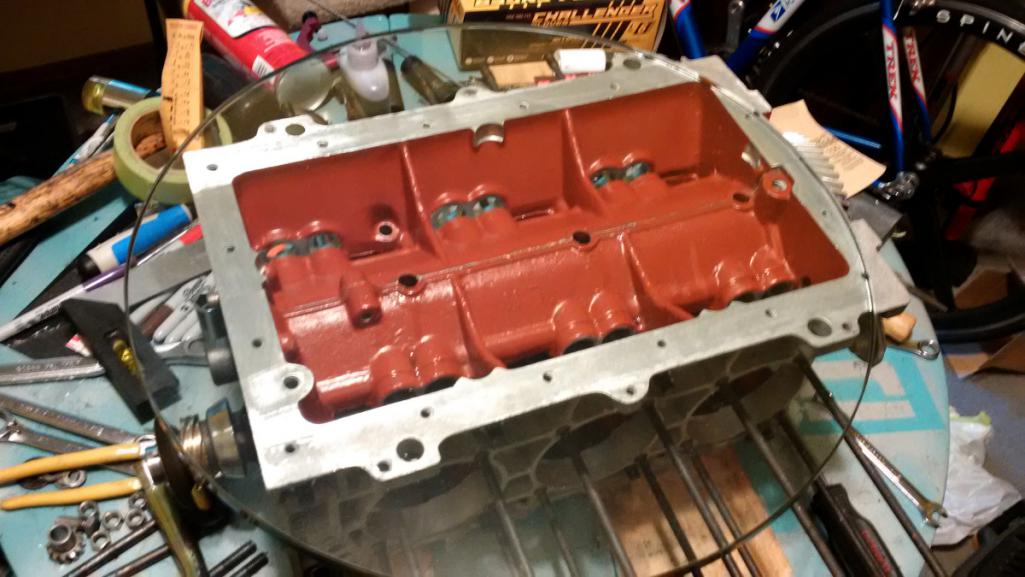 And here's a problem. I laid the oil pan onto the engine and it rocks something awful, like an 1/8" at the corner. At first I was freaked out thinking it might be the engine case. But it's not. Despite the beautiful machined finish of the oil pan mating surface, the trouble is indeed a manufacturing fault. I wrote a message to the vendor and hope to hear back from them tomorrow. Check it out: 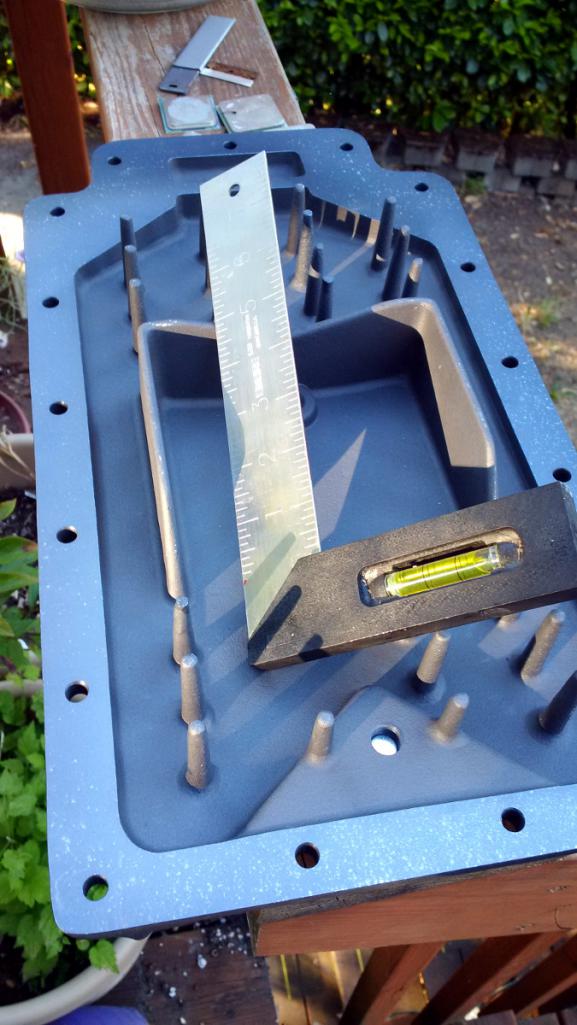 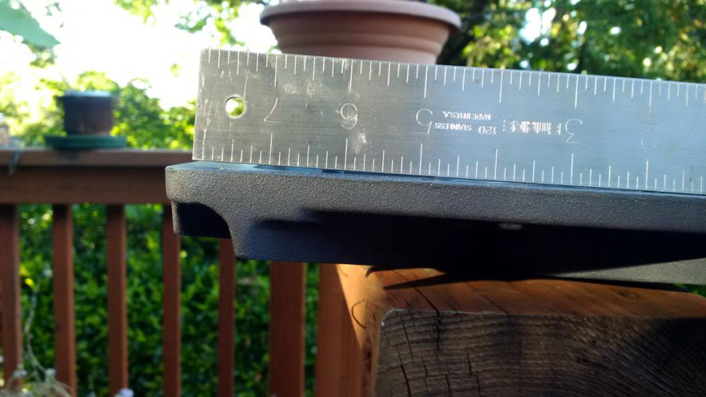 Yikes! That's not an easy bit of work to bolt onto a mill and re-surface. And even if I did I worry about the distance from the bottom of the oil pickup to the bottom of the oil pan. Hopefully it's not a big deal to get a better one. |
| r3dplanet |
 Jul 17 2017, 10:11 PM Jul 17 2017, 10:11 PM
Post
#163
|
|
Senior Member    Group: Members Posts: 679 Joined: 3-September 05 From: Portland, Oregon Member No.: 4,741 Region Association: None |
While the oil pan issue is getting resolved, I'm turning my attention to the [choose a noun] cover. The service manual calls it the "engine rear cover." But some people refer to it as just the rear cover, or the front cover, or the pulley cover (even though it doesn't cover the pulley), the distributor cover, the oil pump cover, etc. I'm going to call it The Cover of Many Uses.
Here's a front and rear view with some helpful labels: 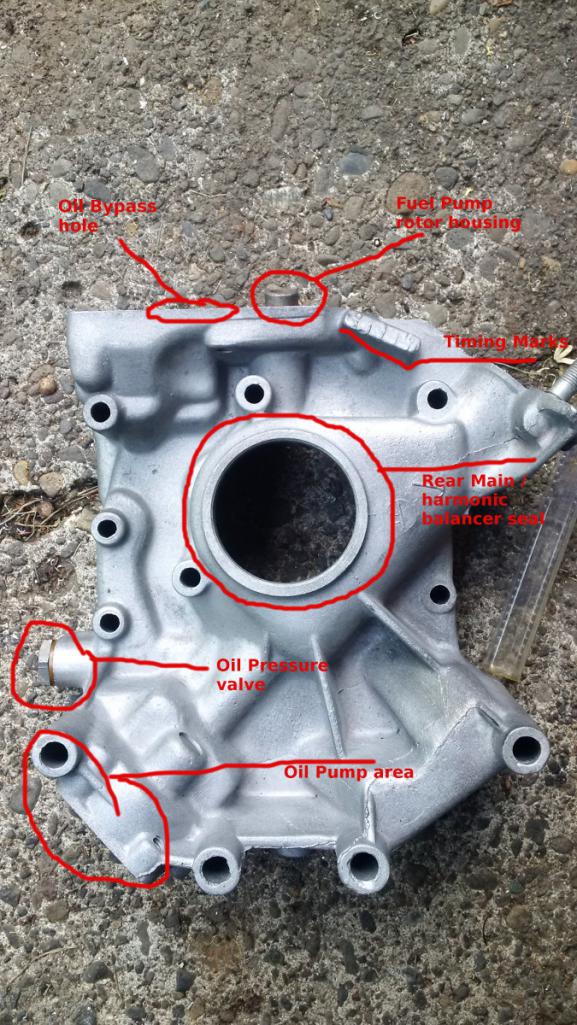 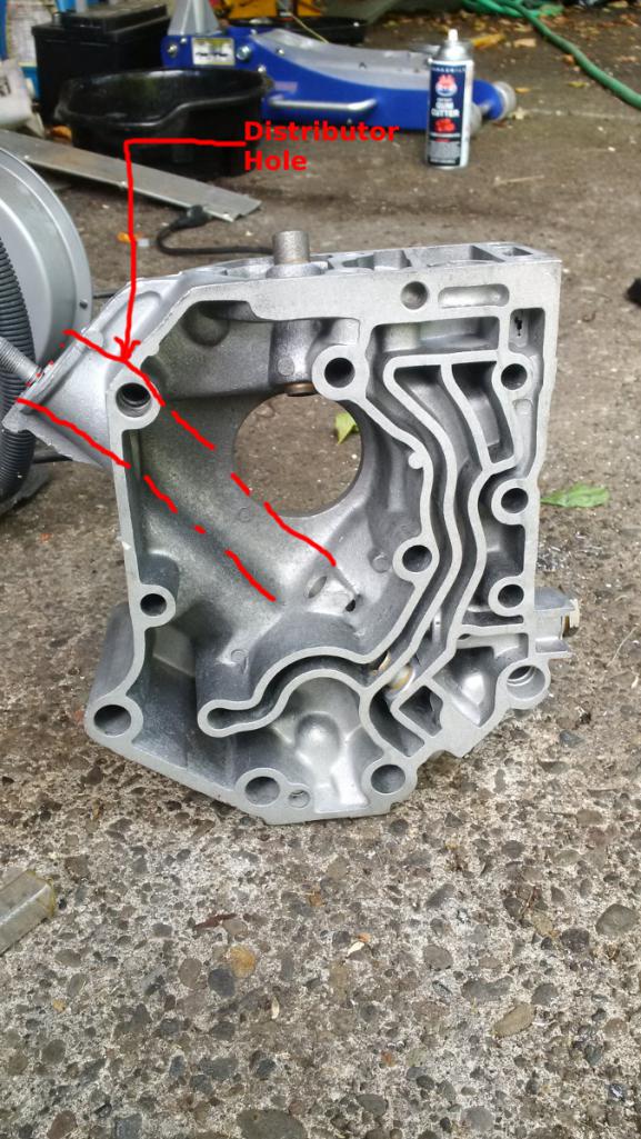 Here's something very important if you need to use a remote oil filter which is basically all 914 conversion adventurers. The stock oil filter needs to be cut off because it will try to occupy the same space as the firewall. So the oil filter neck is cut and threads tapped for hoses running to a remote oil filter. Don't do the following! Read on to Page 9 instead! What could be a problem is that unless the bypass valve isn't modified (plugged) in some way, then the valve will always be opened and the oil will never get filtered. That's bad. So I'm using an old racer's trick to plug the valve opening with a nickel. This will force all of the oil through the filter. This is not an original Red Planet Industries epiphany. It's been done a thousand times by builders and tinkerers before me. I didn't like the idea of using a nickel but I sorted through my huge glass jar of change and found a remarkably beaten nickel from 2014. If put back into circulation it would get pulled right away, so it became the candidate. The valve opening hole measured .802" on my cover, and that's not a measurement of a common object. So a nickel it was. I measured other coins I had also. A Mexican 50 cent coin works well, as does a 5 cent Euro coin, but the British £1 coin works best due to it's thickness. I just didn't want to spend a whole pound for this operation, and managed to save $1.26 in the process. The nickel needed to be filed down a bit before I popped it in, peened the edge, and filled the gap with good old JB-Weld. 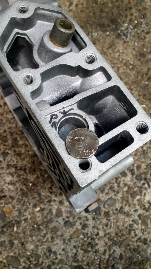 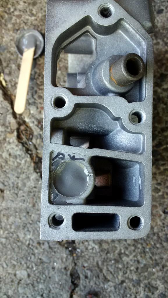 Still needed is the oil pressure valve bits (mine are worn) and the installation of the oil seal. I have the seal but the pressure valve bits are in the post. That's coming up... [i]in the future! |
| r3dplanet |
 Jun 3 2018, 12:39 AM Jun 3 2018, 12:39 AM
Post
#164
|
|
Senior Member    Group: Members Posts: 679 Joined: 3-September 05 From: Portland, Oregon Member No.: 4,741 Region Association: None |
It's Saturday night and I'm full of steroids so I decided to do some more work on the engine. Tonight's project was to get the piston rings measured and installed. I'm using the piston rings that came with the AA pistons for the first and third rings, but the second rings are "gapless" Total Seal rings. If I had to do this job again I'm not sure I'd bother using the Total Seal rings.
Here's the setting on my coffee table: 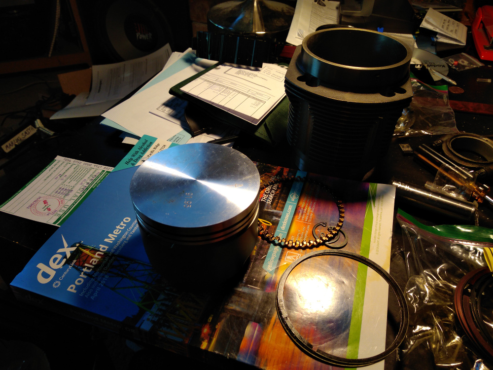 The first thing to do is to measure the gap in the empty space where the rings almost, but not quite, meet. I'm doing this for what amounts to five rings per cylinder x6 cylinders. In the past on other engines and parts, the gap is very often too small. I got lucky here and only had to file a couple of rings very gently. I'm using the rule of thumb that for every inch of bore, figure .0035 - .004. For 92mm (3.622 inches) I should aim for .013 - .015 thousandths. And I got exactly that. 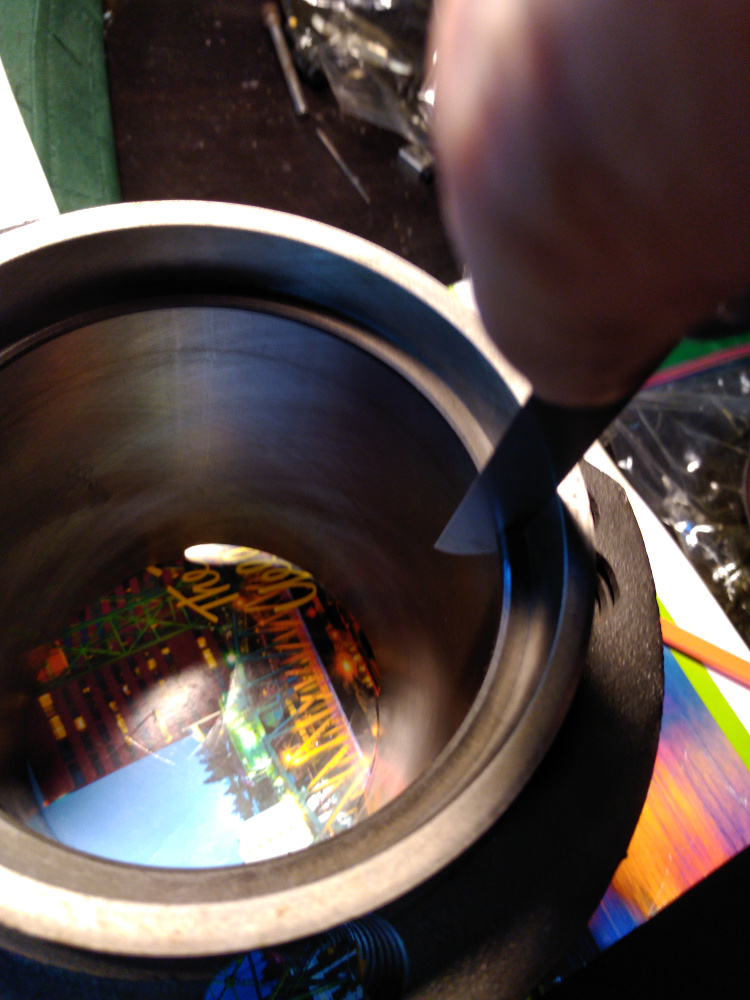 Starting with the rod side of the ring (or "bottom") the first ring to go is the accordion spacer ring. The ends butt against each other but do not overlap. This ring must go first before the other two that wedge on the upper and lower side. 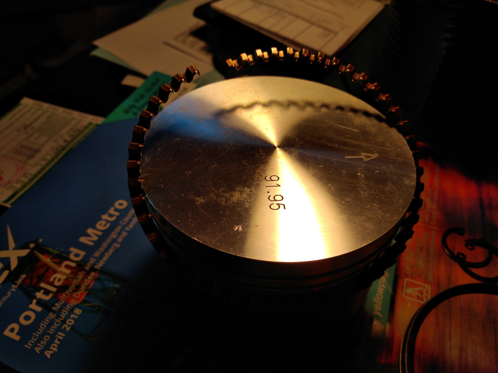 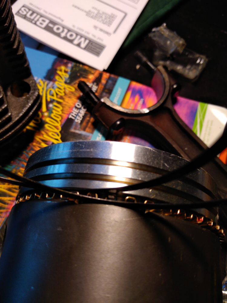 The Total Seal rings are a bit fiddly, and induce a vague sense of uneasiness. The instructions didn't seem to show my rings, but I snooped about online and found the orientation. First spiral on the larger ring, with the gap on the bottom. Then spiral on the very thin bottom ring into that gap. Gently squeezing around it seems to manage to work as one piece. I was careful to make sure the gaps of each ring were 180 degrees from each other. 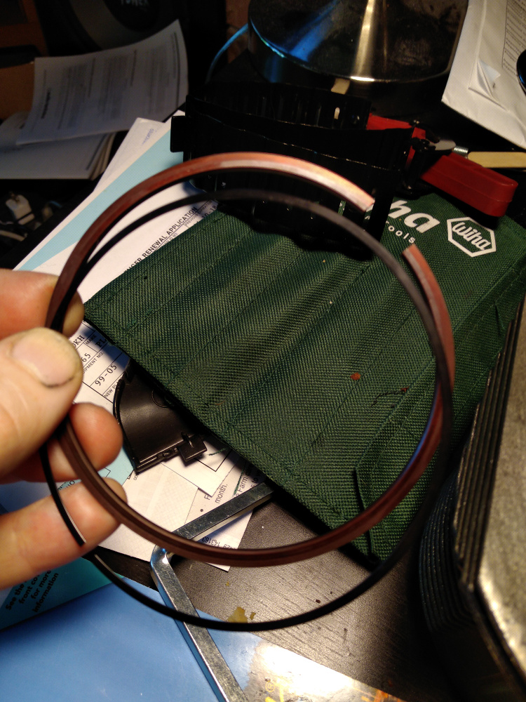 I'm just showing how the ring looks here. It actually installs upside down from what you see here. 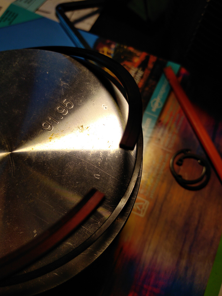 On the top ring you really have to look carefully for the "top" mark. Even a smear of oil hides the stamp. This one just spirals on like all the others. 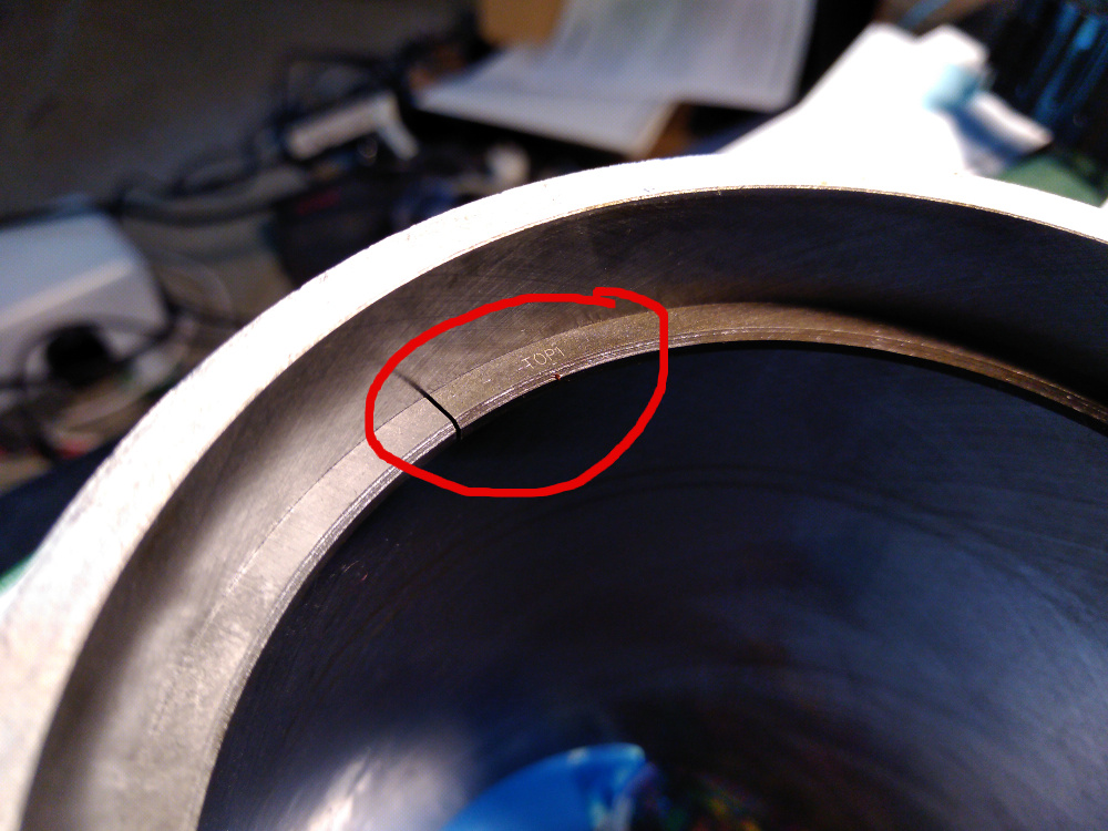 Now it's time to install the connecting rods. This can be done in two ways: first, assemble the piston, cylinder, connecting rods, and wristpins and then install the assembly into the block. Second, you could install the rods to the crankshaft and then install the pistons and cylinders and finally bork the wristpins in. I bumbled about both ways and decided on the first method. I really wish the Mahle wristpin clips were as easy as these circlips to install on my BMW R75/5. What a farking pain the Mahle clips are. Ugh. 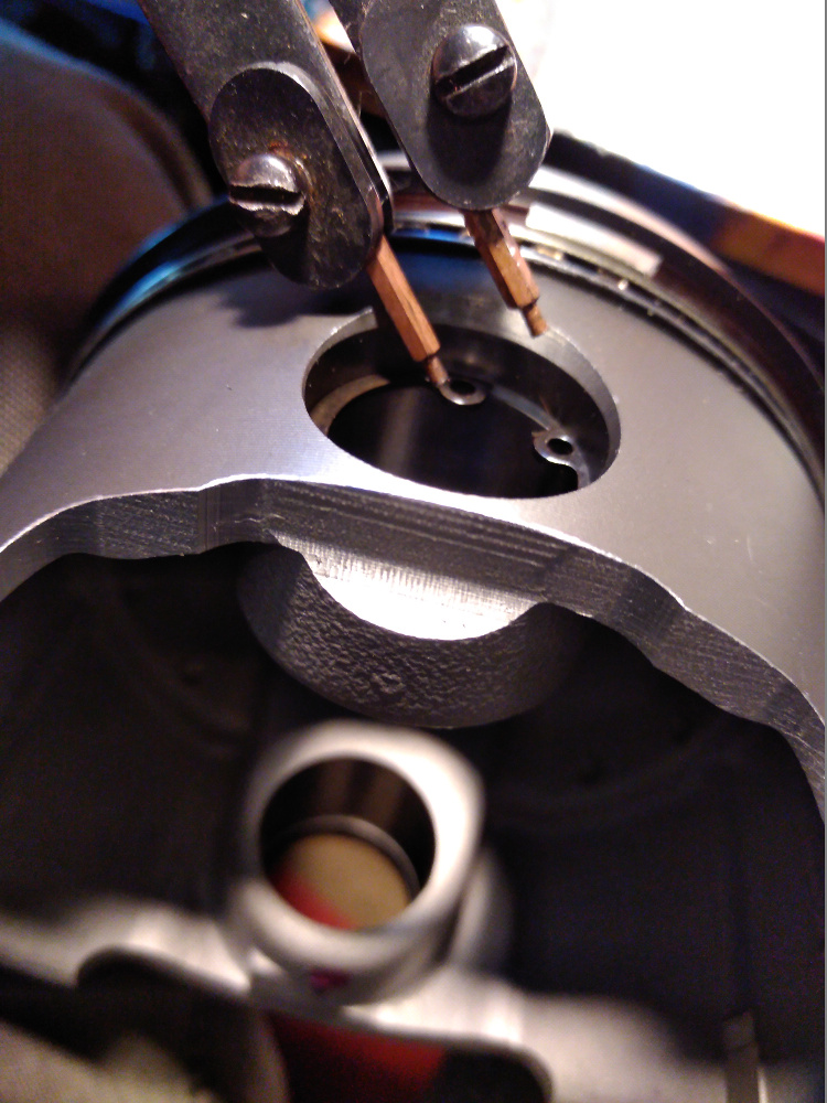 Here are three views of the left, center, and right side of the completed piston rings. Just for reference. I looked around online and never found the clarity I was looking for, so here it is. Not that I haven't spaced the ring gaps around the piston into their "final" position. This is just to highlight how the rings should fit. After this, I spaced them all 120 degrees or so from each other, making sure the 2nd Total Seal rings were 180 degrees apart. None of the gaps align with the wristpins. I honestly doubt this makes any difference as these rings will all spin about when the engine is running. 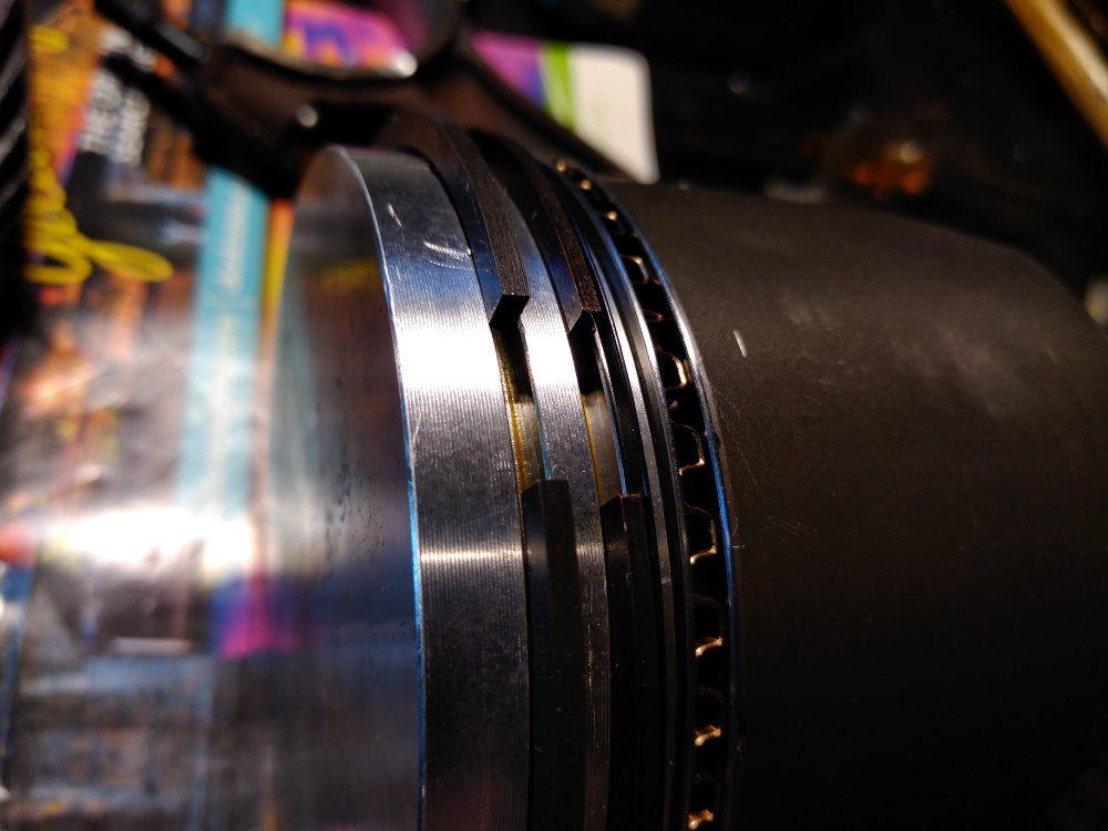 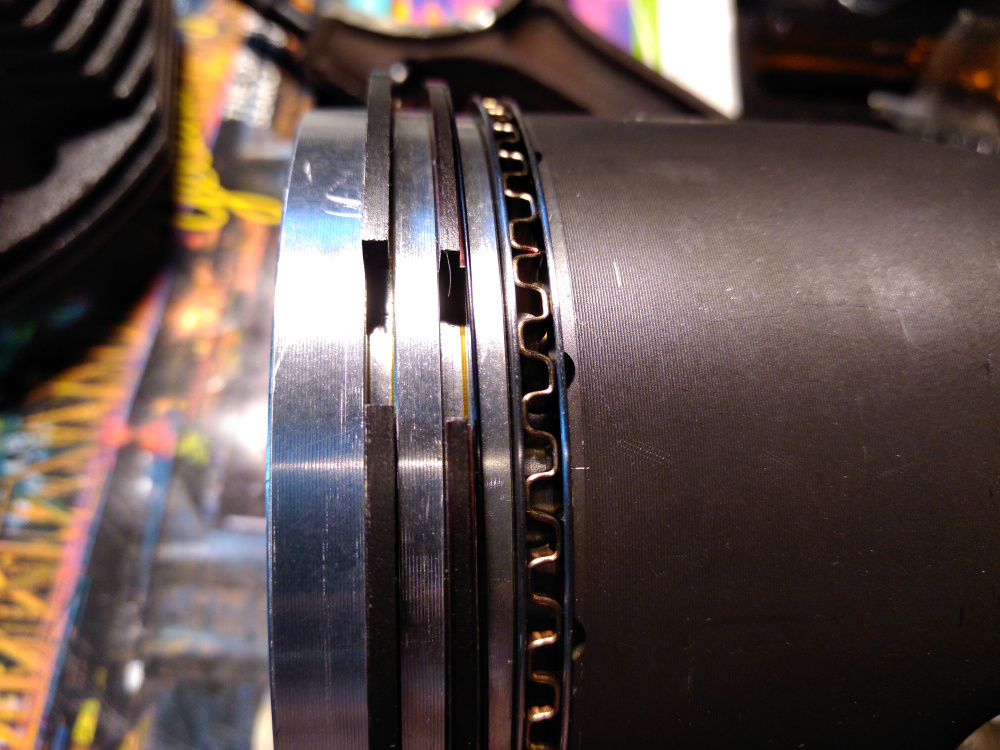 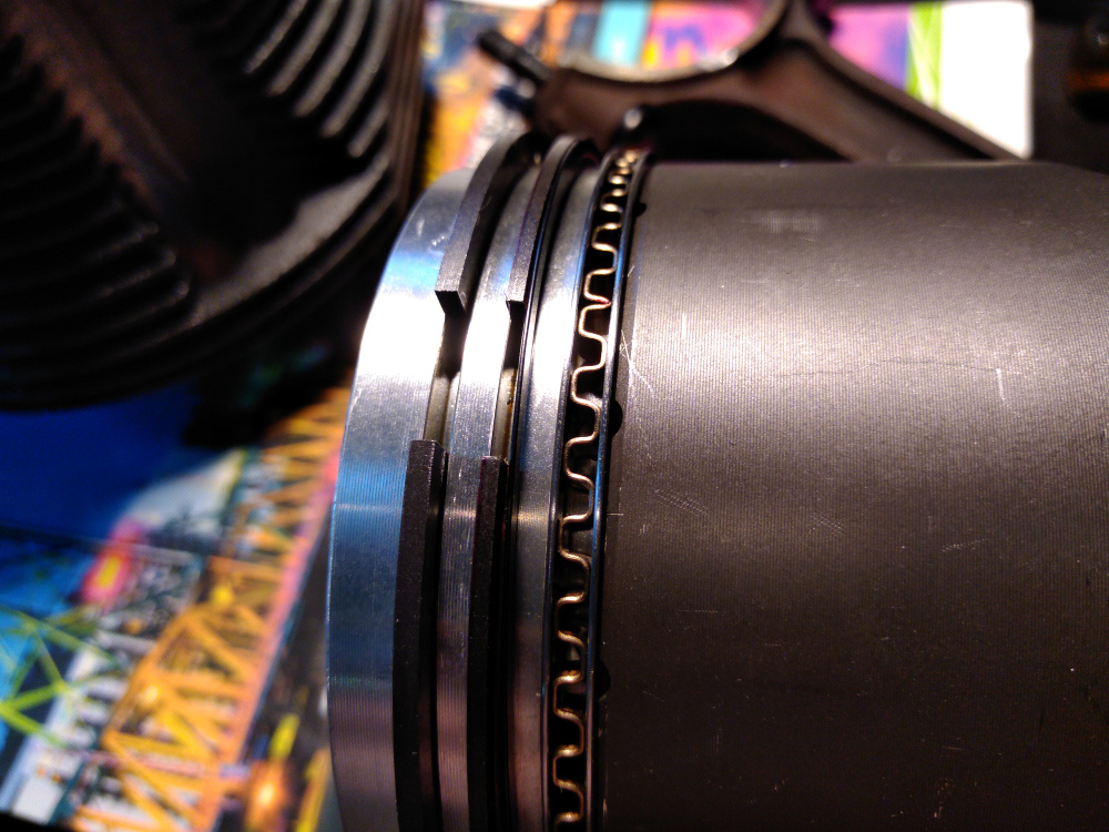 Last, here is the assembled piston and rod. Note the "#4" stamps on the big end at the bottom of the photo. This indicates that it's piston and rod #4 on the crankshaft. This stamp should point upwards, so it's legible looking down in from the top of the case. 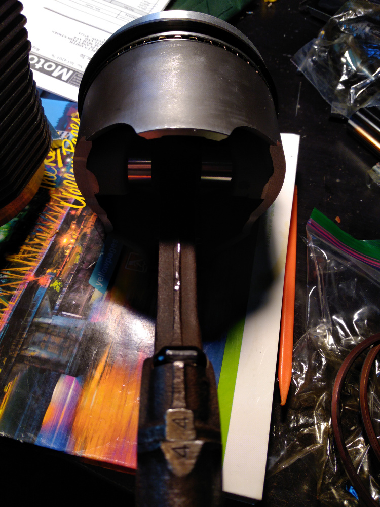 I assembled #3 and #4 first because I was worried about the clearance of the big end rotating inside the case. The head studs stick inside the case longer on these two registers and so I temporarily installed these two first and spun the crank to make sure. I have about 1/4" of clearance on each side. Not a lot of room, but it's enough. |
| r3dplanet |
 Jun 3 2018, 12:44 AM Jun 3 2018, 12:44 AM
Post
#165
|
|
Senior Member    Group: Members Posts: 679 Joined: 3-September 05 From: Portland, Oregon Member No.: 4,741 Region Association: None |
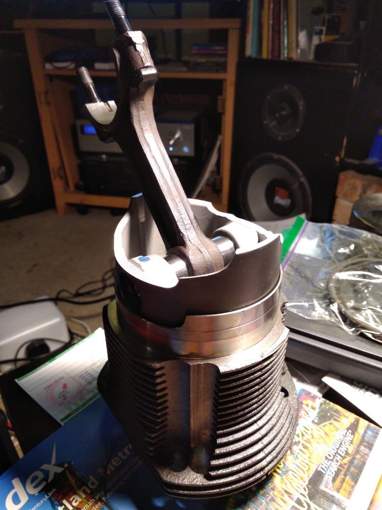
Oh right. Oops. Here's photo of the whole assembly:
 |
| JRust |
 Jun 3 2018, 10:51 AM Jun 3 2018, 10:51 AM
Post
#166
|
|
914 Guru      Group: Members Posts: 6,310 Joined: 10-January 03 From: Corvallis Oregon Member No.: 129 Region Association: Pacific Northwest 
|
Good to see you working on it Marcus. I know its been a long haul. Hope to see you at WCR this next weekend
|
| r3dplanet |
 Jun 26 2018, 11:32 PM Jun 26 2018, 11:32 PM
Post
#167
|
|
Senior Member    Group: Members Posts: 679 Joined: 3-September 05 From: Portland, Oregon Member No.: 4,741 Region Association: None |
I had to remove and install the cylinder assemblies a couple of times after my last entry. There was quite a bit of confusion as to which direction the pistons should point, and I ended up re-ringing every piston ring.
The conventional wisdom says that in a standard Corvair engine the pistons would normally point to the flywheel. Reverse rotation engines with stock Corvair cylinders have pistons that point toward the oil pump cover. But I couldn't find any info at all on which direction to point them if the engine is both reverse rotation AND has VW pistons and cylinders. I really do not want piston slap, but it may not be the end of the world if it happens. After consulting two engine builders who knew much about my project they said to point them toward the flywheel. So I did. Don't take this as gospel because it hasn't been tested yet. I failed to get a photo, but each piston skirt is clearanced right next to the wrist pin housing. This is because the big ends of the pistons rotate so closely to each other inside the case that the piston skirt will butt into the the opposing rod cap. In order allow the engine to spin, each piston is installed with the clearanced section facing the inside of the opposing piston. Then in order to make all of the pistons point the same way, each pair of opposing pistons was installed one pair at a time (#1 + #2, #3 + #4, and #5 + #6) allowing a full rotation of the crankshaft to ensure a nice spin. Also, the pistons and rod caps are numbered only on one side where the cap meets the small end. They MUST meet. One more time: THEY MUST MEET. But they don't have to point upward. That is, the numbers can face to either to top or bottom of the case so long as the numbers face each other. Here's #1: 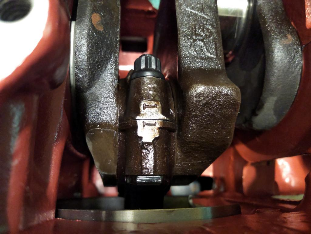 It happens that I had to flip two pistons and swap #5 and #3 to make it all fit correctly. No big deal. Just be aware. I found a problem with the prior piston ring clearances. At previous clearances, the engine just really struggled to spin. To correct that problem I removed all the rings and re-gapped them to .016" for the top ring and .019" for the second ring. I also ditched the Total Seal 2nd rings. One reason why is because I broke two of them, and I think they were the main contributors to the binding. Anyway, now all six are installed and it all spins nicely. Tight, but not too tight. 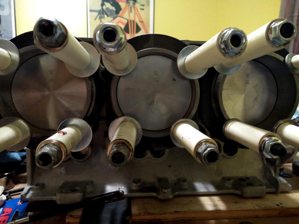 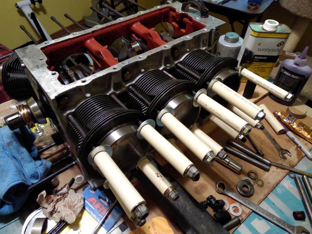 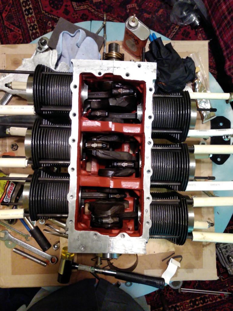 Now we can finally move on to the heads. Admittedly I had more trouble than I wanted, but I figured out all the trouble and rectified. The problem solving is enjoyable but thankfully it's moving faster and getting more fun. |
| r3dplanet |
 Jun 27 2018, 12:05 AM Jun 27 2018, 12:05 AM
Post
#168
|
|
Senior Member    Group: Members Posts: 679 Joined: 3-September 05 From: Portland, Oregon Member No.: 4,741 Region Association: None |
Let's have some fun with the heads.
Here's a photo of the valves along with the .040" copper head gaskets. Yes, the heads are filthy. Yes, they are clean now. 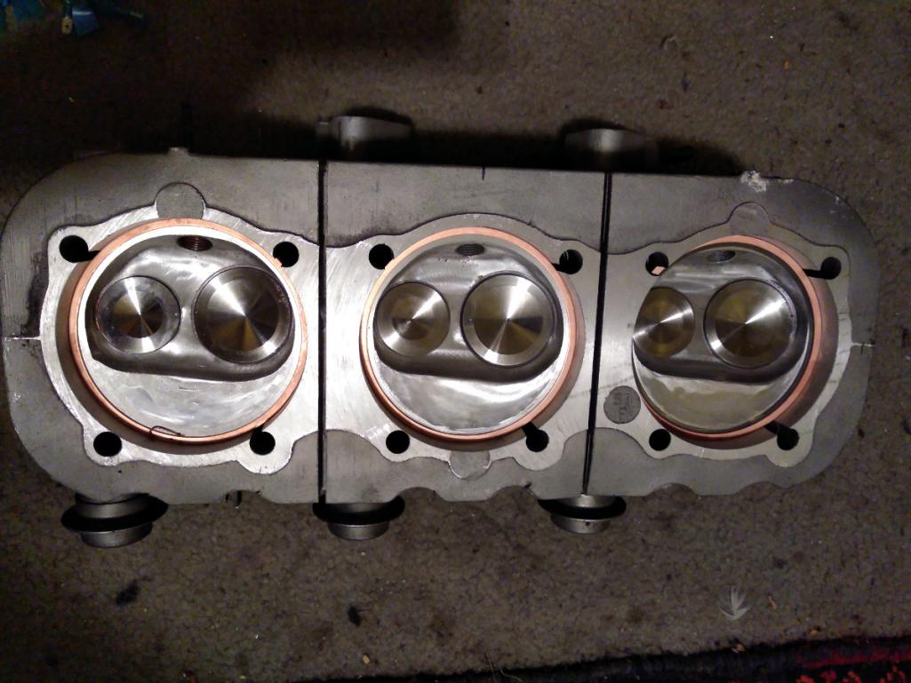 There are two things I want to do. First, I need to get a sense of the gap between the valves and the piston top. Second, I'd like to get the compression ratio together. Using the tried and true Play-Doh method, I shoved a bunch of Doh into the combustion chamber and trial fitted one of the cylinder heads and torqued it down. The idea is to get a physical mold of the valve impression and then carefully measure the thickness of the squished Doh. 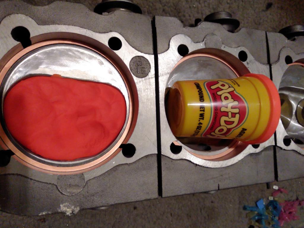 Note that I'm using .010" base gaskets (actually .0118") with a thin smear of copper RTV on the base gaskets. That plus the .040" copper head gaskets (well, .0386") I should have the correct .050" overall head gasket thickness. I fitted two solid lifters into the corresponding bores along with the stock pushrods and gave the engine two turns. I took it apart and realized I made the mistake of not using enough Doh, so I did it again. Ideal clearance is between .35"-.40", and mine measure .371". Crazy impressive and totally not my doing. That's the work of Tom Knoblauch who did the machine work on the cylinders, pistons, and elsewhere. Now that I know how to appreciate such things, I'm super appreciative! 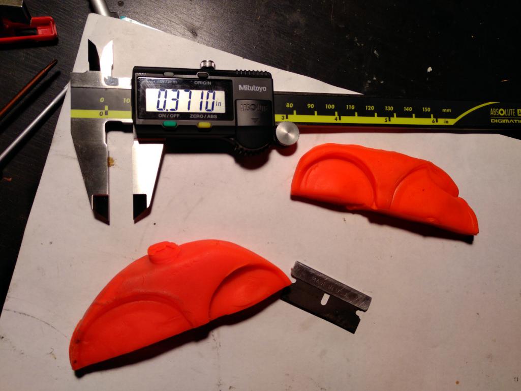 Then I realized that it was way too early to be doing this measurement because I'm not using stock pushrods or rockers. Oops. More on that later. While I'm waiting for some parts to arrive, let's measure the volume of the combustion chamber. This is a well known method that I see all the time. It's not triple accurate, but it's good enough. I bought an acrylic plastic circle of 3-15/16" diameter and drilled two holes. One to fill with liquid, the other to capture and release air bubbles. I'm using Water Wetter because it has good contrast and low surface tension. I'm sure you have all seen this a million times before. I had to do this process a number of times either because I had bubble trouble or just sloppy technique. But the result is an average of 51cc from all three chambers. They were actually dead nuts accurate as far as my testing ability goes. 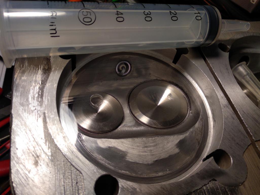 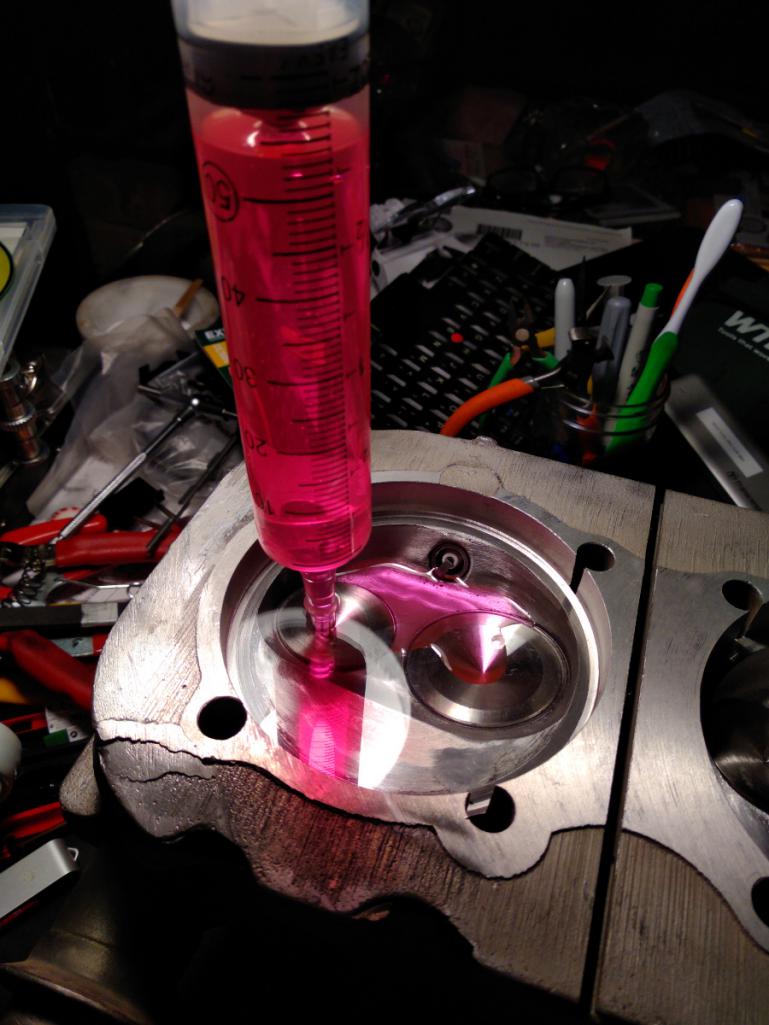 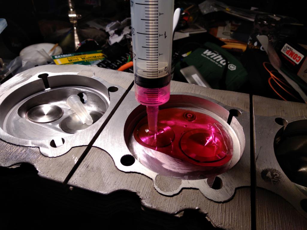 Running the info through various online calculators shows that I have a 9.35:1 compression ratio. Nifty. That's very close to the factory 9.25:1 ratio, and not enough to bother with using thicker gaskets to compensate. If anyone cares, here's the data: Bore: 92mm Stroke: 2.94" Deck height: 0 Piston dome/dish: 0 Chamber volume: 51cc Number of cylinders: 6 Compressed gasket thickness: .050" = 9.35:1 I hope that whoever ends up with the engine will be good enough to use high octane non-ethanol fuel, as a gentleman always should. |
| Porschef |
 Jun 27 2018, 04:23 AM Jun 27 2018, 04:23 AM
Post
#169
|
|
How you doin'     Group: Members Posts: 2,180 Joined: 7-September 10 From: LawnGuyland Member No.: 12,152 Region Association: North East States 
|
(IMG:style_emoticons/default/beerchug.gif)
Cool stuff, and hopefully a little diversion from the not cool stuff. |
| DaveO90s4 |
 Jun 28 2018, 03:16 AM Jun 28 2018, 03:16 AM
Post
#170
|
|
Member   Group: Members Posts: 149 Joined: 26-April 16 From: Australia Member No.: 19,935 Region Association: None |
Hi Marcus - great to read about your progress.
Are you still going to use the spring loaded idler? I was strongly advised not to on my reverse rotation engine - the pulley being on the 'pull' side of the crank and that tension overpowering the spring etc. on my engine all is working well with the standard set up. And you say above "whoever gets this engine" - are you not going to put it into your 914 after all? Feel free to email me any time - I think you'll still have my email address. Cheers DaveO |
| r3dplanet |
 Jun 28 2018, 12:05 PM Jun 28 2018, 12:05 PM
Post
#171
|
|
Senior Member    Group: Members Posts: 679 Joined: 3-September 05 From: Portland, Oregon Member No.: 4,741 Region Association: None |
You know, that's a really great question. I had intended to use it right up until you mentioned this. I thought that whole point behind the spring loaded idler was to prevent belt failure on reverse rotation engines. Hmm..
|
| 1adam12 |
 Jun 28 2018, 02:10 PM Jun 28 2018, 02:10 PM
Post
#172
|
|
Member   Group: Members Posts: 209 Joined: 25-May 17 From: Chino Hills, CA Member No.: 21,132 Region Association: Southern California |
Your progress is looking great Marcus. I was contemplating this swap a few months ago but sticking with the flat4. I even had a talk with California Corsairs which is right down the street from me. They had blocks stacked up to the ceiling there!
Here's some inspiration for ya from some shop images I took from there... Attached image(s) 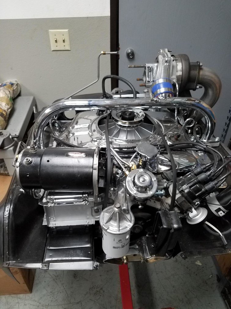 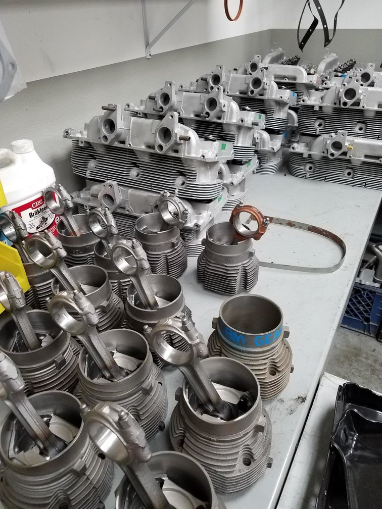
|
| r3dplanet |
 Jun 28 2018, 02:12 PM Jun 28 2018, 02:12 PM
Post
#173
|
|
Senior Member    Group: Members Posts: 679 Joined: 3-September 05 From: Portland, Oregon Member No.: 4,741 Region Association: None |
Ha! Look at all that! Very cool! Maybe I should drop the compression and add a turbo.
|
| DaveO90s4 |
 Jun 28 2018, 03:41 PM Jun 28 2018, 03:41 PM
Post
#174
|
|
Member   Group: Members Posts: 149 Joined: 26-April 16 From: Australia Member No.: 19,935 Region Association: None |
Hi Marcus,
Have a close look at the generator cooling blades on the photo that Adam posted. Vairy interesting indeed methinks. What to infer from that? DaveO |
| r3dplanet |
 Jun 28 2018, 09:50 PM Jun 28 2018, 09:50 PM
Post
#175
|
|
Senior Member    Group: Members Posts: 679 Joined: 3-September 05 From: Portland, Oregon Member No.: 4,741 Region Association: None |
Yeah, right? That's a reverse rotation alternator fan on a stock generator that doesn't spin backwards. Interesting. Maybe someone rebuilt the generator into an alternator?
|
| r3dplanet |
 Jun 28 2018, 10:09 PM Jun 28 2018, 10:09 PM
Post
#176
|
|
Senior Member    Group: Members Posts: 679 Joined: 3-September 05 From: Portland, Oregon Member No.: 4,741 Region Association: None |
More progress today and it's all about vanity. I pulled out the powder coating gear and coated some things. Also made an unpleasant discovery along the way. The long block is getting about finished but on pause due to some more head gaskets on order. Plus it was a nice day and I didn't have to spend it connected to a medical probe-u-lator.
Most of the parts are cast aluminum and so really don't need to be prettied. Nobody will see them. Eh. Because they're cast they cannot be anodized so powder it is. First up, the engine cover / fan housing got some treatment with a little file to remove a million little casting boogers. I wish I would have taken the extra time to polish the whole cover because it didn't turn out super in the end. But it's nice enough. Actually, I wish GM had done a better job and polished it but.. eh. 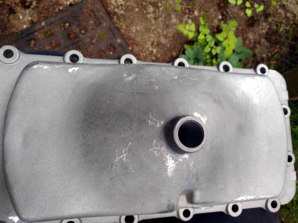 This is the largest piece I've ever put into my little bench top oven and it barely squeaked in. I put together some alumin(i)um mounts to move it about without bothering the powder. More machine gray. 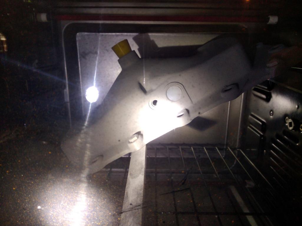 Then it was off to do the dipstick tube and oil filler cover. Here's the unpleasant discovery. It's full of what I think are glass beads from the blasting process from the guy on eBay from whom I purchased it. This would have a been a super quick way to kill the engine if assembled this way. This sort of thing drives me nuts, bananas, crackers, or any other snack food euphemism one cares to invent. I pulled out the rotary tool and polished it's innards and then cleaned it with mineral spirits and a brush. Took five minutes. I can't understand the mind of the seller who couldn't be bothered. Just a little quality control could save an engine. I'll be he has worms in his brain. It wasn't obvious as the oil pump pressure plunger was already installed. Unless I took steps to remove it for inspection it would have made for a really bad outcome. 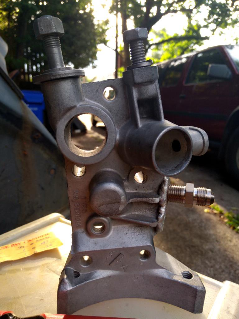 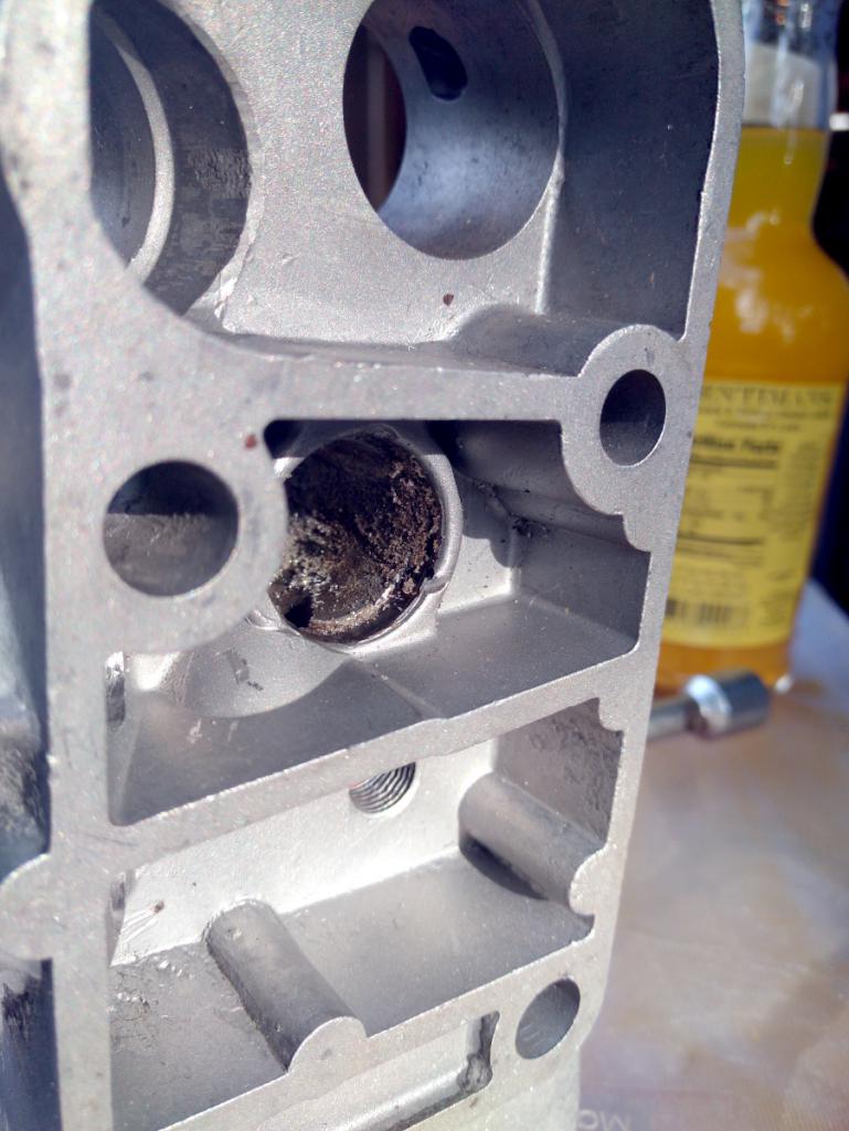 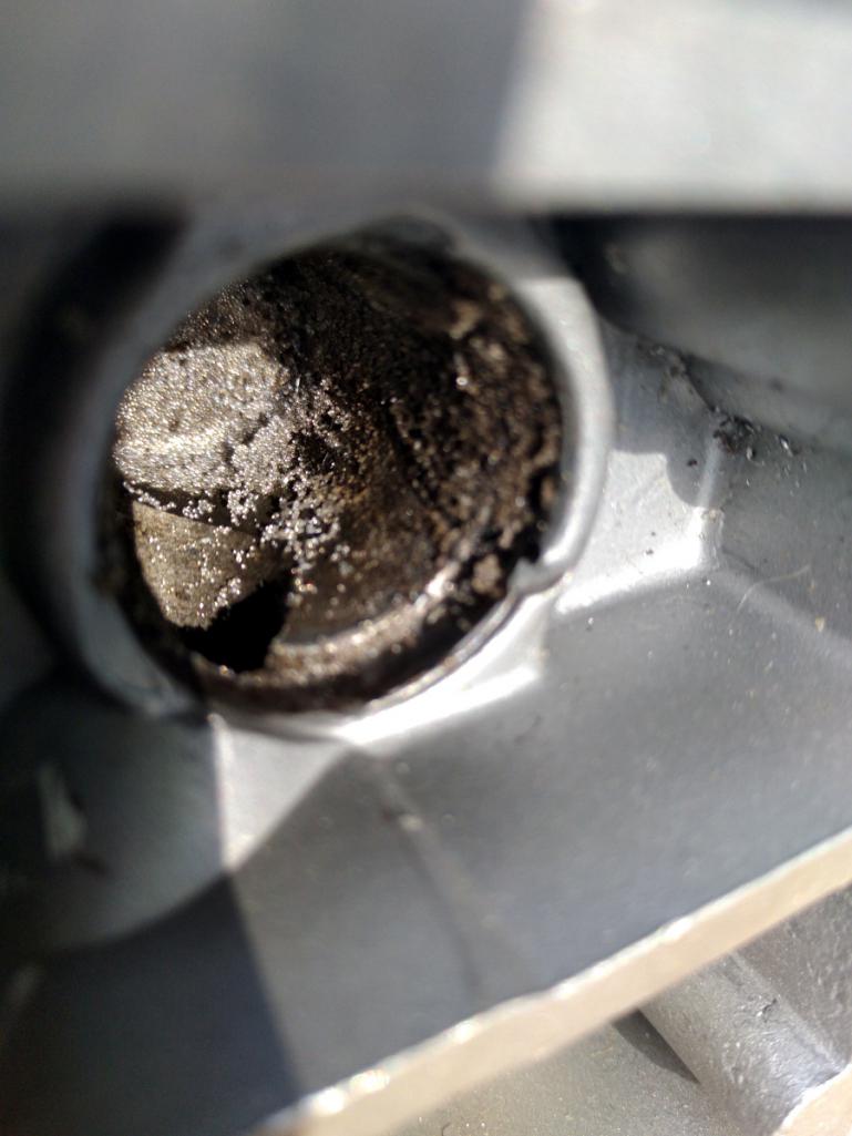 I didn't get any photos of the Cover of So Many Uses but it was coated also. So are the pushrod tubes but I did those with high-temp silver and then polished the business ends. It's traditional to paint them white, and I may yet for No Good Reason. The day's tally: 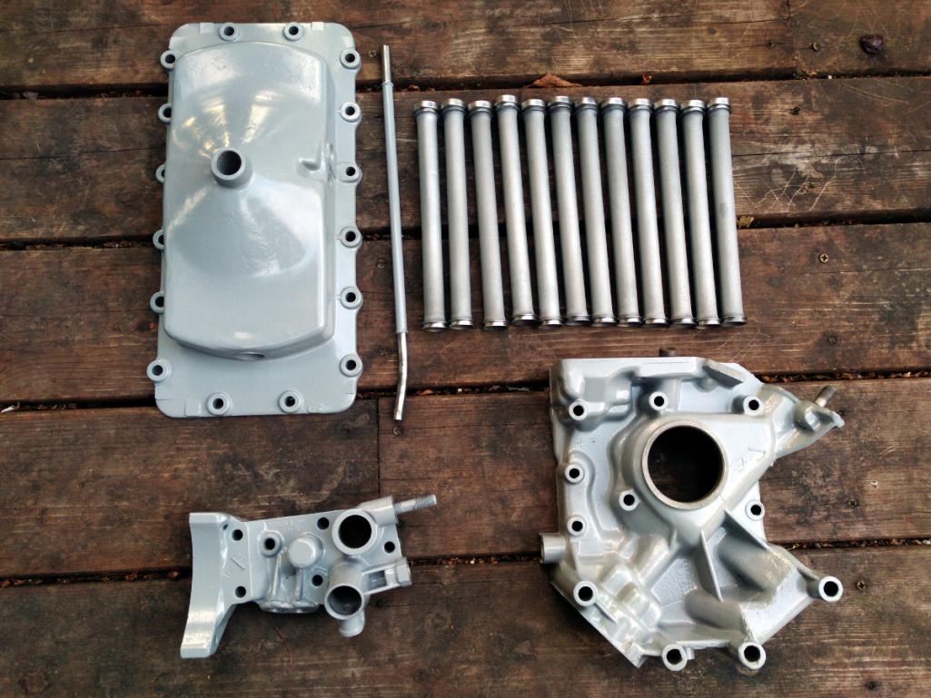 |
| r3dplanet |
 Jun 28 2018, 10:13 PM Jun 28 2018, 10:13 PM
Post
#177
|
|
Senior Member    Group: Members Posts: 679 Joined: 3-September 05 From: Portland, Oregon Member No.: 4,741 Region Association: None |
I'll be installing the pushrod tubes very shortly. There are twelve of them of course. Thinking about the concept of "twelve" today brought this to mind:
https://www.youtube.com/watch?v=VOaZbaPzdsk |
| worn |
 Jun 28 2018, 10:29 PM Jun 28 2018, 10:29 PM
Post
#178
|
|
can't remember     Group: Members Posts: 3,342 Joined: 3-June 11 From: Madison, WI Member No.: 13,152 Region Association: Upper MidWest 
|
Yeah, right? That's a reverse rotation alternator fan on a stock generator that doesn't spin backwards. Interesting. Maybe someone rebuilt the generator into an alternator? Sure looks great! Your posts show a lot of detail. In reference to the blingish images above, which way does that belt turn in a stock motor? Sorry to be so simple about these. Rode in a new one once upon a time but know so little. |
| r3dplanet |
 Jun 28 2018, 11:00 PM Jun 28 2018, 11:00 PM
Post
#179
|
|
Senior Member    Group: Members Posts: 679 Joined: 3-September 05 From: Portland, Oregon Member No.: 4,741 Region Association: None |
Good question. I've hardly thought about it until now. If you scroll up and look at the engine photo posted by 1adam12, have a look at the big fan in the middle. On a stock engine it will rotate clockwise. Naturally in a reverse rotation engine the fan spins counterclockwise. That has historically caused trouble with throwing belts. I'm going to have to investigate this when the time comes. DaveO90s4 knows more than I do.
Yeah, right? That's a reverse rotation alternator fan on a stock generator that doesn't spin backwards. Interesting. Maybe someone rebuilt the generator into an alternator? Sure looks great! Your posts show a lot of detail. In reference to the blingish images above, which way does that belt turn in a stock motor? Sorry to be so simple about these. Rode in a new one once upon a time but know so little. |
| r3dplanet |
 Jun 28 2018, 11:12 PM Jun 28 2018, 11:12 PM
Post
#180
|
|
Senior Member    Group: Members Posts: 679 Joined: 3-September 05 From: Portland, Oregon Member No.: 4,741 Region Association: None |
A little follow-up from the previous modification where a nickel was stuffed into the oil bypass hole. After third thoughts and some social confirmation, there's really no reason to do this. So it's time to free Thomas Jefferson.
Torches and digging: 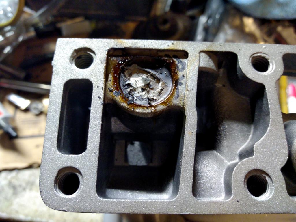 Tom looks pissed. He has every right to be. I feel bad because I always liked the guy. Except the slavery part. You can just see the disappointment on his face, "Marcus! Get me out of this damn hole!" 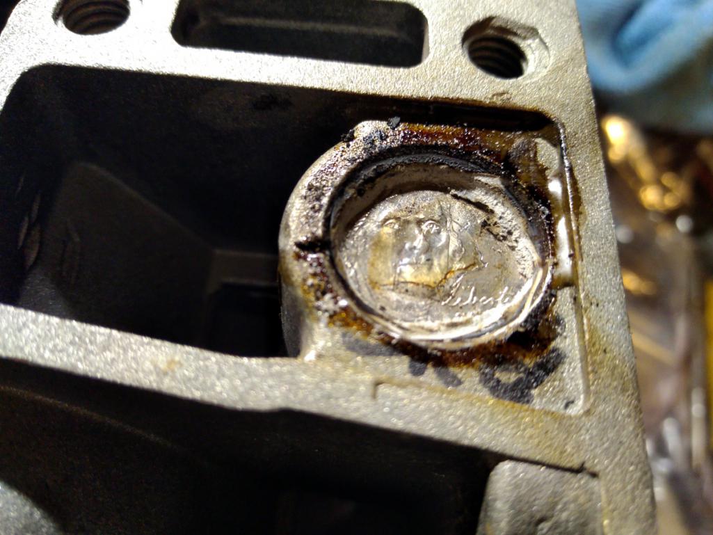 Now I have a perfectly good nickel. 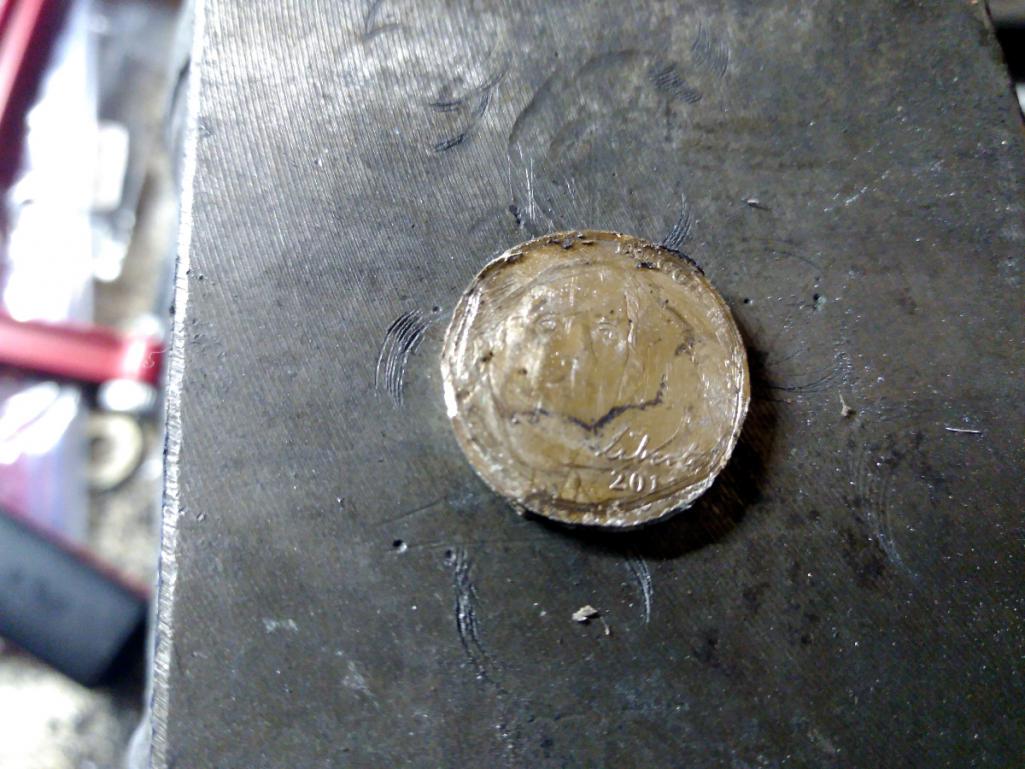 And finally a little cleanup. Good as new. 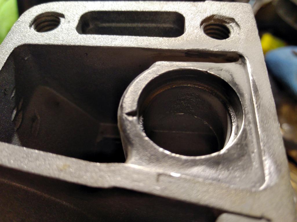 |
  |
1 User(s) are reading this topic (1 Guests and 0 Anonymous Users)
0 Members:

|
Lo-Fi Version | Time is now: 23rd November 2024 - 03:23 PM |
Invision Power Board
v9.1.4 © 2024 IPS, Inc.


