|
|

|
Porsche, and the Porsche crest are registered trademarks of Dr. Ing. h.c. F. Porsche AG.
This site is not affiliated with Porsche in any way. Its only purpose is to provide an online forum for car enthusiasts. All other trademarks are property of their respective owners. |
|
|
  |
| DaveO90s4 |
 Jun 29 2018, 02:09 AM Jun 29 2018, 02:09 AM
Post
#181
|
|
Member   Group: Members Posts: 149 Joined: 26-April 16 From: Australia Member No.: 19,935 Region Association: None |
I think Marcus meant to say:-
Good question. I've hardly thought about it until now. If you scroll up and look at the engine photo posted by 1adam12, have a look at the big fan in the middle. On a stock engine it will rotate counterclockwise. Naturally in a reverse rotation engine the fan spins clockwise. (In a normal Corvair engine the crank will pull the fan belt from the horizontal fan via the alternator pulley. Thus the alternator is on the tensioned side of the belt. With a reverse rotation engine the alternator is of course on the less tensioned part of the belt travel) |
| Tbrown4x4 |
 Jun 29 2018, 02:50 AM Jun 29 2018, 02:50 AM
Post
#182
|
|
Senior Member    Group: Members Posts: 706 Joined: 13-May 14 From: Port Orchard, WA Member No.: 17,338 Region Association: None 
|
. It's traditional to paint them white, and I may yet for No Good Reason. Traditionally, the white paint is VHT high temp, and is only used on the tube end closest to the exhaust stub. This helps prevent the exhaust heat from transferring to the o-ring on that end and to the oil draining through the tube. The tube also helps dissipate heat from the oil, so the opposite end of the tube stays unpainted (or only lightly painted). |
| r3dplanet |
 Jun 29 2018, 12:26 PM Jun 29 2018, 12:26 PM
Post
#183
|
|
Senior Member    Group: Members Posts: 679 Joined: 3-September 05 From: Portland, Oregon Member No.: 4,741 Region Association: None |
Thanks! That's good to know. I'll make the modification to mine today.
. It's traditional to paint them white, and I may yet for No Good Reason. Traditionally, the white paint is VHT high temp, and is only used on the tube end closest to the exhaust stub. This helps prevent the exhaust heat from transferring to the o-ring on that end and to the oil draining through the tube. The tube also helps dissipate heat from the oil, so the opposite end of the tube stays unpainted (or only lightly painted). |
| r3dplanet |
 Jun 29 2018, 10:56 PM Jun 29 2018, 10:56 PM
Post
#184
|
|
Senior Member    Group: Members Posts: 679 Joined: 3-September 05 From: Portland, Oregon Member No.: 4,741 Region Association: None |
Today just had enough room in it to put together the cooling fan bearing assembly.
I bought a bearing and polished aluminum housing and then squished them into place. On the subject, does anyone want my old Snap-On hydraulic press? It disassembles, which is nice, because it stands seven feet tall. It needs plenty of love but if anyone wants to come and get it they can have it for nothing. Here's the pressed bearing and housing. 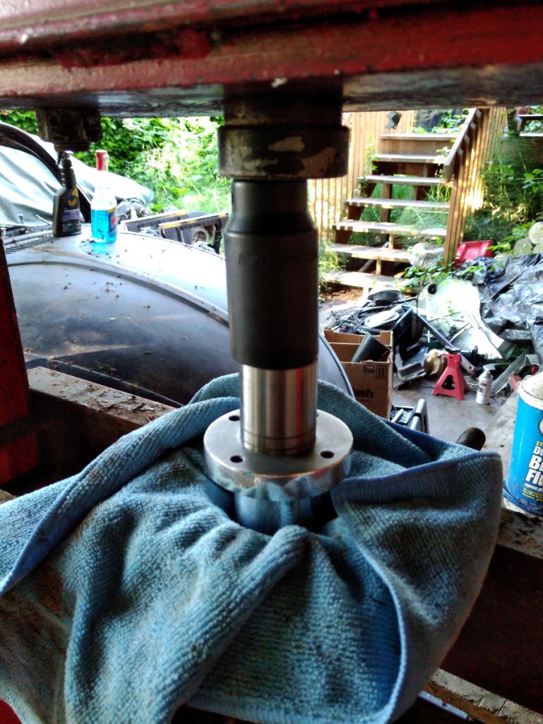 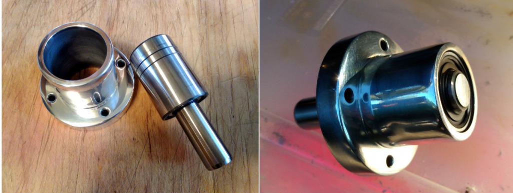 Then the tricky bit. It may not seem like it but pressing the bearing shaft into the engine top cover needs to be a precise exercise. The distance from the deck to the top outer diameter of the bearing needs to be between 4.46"-4.49". The idea is that when assembled there is a critical gap distance between the fan blades and the engine cover. Too close and it will make contact and be sad, too far and the forced air won't make enough pressure to cool the engine. I spent quite a lot of time trying to get this just right. If you ever do this, I think the easier measurement is the gap between the bottom of the bearing housing and the top of the fan cover, which is .040". Yes, I know the powder coating looks crappy. 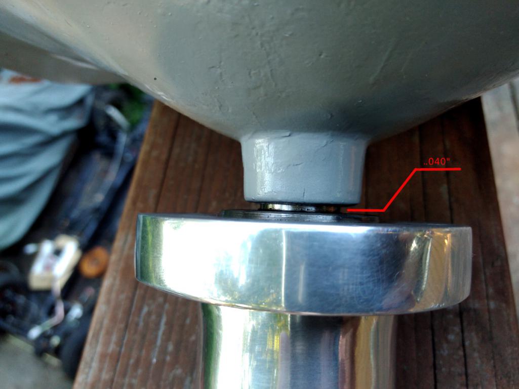 I still need to find the fan-to-cover measurement, the one that really matters. I'll find it and report back. With gaskets in place it looks to be 1/4". Here's what it looks like mocked up with the bearing, fan, pulley, and cover. 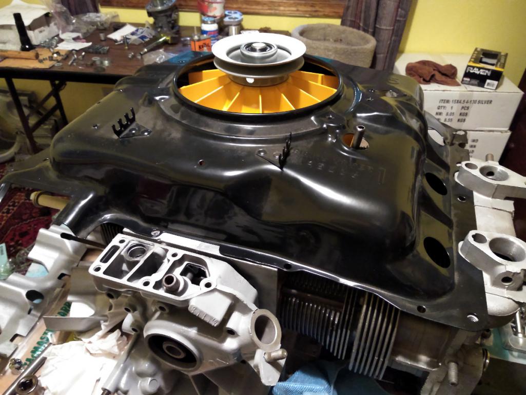 You might be thinking, "Marcus, the orange looks terrible. Your color sense is lacking and your sensibilities are crude." And you be right. I coated the fan to match the car, but now it looks loud and out of place. Oh well. Orange it is. I happen to like orange a lot but I get your point. On the subject of fans, here's the vertical fan setup I drool over. I think it would look much more at home in the 914. I want one more than I want my next breath. Feast your pupils: http://americanflat6.com/products/verticalfans.html |
| DaveO90s4 |
 Jun 30 2018, 06:01 AM Jun 30 2018, 06:01 AM
Post
#185
|
|
Member   Group: Members Posts: 149 Joined: 26-April 16 From: Australia Member No.: 19,935 Region Association: None |
Dear Marcus, re vertical fans. I very very respectfully disagree:-). Vertical fans are just oh so passé. Every 914-6 has them. The horizontal fan is - in a 914 - pretty unusual.
And the horizontal fan works. And there is damn allclearance in that area too in a 914-C6. What with the crank pulley very close to the firewall, the firewall sloping back into the engine bay as it rises, the air restriction into the fan and the difficult tight turn the air has to take to get into the fan aperture. Plus how to top er up with oil? And how to readily accesss the Cover of Infinite Uses? I'm inclined to think for normal road use it is a solution to a problem that does not exist. (Note: all above comments with respect to Corvair engine in 914. I make no comment re clearance etc for Porsche engine in 914 engine bay) And I like the orange fan too:-) Cheers DaveO |
| r3dplanet |
 Jun 30 2018, 11:26 AM Jun 30 2018, 11:26 AM
Post
#186
|
|
Senior Member    Group: Members Posts: 679 Joined: 3-September 05 From: Portland, Oregon Member No.: 4,741 Region Association: None |
Geez, is pragmatism all you have to offer?
Dear Marcus, re vertical fans. I very very respectfully disagree:-). Vertical fans are just oh so passé. Every 914-6 has them. The horizontal fan is - in a 914 - pretty unusual. And the horizontal fan works. And there is damn allclearance in that area too in a 914-C6. What with the crank pulley very close to the firewall, the firewall sloping back into the engine bay as it rises, the air restriction into the fan and the difficult tight turn the air has to take to get into the fan aperture. Plus how to top er up with oil? And how to readily accesss the Cover of Infinite Uses? I'm inclined to think for normal road use it is a solution to a problem that does not exist. (Note: all above comments with respect to Corvair engine in 914. I make no comment re clearance etc for Porsche engine in 914 engine bay) And I like the orange fan too:-) Cheers DaveO |
| r3dplanet |
 Jul 1 2018, 11:37 PM Jul 1 2018, 11:37 PM
Post
#187
|
|
Senior Member    Group: Members Posts: 679 Joined: 3-September 05 From: Portland, Oregon Member No.: 4,741 Region Association: None |
There's a bit to know about rocker arms if you ever take this path and build your own engine. The stock rockers are just fine for a stock engine. They are made of stamped, hardened steel. The business end of it slides along a fixed radius, keeping in contact with the valve stem at all times. But there two undesirable characteristics. First, they can be inconsistent with one another and may not be suitable for big bore engines. Second, all that friction creates a lot of unnecessary heat.
To rectify this you can go with a full roller setup, but that is expensive for the set that Clark's sells, or you can spend even more and get a bespoke roller cam and lifter combo. The rollers do away with the stock girdles (pushrod keepers) and use a larger, rigid bar instead. Also required are longer, stronger ARP studs and bigger valve covers. Some vendors use lovely but lousy Chinese-made rollers that blow apart rapidly. These are the ones that Dr. Evil put into his bus engine. I was very tempted to buy them as well but quickly walked away after Dr. Evil's unwelcome experience. If you look through Corvair forums you'll see that this particular product has lots of similar failures. A whole roller set wasn't in my budget so I'm going with the next best thing - small block Ford roller tip rockers manufactured by Comp Cams. These are also used in some Olds models. So yes, Ford parts in my GM/VW engine because why not? The part number is 1442-16. These are ball mounted, not stud mounted. The steel is thick and hardened and very strong. Racer approved. I'm just using them to keep the heat down. 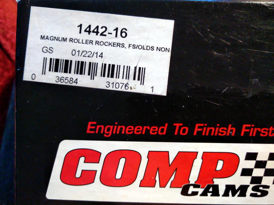 Why these roller tip rockers? Lots of reasons: way stronger than stock, less heat / friction, a fraction of the cost of a full roller assembly, and the lift ratio is very close the stock Corvair ratio, which itself is a matter of some debate. They do need to be modified. On the large central stud hole one side needs to be clearanced so that when mounted it will pivot far enough over to allow the roller tip to ride evenly over the valve stem. Also, the oil hole points directly down thereby filling up the chamber with oil. So the hole needs to be welded up and another oil hole drilled on the other side so oil shoots into the right place. Here is are the original oil holes welded up. 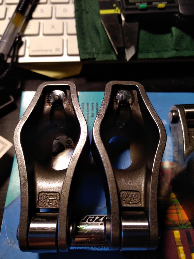 And new drilled oil holes on the other side. 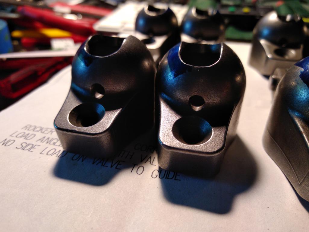 And all of them together. On the top row are the for the intake valves, the bottom row for exhaust. Be sure to order the matching pivot ball mounts if they don't come in the box. The balls mounts have four serrations to allow for more oil flow. 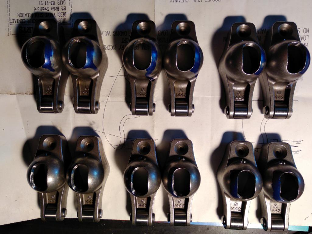 |
| r3dplanet |
 Jul 2 2018, 12:08 AM Jul 2 2018, 12:08 AM
Post
#188
|
|
Senior Member    Group: Members Posts: 679 Joined: 3-September 05 From: Portland, Oregon Member No.: 4,741 Region Association: None |
With the rocker arms sorted out it's finally time to doodle with the rocker geometry.
With non-stock cam, cylinders, base gaskets, and head gaskets it's reasonable to think that the stock pushrod length will be incorrect. So I ordered from Clark's an adjustable pushrod toolkit that comes with two adjustable pushrods and a pair of solid lifters. The idea is simple: when the valve opens and closes the valve stem tip needs to travel smoothly along the roller tip. Or the roller tip needs to travel smoothly across the valve stem tip. Not too high, not too low. So if the head and base gaskets are correct (I double checked mine and they are) then all that needs to be done is to lengthen or shorten the adjustable pushrod to make it kosher. First I do this visually. At rest the roller tip should be towards the bottom of the valve stem, and at full lift the roller tip should be towards the top of the valve stem. Here are exaggerated pics to show the difference. 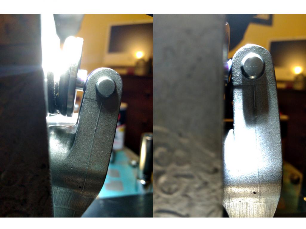 And here is a top view of the roller tip touching the valve stem. It really needs to roll along very flat on the valve stem. If the rocker wasn't clearanced to one side, it couldn't be made to ride flat. 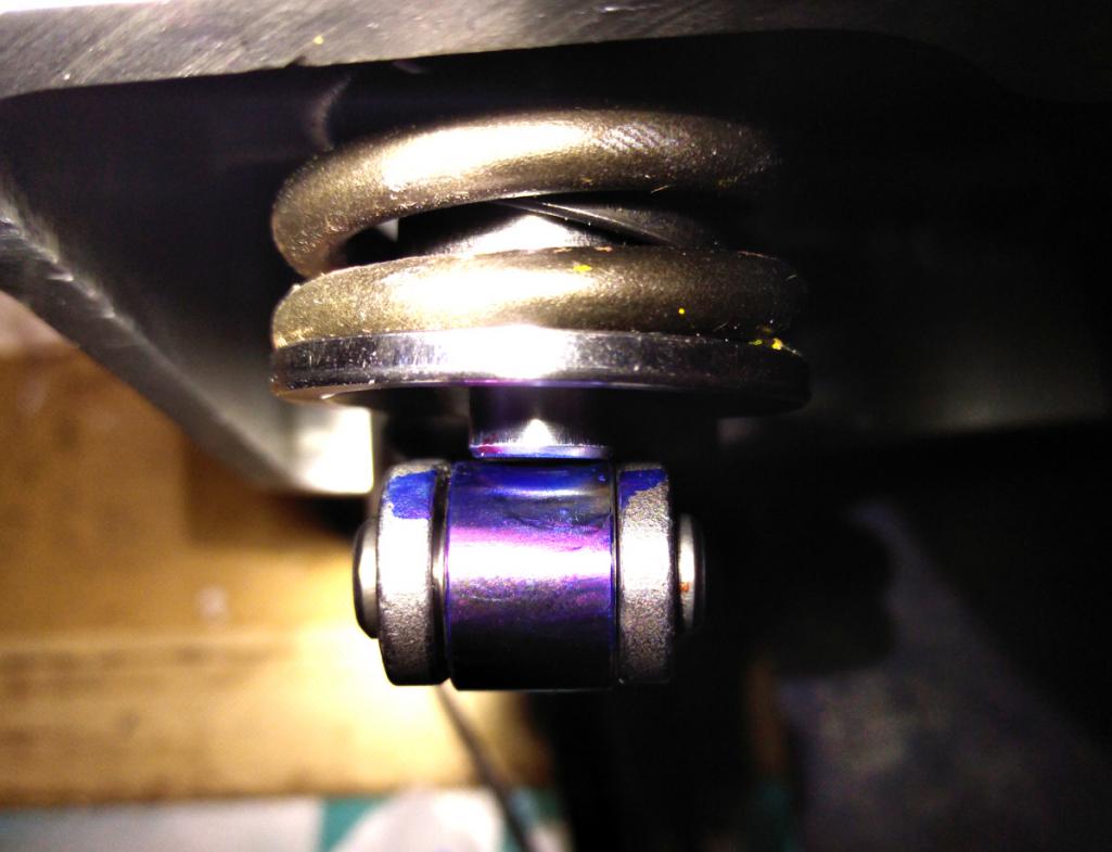 The instructions say to use a little piece of oiled paper and squish it onto the valve stem. This leaves a circular impression with the roller path clearly visible. It needs to be as close as centered as possible. I used blue Sharpie on the roller tip instead because it was easier to read. The tolerance is about 1/2 turn on the adjustable pushrod, or .025" by my measurement. A little note here about tolerance: pushrods are available in different sizes, so the choice is made to the nearest .025". Not the end of the world if off by a little bit. The pisser is that the solid lifter in the kit has a lower contact point with the pushrod than the hydraulic lifters. I'm using Melling JB-817 lifters. The difference in height of the contact point is 0.109" lower for the solid lifter. That means that in addition to getting the adjustable pushrod just right, this distance needs to be subtracted. Depending on the hydraulic lifter you use, this distance can be different. 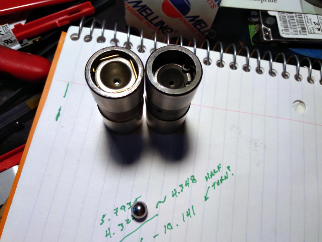 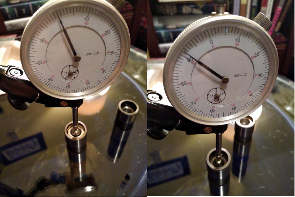 Then it's time for the arithmetic. This is where I get confused on what should be a simple task. The desired pushrod length is supposed to be the adjustable rod length + the lifter difference - the valve preload. Depending on the source, the pre-load is anywhere from 1/4 turn to 3/4 turn. So I'm using 1/2 turn, or .025". .... and doing so leaves me with a pushrod 0.20" SHORTER than stock. This blows my mind because every other write-up I've studied with VW big bore stuff shows a longer pushrod. Not shorter. I averaged my two best lengths and averaged them to get 10.040". I measure the stock rods at 10.240". The trouble here is that (a) I'm not sure this is correct and (b) I can't find shorter pushrods in this size. I might sacrifice one of my new hydraulic lifters by welding it solid and measuring again. Bummer. 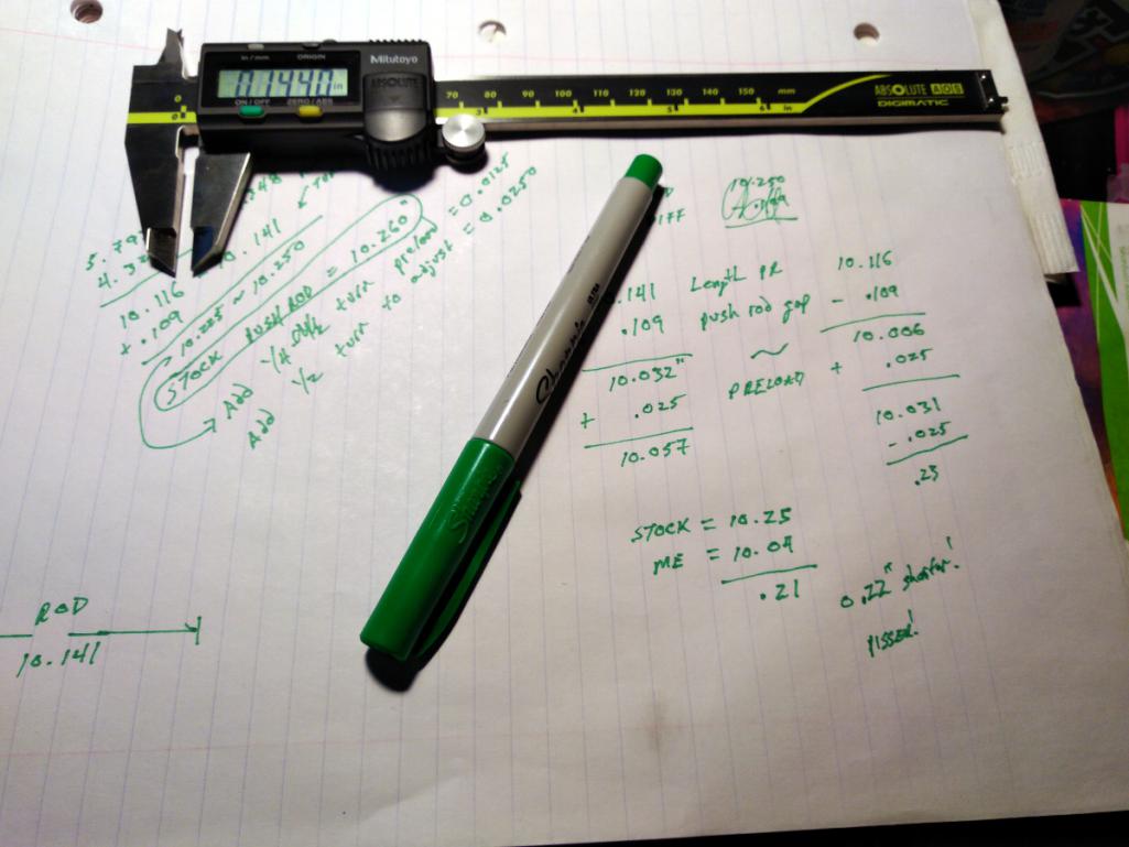 I'll sleep on it. |
| Tbrown4x4 |
 Jul 2 2018, 02:43 AM Jul 2 2018, 02:43 AM
Post
#189
|
|
Senior Member    Group: Members Posts: 706 Joined: 13-May 14 From: Port Orchard, WA Member No.: 17,338 Region Association: None 
|
Not sure I've ever seen a spec for the distance between the fan and the sheet metal. The critical measurement is the fan bearing flange to the top cover gasket surface. If that's right, the fan should be fine.
|
| worn |
 Jul 2 2018, 08:26 AM Jul 2 2018, 08:26 AM
Post
#190
|
|
can't remember     Group: Members Posts: 3,342 Joined: 3-June 11 From: Madison, WI Member No.: 13,152 Region Association: Upper MidWest 
|
|
| HalfMoon |
 Jul 2 2018, 09:12 AM Jul 2 2018, 09:12 AM
Post
#191
|
|
Senior Member    Group: Members Posts: 828 Joined: 13-November 12 From: Shenandoah Junction, WV Member No.: 15,144 Region Association: MidAtlantic Region |
A few years back I got all excited about doing a Corvair engine conversion for my 1971 car. The project waffled. Numbers were crunched and chewed. Thought and diagrams and opinions were drawn out over long winter evenings. One particularly rainy winter evening, I found an ad on Craigslist advertising a warehouse full of Corvair parts including engines. So my pal Rory and I drove a hundred miles into the boonies late one rainy night to what turned out to be an unmarked, geographically isolated, former slaughterhouse illuminated by a single 60 watt light bulb. No cell phone reception, no escape. We were met by a couple of toothless brothers who couldn't stop talking about Daddy. Seemingly they only did what Daddy wanted them to do. Daddy wanted them to sell the stash of Corvair parts. Daddy wanted them to steal my Toyota cargo van. Daddy needed to approve the transaction of cash for an engine. Daddy, it turned out, was long dead. The two brothers kept trying to separate Rory and I, and the creepier of the two brothers kept demanding my car keys so he could test drive my van, despite my insistence that it wasn't for sale. For the first time in a long time, I wish I had a tazer gun on me. The brothers eventually showed us exactly what I wanted - an RD code 1965 110HP engine. Fearing for our lives, Rory and I muscled the engine into the van while the brothers went to find more stuff for Daddy to sell to us, or you know, maybe a club or some rope or a ball gag or something. I left the $100 on the bench and tore the hell out. Rory and I laughed all the way back to town, ever so pleased that we were neither killed, nor raped, nor eaten. Plus, we were one up on a Corvair engine. So with a provenance like this, and seeing JRust's new car, Dr. Evil's project, and 914coops Nader's Nightmare all take shape I've finally decided to get serious about my own project: the VW-Porsche 914-C6. The "C" stands for Corvair. Odd off topic question. Can a set of Del 36's be used on a Corvair 140 engine? I looked around to see if anyone had done this and wasn't finding anything |
| r3dplanet |
 Jul 2 2018, 12:04 PM Jul 2 2018, 12:04 PM
Post
#192
|
|
Senior Member    Group: Members Posts: 679 Joined: 3-September 05 From: Portland, Oregon Member No.: 4,741 Region Association: None |
As far as all the write-ups I've seen indicate, there shouldn't be any special consideration for the hydraulic lifters. But having said that, I've decided to go ahead and weld up a hydraulic lifter and re-do the measurements just to see if I can get a more accurate reading. Great question. Food for thought.
QUOTE It's a hydraulic tappet isn't it? I never knew how those were measured, but thought that they pumped up when run. How does that figure in the calculations? I like the numbers and notes! |
| r3dplanet |
 Jul 2 2018, 12:13 PM Jul 2 2018, 12:13 PM
Post
#193
|
|
Senior Member    Group: Members Posts: 679 Joined: 3-September 05 From: Portland, Oregon Member No.: 4,741 Region Association: None |
Do you mean the dual throat DRLA carbs? If so, then yes you can. You need a pair of custom manifolds that adapt the carb to the head. There are custom units out there for triple bore carbs, but I'm using Weber 40 carbs. Tom Knoblauch makes them at americanflat6.com. I have a photo back at the top of Page 8, post 141.
Basically you can make any manifold you want if you can TiG weld and have a mill. I don't have those but I know who does. For me it was an easy choice because I'm very familiar with Weber / Dellorto carbs. QUOTE Odd off topic question. Can a set of Del 36's be used on a Corvair 140 engine? I looked around to see if anyone had done this and wasn't finding anything |
| Dr Evil |
 Jul 2 2018, 07:45 PM Jul 2 2018, 07:45 PM
Post
#194
|
|
Send me your transmission!                Group: Members Posts: 23,032 Joined: 21-November 03 From: Loveland, OH 45140 Member No.: 1,372 Region Association: MidAtlantic Region 
|
As far as all the write-ups I've seen indicate, there shouldn't be any special consideration for the hydraulic lifters. But having said that, I've decided to go ahead and weld up a hydraulic lifter and re-do the measurements just to see if I can get a more accurate reading. Great question. Food for thought. QUOTE It's a hydraulic tappet isn't it? I never knew how those were measured, but thought that they pumped up when run. How does that figure in the calculations? I like the numbers and notes! The stock lifters are set to 0 and then tightened a specific amount....then you run the engine and adjust until quiet. No shit. Videos out there and special valve covers are sold or made. Its a mess to do, Ive done it. As for roller rockers, go with a known source. I "saved money" from a guy that ended up not only selling cheap chinese crap, he sold the ones for a chevy V8 which have a different angle of attack. He promised they were correctly angled for corvair, I asked specifically. Well, check out my bus thread towards the end to see the destruction. The first one ate through the rocker stud and the others were not far behind. |
| r3dplanet |
 Jul 2 2018, 10:25 PM Jul 2 2018, 10:25 PM
Post
#195
|
|
Senior Member    Group: Members Posts: 679 Joined: 3-September 05 From: Portland, Oregon Member No.: 4,741 Region Association: None |
An expensive cautionary tale. It still makes me angry. More so because that guy is still selling them.
The valve adjust videos are very cool. You slice a crappy valve cover down the long axis so it captures the oil (sort of) and then you tighten the rocker nut to quiet the valve. According to the book Performance Corvairs the best way to do this is as follows: 1. Set rocker distance to just touching (zero lash as Dr. Evil said). 2. Run the engine, and then on each rocker nut tighten until it quiets, or about 1/2 turn - which I found out yesterday with valve geometry is about .020". 3. Turn off the engine after all are completed and let it cool. 4. Give each valve another 1/8 turn. I have some tooling being made up will get back to the geometry soon... As far as all the write-ups I've seen indicate, there shouldn't be any special consideration for the hydraulic lifters. But having said that, I've decided to go ahead and weld up a hydraulic lifter and re-do the measurements just to see if I can get a more accurate reading. Great question. Food for thought. QUOTE It's a hydraulic tappet isn't it? I never knew how those were measured, but thought that they pumped up when run. How does that figure in the calculations? I like the numbers and notes! The stock lifters are set to 0 and then tightened a specific amount....then you run the engine and adjust until quiet. No shit. Videos out there and special valve covers are sold or made. Its a mess to do, Ive done it. As for roller rockers, go with a known source. I "saved money" from a guy that ended up not only selling cheap chinese crap, he sold the ones for a chevy V8 which have a different angle of attack. He promised they were correctly angled for corvair, I asked specifically. Well, check out my bus thread towards the end to see the destruction. The first one ate through the rocker stud and the others were not far behind. |
| r3dplanet |
 Jul 2 2018, 10:54 PM Jul 2 2018, 10:54 PM
Post
#196
|
|
Senior Member    Group: Members Posts: 679 Joined: 3-September 05 From: Portland, Oregon Member No.: 4,741 Region Association: None |
... but first let's make a sandwich.
The process is easy for once. Clean the top of the engine case with acetone. Coat the first of two identical engine cover gaskets. <shameless product placement> I use Permatex High Tack in the spray bottle. It's my favorite gasket sealer because it's clean to use and has a long working time so I can relax and have fun. I wish Gasgacinch had a spray version also. But these two are very similar, even the same color and smell. 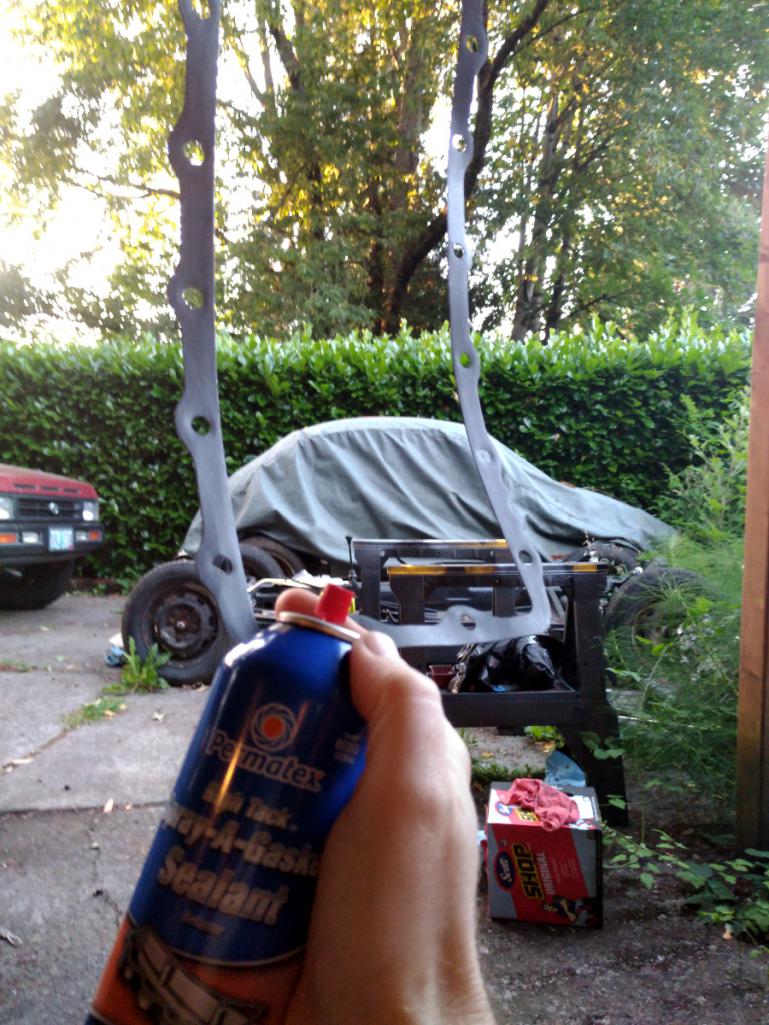 </shameless product placement> Then add the baffle plate, the other coated gasket, and then the top cover. Like so: 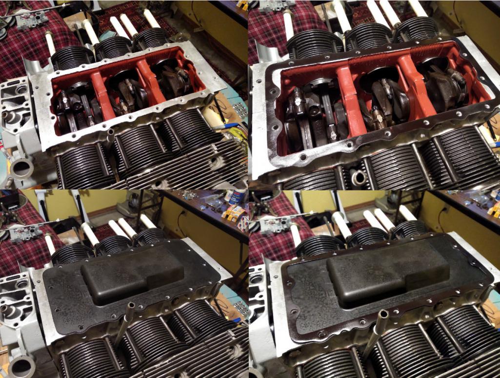 Finally just torque down all sixteen to 150 inch pounds after kissing each new bolt with a bit of JetLube. I went in three stages of 50 in/lbs until 150. I'm using stainless 5/16-18 x 1" bolts with lockwashers and washers. I don't want to besmirch the aluminum case. 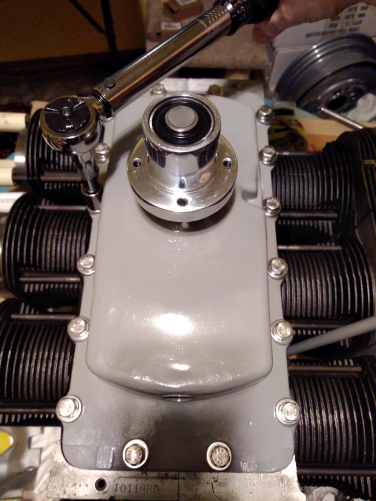 Here's the Dagwood all assembled. It feels a bit sad to not see the pistons any more. Not that I want to have a major problem and have to get back into it that far. Perish the thought. 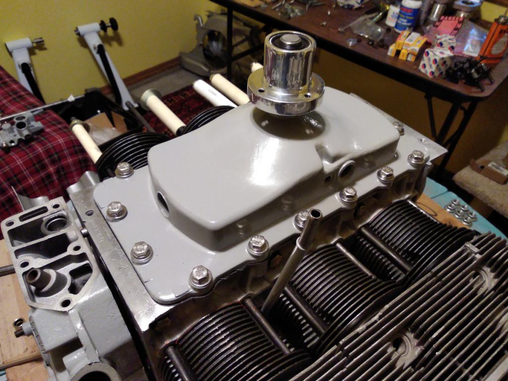 |
| Porschef |
 Jul 3 2018, 04:24 AM Jul 3 2018, 04:24 AM
Post
#197
|
|
How you doin'     Group: Members Posts: 2,180 Joined: 7-September 10 From: LawnGuyland Member No.: 12,152 Region Association: North East States 
|
Awesome. Love the orange fan and pretty much everything else
(IMG:style_emoticons/default/beerchug.gif) (IMG:style_emoticons/default/beerchug.gif) (IMG:style_emoticons/default/pray.gif) |
| Dr Evil |
 Jul 3 2018, 06:41 AM Jul 3 2018, 06:41 AM
Post
#198
|
|
Send me your transmission!                Group: Members Posts: 23,032 Joined: 21-November 03 From: Loveland, OH 45140 Member No.: 1,372 Region Association: MidAtlantic Region 
|
... but first let's make a sandwich. The process is easy for once. Clean the top of the engine case with acetone. Coat the first of two identical engine cover gaskets. <shameless product placement> I use Permatex High Tack in the spray bottle. It's my favorite gasket sealer because it's clean to use and has a long working time so I can relax and have fun. I wish Gasgacinch had a spray version also. But these two are very similar, even the same color and smell.  </shameless product placement> Then add the baffle plate, the other coated gasket, and then the top cover. Like so:  Finally just torque down all sixteen to 150 inch pounds after kissing each new bolt with a bit of JetLube. I went in three stages of 50 in/lbs until 150. I'm using stainless 5/16-18 x 1" bolts with lockwashers and washers. I don't want to besmirch the aluminum case.  Here's the Dagwood all assembled. It feels a bit sad to not see the pistons any more. Not that I want to have a major problem and have to get back into it that far. Perish the thought.  I uses Great Stuff, which is more gooey. Ill have to try your stuff. |
| r3dplanet |
 Jul 8 2018, 08:41 PM Jul 8 2018, 08:41 PM
Post
#199
|
|
Senior Member    Group: Members Posts: 679 Joined: 3-September 05 From: Portland, Oregon Member No.: 4,741 Region Association: None |
I like Permatex "Right Stuff" if I'm going metal to metal for sure. I've never tried is as a gasket sealant. Maybe I should.. (IMG:style_emoticons/default/idea.gif)
QUOTE I uses Great Stuff, which is more gooey. Ill have to try your stuff. |
| r3dplanet |
 Jul 8 2018, 08:59 PM Jul 8 2018, 08:59 PM
Post
#200
|
|
Senior Member    Group: Members Posts: 679 Joined: 3-September 05 From: Portland, Oregon Member No.: 4,741 Region Association: None |
Okay. I'm doing little bits of this and this and that while I sort out two remaining issues - the oil pan and modified lifters for rocker geometry. Those will take a few days at least so it's time to work on pesky bits.
My attention has mostly been the Cover of Many Uses. It took quite a while to sand down the mating surfaces and lap them completely flat. I'm using my ever-handy flat glass plate and sandpaper. While in there, the 90 degree oil cooler connector is getting the same treatment. Just to review, the Cover of Many Uses is a two-part assembly which houses the distributor, oil pressure sender, oil filler, mechanical fuel pump, and two oil bypass valves, one oil pressure regulator, and the oil pump spur gears. But it's getting a bit of a reprieve because I'm using an electric fuel pump instead of the mechanical one. Better all around. The oil pump threw me for a bit of a loop. Here's the order of installation: 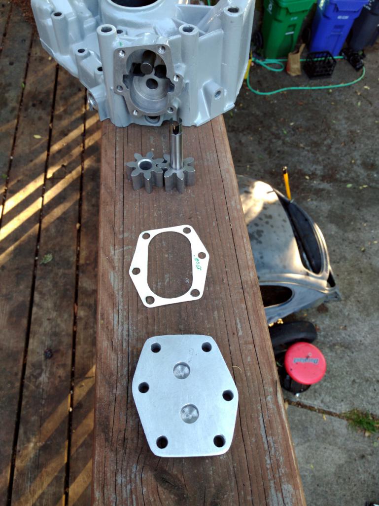 The clearance between the spur gears to the bottom plate is suppose to be .002-.003". Fair enough. The new oil pump comes with different size gaskets but none of them measured to nominal thickness. So a .010" gasket is really .0075". Great. I don't like Plasti-Gauge but this seems like an okay place for it. But no variant of gasket would get the correct clearance. Except for one, but when I twisted the drive gear with a screw driver to simulate the distributor gear, it rubbed against the bottom plate. 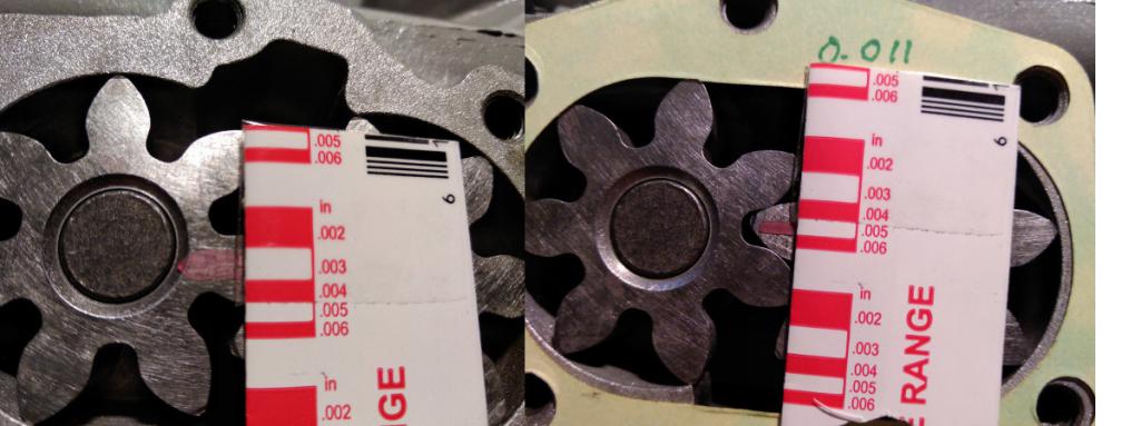 Further irritation came from the fact that use of feeler thickness gauges didn't match the Plasti-Gauge readings. Finally I realized that my NAPA-branded feelers were the wrong size! According to my micrometer, the .002 feeler is .007, and the .003 is .009. Lovely. I have a nice Mitutoyo set on order. The last bit of despair came when I measured the original oil pump gears with the new ones. As you can see, the new ones are .798-ish, but the old one is dead nuts on .800". The service manual says GM will happily provide oil gears in increasing thicknesses of .001" to get the correct fit, but those are long gone. I called the parts vendor and the guy measured some on the shelf and said, "yeah, they're all like that." 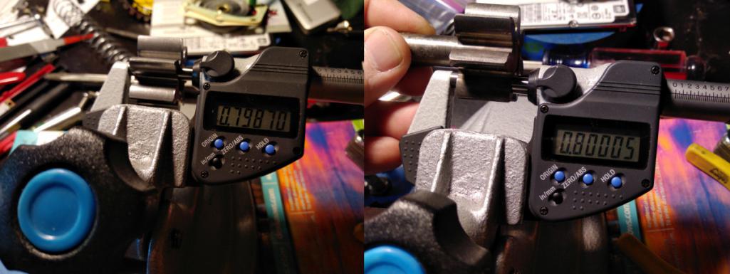 Right. So I have another oil pump coming from Melling, and maybe it will be the right size. Normally I wouldn't squawk but oil pump clearances are critical. |
  |
1 User(s) are reading this topic (1 Guests and 0 Anonymous Users)
0 Members:

|
Lo-Fi Version | Time is now: 23rd November 2024 - 05:51 PM |
Invision Power Board
v9.1.4 © 2024 IPS, Inc.


