|
|

|
Porsche, and the Porsche crest are registered trademarks of Dr. Ing. h.c. F. Porsche AG.
This site is not affiliated with Porsche in any way. Its only purpose is to provide an online forum for car enthusiasts. All other trademarks are property of their respective owners. |
|
|
  |
| 76-914 |
 Jun 12 2017, 09:51 PM Jun 12 2017, 09:51 PM
Post
#741
|
|
Repeat Offender & Resident Subaru Antagonist           Group: Members Posts: 13,634 Joined: 23-January 09 From: Temecula, CA Member No.: 9,964 Region Association: Southern California 
|
That doesn't look like it's enough. Would be worth it to crunch numbers. The OUT needs to be 20% larger than the IN to account for heat expansion of the air. An insulator between the hose and the tank might help. I don't think the heat transfer would be THAT much but it's possible. I thought it was 50% larger? I think you probably could use with a larger outlet for your radiator, but JUST ducting it will certainly increase your efficiency by a wide margin methinks. Could be a fun foam or cardboard adventure depending on how you shroud it (IMG:style_emoticons/default/smile.gif) See that pink string, Andrew? That is the forward/top corner of the proposed duct. Doesn't give me a Hell of a lot of room to tie in the shroud but doable. I laid out some measurements in case I need to duct. I've a couple of cool ducting ideas, I mentioned canvas earlier, that I will bounce off you guys if it comes to that. This is going to get handled and put to bet this summer. (IMG:style_emoticons/default/beerchug.gif) |
| Chris914n6 |
 Jun 12 2017, 10:18 PM Jun 12 2017, 10:18 PM
Post
#742
|
|
Jackstands are my life.     Group: Members Posts: 3,413 Joined: 14-March 03 From: Las Vegas, NV Member No.: 431 Region Association: Southwest Region |
I thought it was 50% larger? Just 20%. A bunch of engineering went into my AC unit, some was actual heater core and radiator temps and air volume. I'd always heard that it's twice the outlet size per inlet size... (IMG:style_emoticons/default/idea.gif) That guy was blowing smoke up your ass. The formula for thermal expansion is on the internet if you want to do the calculations. I think any further discussions of this should be in a separate thread. The hot air would have to be blowing past the trunk seal to heat the gas tank as the tank doesn't actually touch the metal divider. Opening up the truck holes to 2x inlet air should alleviate that if it's the problem. |
| Chris H. |
 Jun 12 2017, 10:43 PM Jun 12 2017, 10:43 PM
Post
#743
|
|
Senior Member     Group: Members Posts: 4,048 Joined: 2-January 03 From: Chicago 'burbs Member No.: 73 Region Association: Upper MidWest 
|
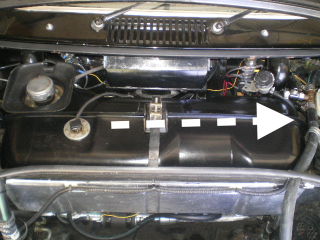
This is what concerns me if the tank is getting hot. The hoses are very close to it on both sides. Can't hurt to wrap those with some insulated wrap or sleeves.
 |
| 76-914 |
 Jun 13 2017, 09:18 AM Jun 13 2017, 09:18 AM
Post
#744
|
|
Repeat Offender & Resident Subaru Antagonist           Group: Members Posts: 13,634 Joined: 23-January 09 From: Temecula, CA Member No.: 9,964 Region Association: Southern California 
|
I thought it was 50% larger? Just 20%. A bunch of engineering went into my AC unit, some was actual heater core and radiator temps and air volume. I'd always heard that it's twice the outlet size per inlet size... (IMG:style_emoticons/default/idea.gif) That guy was blowing smoke up your ass. The formula for thermal expansion is on the internet if you want to do the calculations. I think any further discussions of this should be in a separate thread. The hot air would have to be blowing past the trunk seal to heat the gas tank as the tank doesn't actually touch the metal divider. Opening up the truck holes to 2x inlet air should alleviate that if it's the problem. Chris, feel free to download any info you feel pertinent to this problem. It it saves someone headaches, time and $$$, do it. (IMG:style_emoticons/default/agree.gif) w/ the 20% rule as this is what I've read, as well. The hot air is blowing past the seal. Or what's left of it. I did trim it to allow the hoses to pass over the firewall. Even the unmolested seals let air pass by the ends of the seal. The hot air is then drawn down along the sides of the tank on its way out the steering column cover. My cover has half of a small butane tank welded in to cover my first attempt at a clutch master cylinder. I believe this exacerbates the problem. Kinda like blowing across the top of a Coke bottle causing a bit of negative pressure. Anyone have an extra cover for sale?? (IMG:style_emoticons/default/beerchug.gif) This is what concerns me if the tank is getting hot. The hoses are very close to it on both sides. Can't hurt to wrap those with some insulated wrap or sleeves. I've touched both the hoses as well as the fuel pump when it quits and they aren't that hot. (IMG:style_emoticons/default/confused24.gif) You might be right, though. Changing those out and ducting is next on the list if this doesn't do the trick. (IMG:style_emoticons/default/beerchug.gif)  |
| 914forme |
 Jun 13 2017, 10:29 PM Jun 13 2017, 10:29 PM
Post
#745
|
|
Times a wastin', get wrenchin'!     Group: Members Posts: 3,896 Joined: 24-July 04 From: Dayton, Ohio Member No.: 2,388 Region Association: None 
|
I thought it was 50% larger? Just 20%. A bunch of engineering went into my AC unit, some was actual heater core and radiator temps and air volume. I'd always heard that it's twice the outlet size per inlet size... (IMG:style_emoticons/default/idea.gif) That guy was blowing smoke up your ass. The formula for thermal expansion is on the internet if you want to do the calculations. I think any further discussions of this should be in a separate thread. The hot air would have to be blowing past the trunk seal to heat the gas tank as the tank doesn't actually touch the metal divider. Opening up the truck holes to 2x inlet air should alleviate that if it's the problem. (IMG:style_emoticons/default/confused24.gif) if Kent only needs 20% that is an extra 36 sq inches based off his quoted inlet size of 180 sq inches. So why are you suggesting he adds an additional 180 sq inches to his current 180 squar inches to create 360 squar inches of outlet. Which so happens to be a 100% increase. Or 2x the opening size from the ratio of inlet to outlet. And you said the person who recommended that was blowing smoke up Kent's ass. Then you went and blew the same smoke up his ass (IMG:style_emoticons/default/confused24.gif) It might have been a different color but it all smells the same (IMG:style_emoticons/default/stromberg.gif) Kent your issue is not enough exit. Ducting will help as what you are doing right now is like trying to corral free range cats. It just can't be done. Much easier to domesticate the poor bastards then push them down a narrow shoot. So go out and add duct work, or add bigger holes. Or remove them little fans you got there, and add some duct work and a small snowmobile engine. Use it to drive a turbine fan, and make your car into a sucker car. Then you have no problem getting them pesky cats rounded up. And everything else in your path will be sucked up and spit out in a million little pieces. Of course you could then take this turbines outlet air, and duct it into your intake, and well then you have your self a supper charger (IMG:style_emoticons/default/shades.gif) Now you have created a whole mther set of problems to figure out, but you solved your cooling issue, in a very golbergian fashion. (IMG:style_emoticons/default/av-943.gif) |
| 76-914 |
 Jun 14 2017, 08:11 AM Jun 14 2017, 08:11 AM
Post
#746
|
|
Repeat Offender & Resident Subaru Antagonist           Group: Members Posts: 13,634 Joined: 23-January 09 From: Temecula, CA Member No.: 9,964 Region Association: Southern California 
|
I'm thinking your right Stephen but hoping your wrong. I'm prepared to duct it but thought I'd try opening up the wheel wells a bit first. BTW, I think Chris was saying that 20% is the rule but if I was going to increase the opening by a factor of 2 I'd be just fine. How's your project coming along? Kent (IMG:style_emoticons/default/beerchug.gif)
|
| mgp4591 |
 Jun 14 2017, 10:18 AM Jun 14 2017, 10:18 AM
Post
#747
|
|
914 Guru      Group: Members Posts: 5,481 Joined: 1-August 12 From: Salt Lake City Ut Member No.: 14,748 Region Association: Intermountain Region 
|
I'm thinking your right Stephen but hoping your wrong. I'm prepared to duct it but thought I'd try opening up the wheel wells a bit first. BTW, I think Chris was saying that 20% is the rule but if I was going to increase the opening by a factor of 2 I'd be just fine. How's your project coming along? Kent (IMG:style_emoticons/default/beerchug.gif) I think 20% additional is only 36 sq. inches... and I really wouldn't want Chris to blow smoke up my ass... (IMG:style_emoticons/default/blink.gif) if I want it, I'll pay someone else to do it in Vegas... (IMG:style_emoticons/default/happy11.gif) |
| 76-914 |
 Jun 26 2017, 02:07 PM Jun 26 2017, 02:07 PM
Post
#748
|
|
Repeat Offender & Resident Subaru Antagonist           Group: Members Posts: 13,634 Joined: 23-January 09 From: Temecula, CA Member No.: 9,964 Region Association: Southern California 
|
I've put this off for long enough. I tried driving "the proverbial" square plug in a round hole long enough. I should have done this long ago but chose to eliminate the other possibilities first. My mistake. (IMG:style_emoticons/default/mad.gif)
Before I go on I want to pass on a condensed version of my thinking and failures leading up to this. If you didn't already know, my gas tank has been getting hot and manifesting itself into at least two other problems. There may be others that haven't reared their ugly heads yet. When the tank reached "X" temp i.e. hot to the touch I could feel the metal dash and it would be hot. This in turn made it damned uncomfortable to ride in any ambient temp greater than 40F. Within minutes of feeling the hot air emanate from the dash the fuel pressure would drop from 42psi to less than 10psi at which point it would stall. After letting the tank cool down I would repeat the process. (IMG:style_emoticons/default/headbang.gif) What confused me was that I had nearly 5000 miles on the Odo before this problem surfaced. (IMG:style_emoticons/default/idea.gif) Hmmm. What could have happened that might have caused this? I remembered changing the fuel pump after it conked out and immediately surmised that the new pump was heating the tank. Why didn't the old one do this? I don't know and failed to ask myself this all important question. (IMG:style_emoticons/default/screwy.gif) My solution; change out the heavily modified 914 gas tank and replace it with a stock tank and larger Walbro pump to meet the 3 liter'e appetite. I completed that change about 1 week before WCR2017. I've learned not to put much faith into my diagnostic abilities so I towed the 914 to WCR. Good call because my efforts were in vein. Just ask Wes. We sat in the heat on the side of the road for 2 hours whilst it cooled. Thank God I wasn't carrying that day or I'd have taken that SOB out back and shot it.(IMG:style_emoticons/default/ar15.gif) Back on track. What changed that caused my gas tank to heat? (IMG:style_emoticons/default/idea.gif) Then I remembered and as posted here earlier, I had changed from a single core Scirocco radiator to the favored Celica dual core racing type when this "heated gas tank" conundrum began. Btw, that is a Hell of a good radiator. In error I believed the newer radiator was more free flowing and allowed more heat to saturate the tank but that thinking was flawed. The same amount of heated water at "X" temp was passing thru the new radiator as the old. I now believe (or should I say, "This time I think it is.....) it was a simple matter of inlet area > outlet area. When I drilled out the front wheel wells I made the exhaust area 40% larger than the opening for the radiator. Right before I changed out the radiator I increased the inlet opening hoping for some relief from over heating. For some reason this evaded the limits of my memory until this weekend. (IMG:style_emoticons/default/headbang.gif) No loss. I'm ducting this thing and putting it to bed once and for all. In order to duct the radiator I will have to make a couple of PITA changes. The first change I've been anticipating. Change out the radiator lines that presently run thru the longs in favor of the bit larger 1 3/8" hose fitted beneath the car. The second will be rerouting or replacement of the AC lines in the frunk. These 2 things will clean up the frunk allowing the duct. I had bounced around a few ideas on materials and ultimately settled on Aluminum for all the usual reasons. I still had a few sheets of 2024 laying around so I decided to start throwing some metal at it. I have some E Glass on hand but I believe it will ultimately be faster to Fab it than Dab it. This is where I'm presently at. My target outlet area is 180" sq.;90" sq per side. This is a pic of my template. 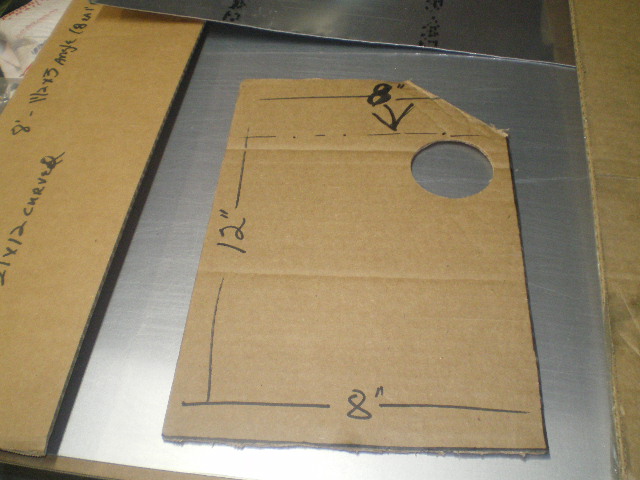 Left side roughly outlined with some tape. The wire looms are very close to the lower left corner but should work. 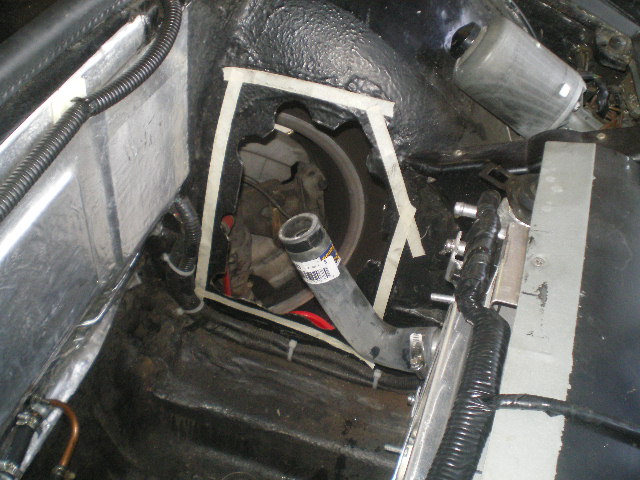 Right side. Same thing except I've got the AC hoses to deal with here. Notice the AC bulkhead fittings at the lower right corner? outlet frame is beginning to take form here as well. 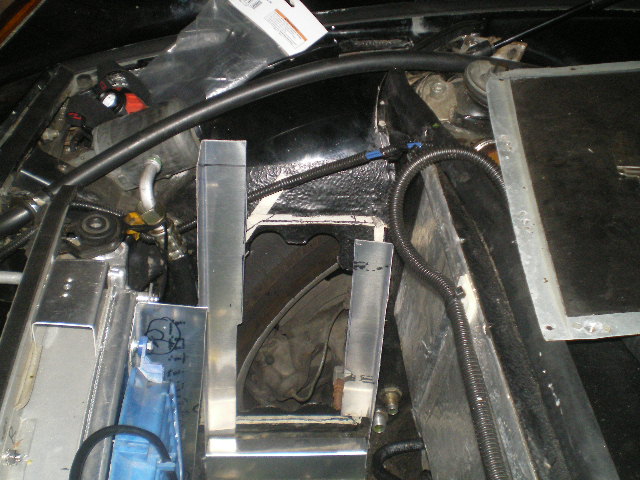 And a few more with the side attach pieces mounted to the radiator outlets. This design will have two plenums. One for each side. More pic's to come once things cool down here. 105F yesterday; 103F today! (IMG:style_emoticons/default/happy11.gif) 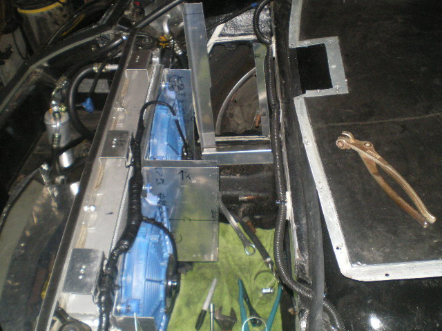 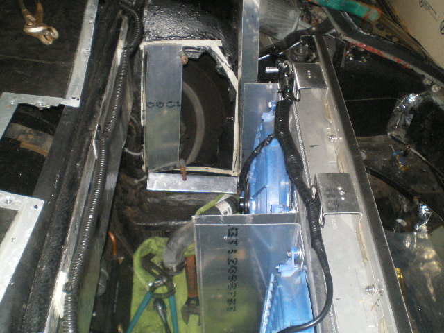 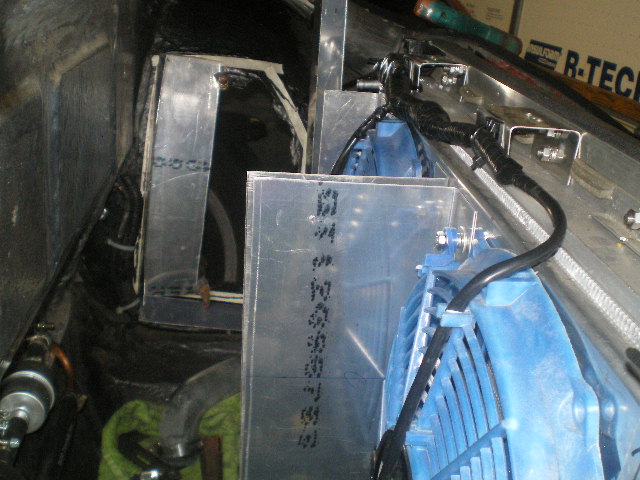 Attached image(s) 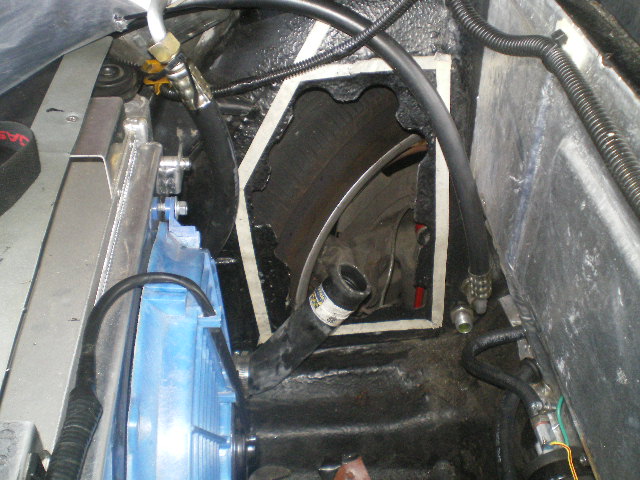
|
| 914forme |
 Jun 26 2017, 06:31 PM Jun 26 2017, 06:31 PM
Post
#749
|
|
Times a wastin', get wrenchin'!     Group: Members Posts: 3,896 Joined: 24-July 04 From: Dayton, Ohio Member No.: 2,388 Region Association: None 
|
Why divide the center? Just wondering are your fans staged? I think your making this a bit to complicated.
But then that is the pot calling the kettle black. (IMG:style_emoticons/default/av-943.gif) |
| 76-914 |
 Jun 29 2017, 08:46 AM Jun 29 2017, 08:46 AM
Post
#750
|
|
Repeat Offender & Resident Subaru Antagonist           Group: Members Posts: 13,634 Joined: 23-January 09 From: Temecula, CA Member No.: 9,964 Region Association: Southern California 
|
Baby steps. It happens every time I design and build simultaneously. (IMG:style_emoticons/default/headbang.gif)
Paper template for bottom tray piece being fitted: 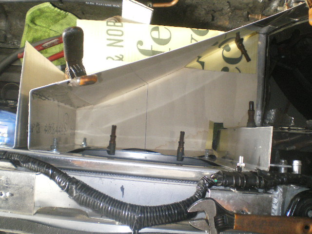 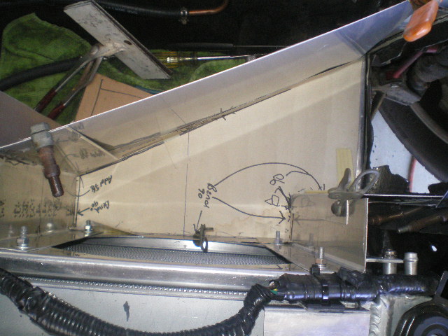 The bottom piece now cut, positioned and clecoed in place. 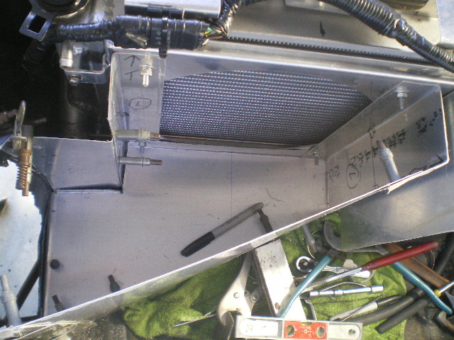 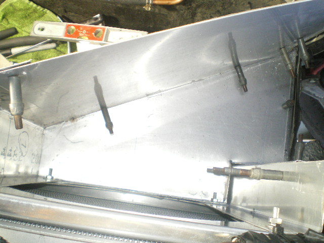 The piece in front of the radiator hose connection is an access cover and will be held in place with SS screws rather than rivets. The top piece which will be removable for service and access is next. It will surely by a Royal PITA as there are multiple angles that need to meet. (IMG:style_emoticons/default/sad.gif) 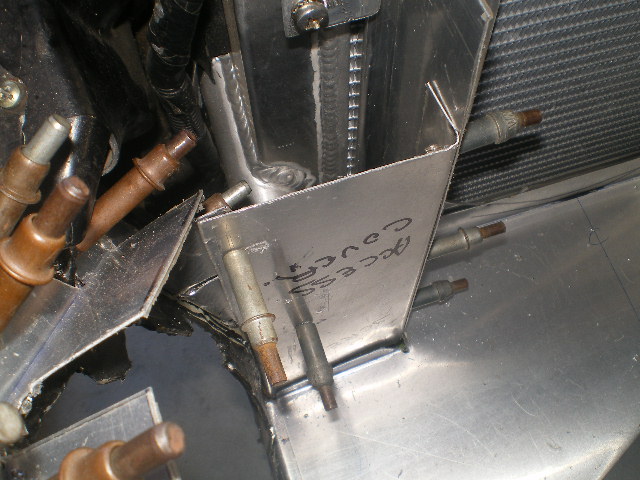 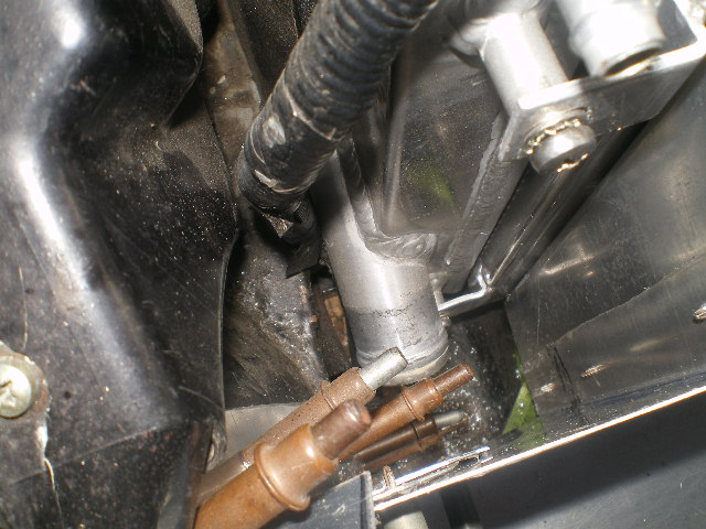 |
| 914forme |
 Jun 29 2017, 09:01 AM Jun 29 2017, 09:01 AM
Post
#751
|
|
Times a wastin', get wrenchin'!     Group: Members Posts: 3,896 Joined: 24-July 04 From: Dayton, Ohio Member No.: 2,388 Region Association: None 
|
That made it more clear keep up the work
|
| A&P Mech |
 Jun 29 2017, 03:18 PM Jun 29 2017, 03:18 PM
Post
#752
|
|
Member   Group: Members Posts: 401 Joined: 10-September 13 From: United States Member No.: 16,371 Region Association: Rocky Mountains |
(IMG:style_emoticons/default/popcorn[1].gif) This is pretty cool. I purchased the aluminum to do something like this a while ago. Looks like I will be riding your coat tails yet again. Thanks for doing the heavy lifting Kent! (IMG:style_emoticons/default/popcorn[1].gif)
|
| Andyrew |
 Jun 29 2017, 04:08 PM Jun 29 2017, 04:08 PM
Post
#753
|
|
Spooling.... Please wait           Group: Members Posts: 13,377 Joined: 20-January 03 From: Riverbank, Ca Member No.: 172 Region Association: Northern California 
|
I like it! I think the divide is important so the flow goes the right way and doesnt disrupt. I think this will help a lot!!!
Personally I would have used expanding foam to make a template, shape it to fix and fiberglass it. But your way works (IMG:style_emoticons/default/smile.gif) |
| 76-914 |
 Jun 29 2017, 05:48 PM Jun 29 2017, 05:48 PM
Post
#754
|
|
Repeat Offender & Resident Subaru Antagonist           Group: Members Posts: 13,634 Joined: 23-January 09 From: Temecula, CA Member No.: 9,964 Region Association: Southern California 
|
I like it! I think the divide is important so the flow goes the right way and doesnt disrupt. I think this will help a lot!!! Personally I would have used expanding foam to make a template, shape it to fix and fiberglass it. But your way works (IMG:style_emoticons/default/smile.gif) I was leaning towards glassing it Andrew. I even have a partial roll of some S glass. IIRC, it is good to 200C. What I couldn't wrap my head around was how I would apply resin to the bottom. (IMG:style_emoticons/default/confused24.gif) On a high note, it passed the remove part of removable today. The test will be the install part of re-installation. I hated that it needed to be designed this way but as sure as God made little Green Apples had I not done it ...........well you know. |
| 76-914 |
 Jun 29 2017, 05:53 PM Jun 29 2017, 05:53 PM
Post
#755
|
|
Repeat Offender & Resident Subaru Antagonist           Group: Members Posts: 13,634 Joined: 23-January 09 From: Temecula, CA Member No.: 9,964 Region Association: Southern California 
|
(IMG:style_emoticons/default/popcorn[1].gif) This is pretty cool. I purchased the aluminum to do something like this a while ago. Looks like I will be riding your coat tails yet again. Thanks for doing the heavy lifting Kent! (IMG:style_emoticons/default/popcorn[1].gif) Well at least wait a few months. You know how many mistakes I've made during this build. Some of them take months to rear their ugly heads! (IMG:style_emoticons/default/lol-2.gif) |
| mgp4591 |
 Jun 30 2017, 03:52 AM Jun 30 2017, 03:52 AM
Post
#756
|
|
914 Guru      Group: Members Posts: 5,481 Joined: 1-August 12 From: Salt Lake City Ut Member No.: 14,748 Region Association: Intermountain Region 
|
I hated that it needed to be designed this way but as sure as God made little Green Apples had I not done it ...........well you know.
[/quote] What? That it wouldn't have rained in Indianapolis in the summertime?? (IMG:style_emoticons/default/shades.gif) |
| Andyrew |
 Jun 30 2017, 08:19 AM Jun 30 2017, 08:19 AM
Post
#757
|
|
Spooling.... Please wait           Group: Members Posts: 13,377 Joined: 20-January 03 From: Riverbank, Ca Member No.: 172 Region Association: Northern California 
|
I like it! I think the divide is important so the flow goes the right way and doesnt disrupt. I think this will help a lot!!! Personally I would have used expanding foam to make a template, shape it to fix and fiberglass it. But your way works (IMG:style_emoticons/default/smile.gif) I was leaning towards glassing it Andrew. I even have a partial roll of some S glass. IIRC, it is good to 200C. What I couldn't wrap my head around was how I would apply resin to the bottom. (IMG:style_emoticons/default/confused24.gif) On a high note, it passed the remove part of removable today. The test will be the install part of re-installation. I hated that it needed to be designed this way but as sure as God made little Green Apples had I not done it ...........well you know. You remove the foam mold, glass it, after wrapping it in foil, then break the foam out after the glass has set. Also technically speaking you dont need to do a bottom. Just the portion that forces air to the fender and run it to the floor. |
| Andyrew |
 Jun 30 2017, 08:23 AM Jun 30 2017, 08:23 AM
Post
#758
|
|
Spooling.... Please wait           Group: Members Posts: 13,377 Joined: 20-January 03 From: Riverbank, Ca Member No.: 172 Region Association: Northern California 
|
Also you can make the base foundation from chickenwire or some other extremely maluable substrate. I might do that on mine, either foam the wire and smooth or lay the first layer with cloth.
|
| 76-914 |
 Jul 1 2017, 07:11 PM Jul 1 2017, 07:11 PM
Post
#759
|
|
Repeat Offender & Resident Subaru Antagonist           Group: Members Posts: 13,634 Joined: 23-January 09 From: Temecula, CA Member No.: 9,964 Region Association: Southern California 
|
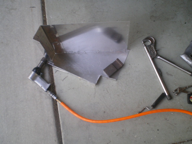
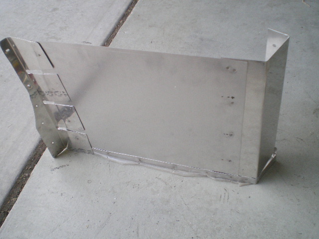
More baby steps and it's slowly coming together. This is the biggest part I could put together and still be able to remove it. The remainder will be pop riveted or screwed together.
  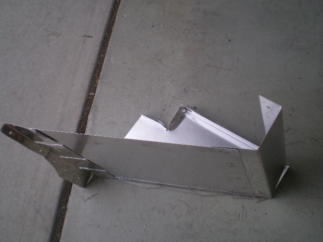 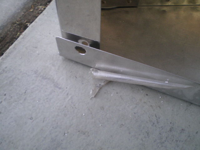 This is the piece I made to square up that weird angle on the flange at the wheel well. Also a few shots of it's template. 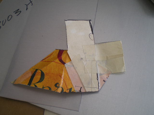 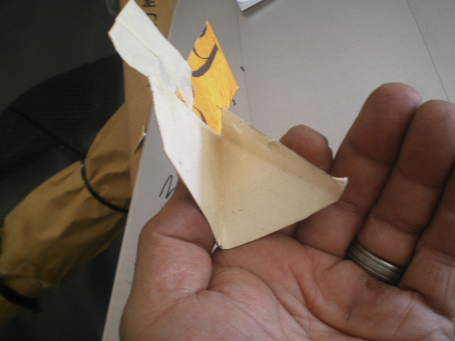 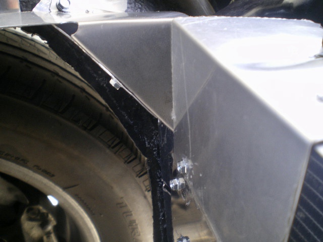 With the small gusset in place the top piece can be a flat sheet. (IMG:style_emoticons/default/piratenanner.gif) 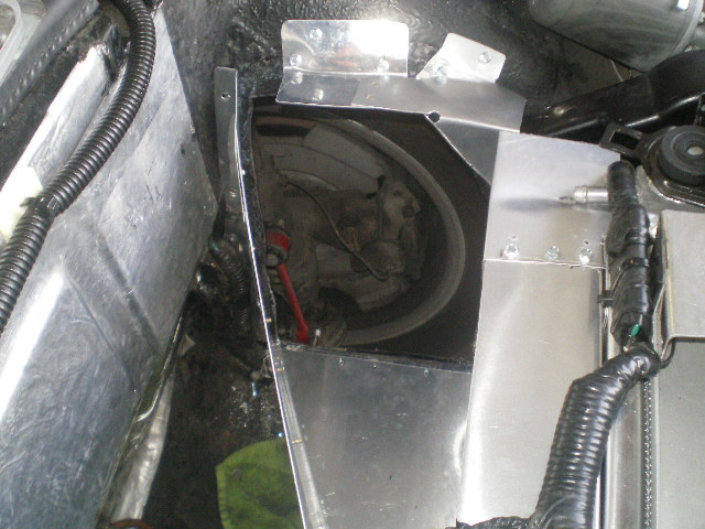 Because of the off center outlet on the Celica radiator I had some side stepping to do. I used 2 Goodyear #60083 1.25" extended 90's and shortened one to make it a plain 90, attached the two and dodged a bullet. 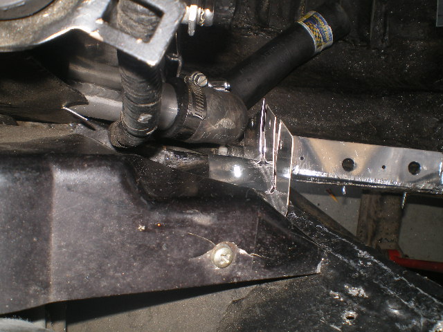 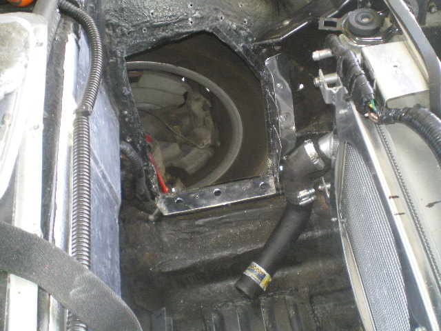 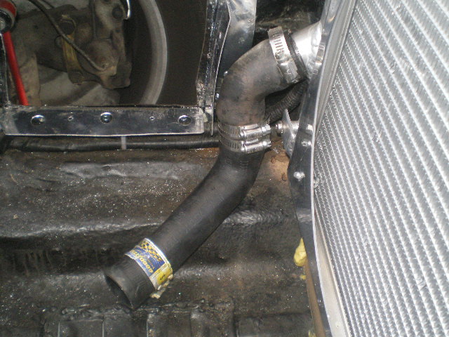 Made this copper coupling piece so I could have the line exposed once the plenum is in place. 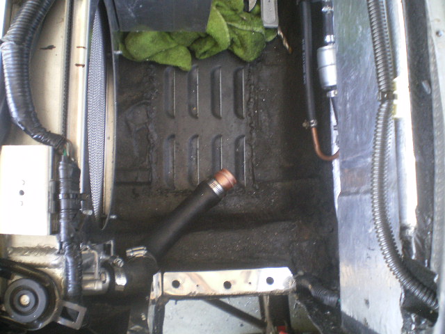 The left fan is re-fitted for what I hope is a very long time. A 3/4 x .125 piece of angle is riveted to the back wall so the top piece has several attach points. 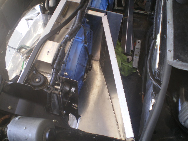 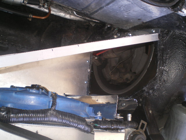 Then the top piece is cut and attached to check fit. The clecoes will remain in place during initial testing. I had planned on installing plate nuts with countersunk SS screws but now I'm leaning towards pop rivets. I can drill those out faster than I can remove those soft SS screws. (IMG:style_emoticons/default/happy11.gif) I need to install and connect the new coolant lines before I build the right side plenum. 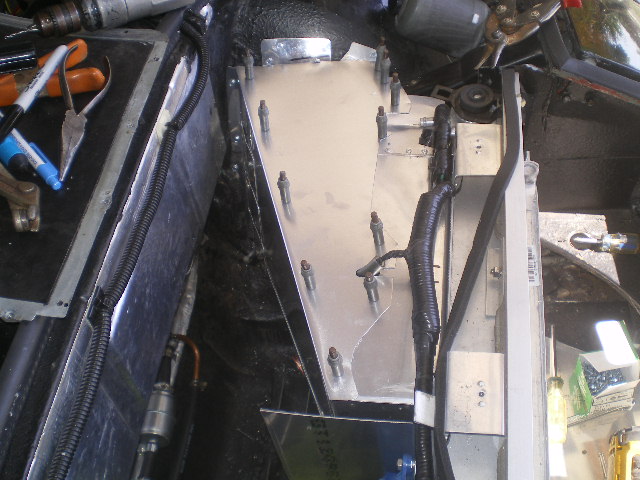 |
| 76-914 |
 Jul 8 2017, 07:32 PM Jul 8 2017, 07:32 PM
Post
#760
|
|
Repeat Offender & Resident Subaru Antagonist           Group: Members Posts: 13,634 Joined: 23-January 09 From: Temecula, CA Member No.: 9,964 Region Association: Southern California 
|
Pieces are all cut and mated. Just need to remount the fan and a general clean up before reassembling. I'll silicone inside where skin surfaces are joined to make it air tight. However, I can't go further until some A/C and radiator hose fittings arrive. Should be this week. Here are a few pics in the rough to give you a general idea of the shape. I'll post the final product and some measurements if anyone wants them. (IMG:style_emoticons/default/beerchug.gif)
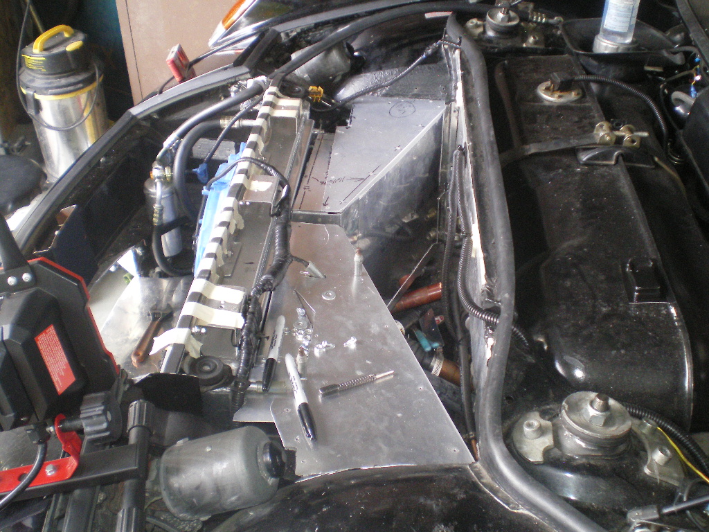 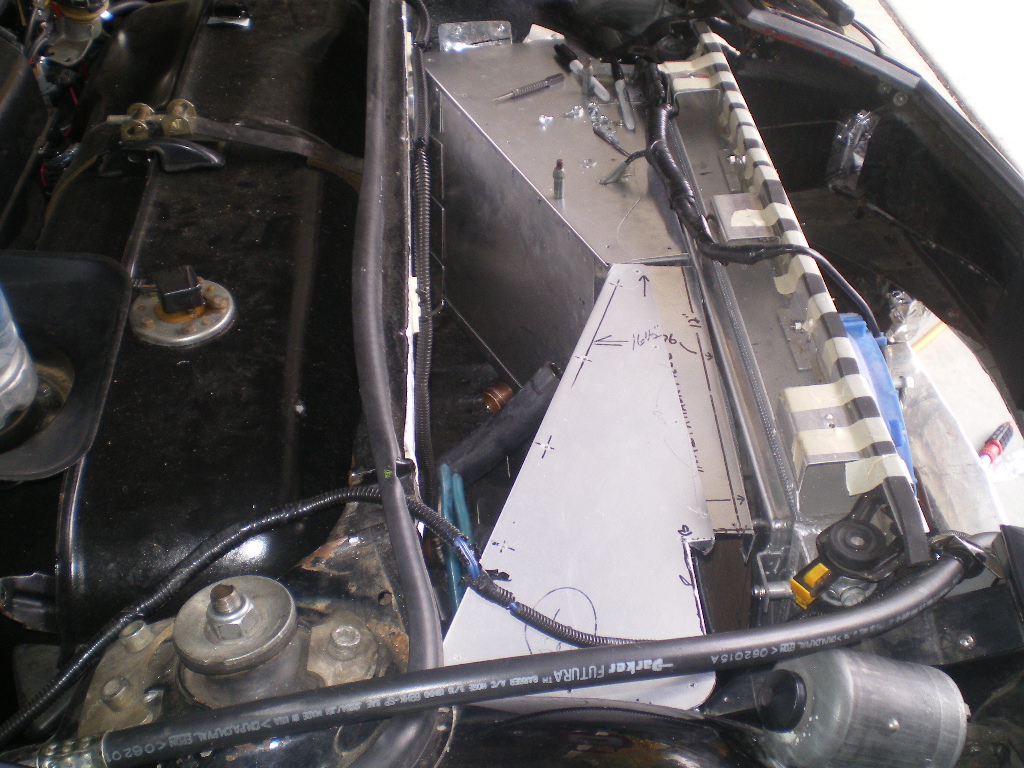 |
  |
1 User(s) are reading this topic (1 Guests and 0 Anonymous Users)
0 Members:

|
Lo-Fi Version | Time is now: 23rd November 2024 - 05:05 PM |
Invision Power Board
v9.1.4 © 2024 IPS, Inc.


