|
|
|
Porsche, and the Porsche crest are registered trademarks of Dr. Ing. h.c. F. Porsche AG.
This site is not affiliated with Porsche in any way. Its only purpose is to provide an online forum for car enthusiasts. All other trademarks are property of their respective owners. |
|
|

  |

| Dr Evil |
 Nov 17 2004, 02:57 AM Nov 17 2004, 02:57 AM
Post
#1
|
|
Send me your transmission!  Group: Members Posts: 23,032 Joined: 21-November 03 From: Loveland, OH 45140 Member No.: 1,372 Region Association: MidAtlantic Region |
Well, I promised a while ago that if I could get ahold of a program for drawing scematics I would make some quick troubleshooting diagrams for us all. I got Visio2000 and it seems to be adequate for this so I will start posting my schematics as I draw them. If no one is interested let me know and I'll just keep this to myself. Just thought that I might help.
First is the circuit that causes much head ach with the D-jet system. "Why is my fuel pump fuse blowing?" Usually it is because the Auxilary Air Valve is shorting to the block at the plug, but here are the other things involved. This is of the fuse/relay panel in the left engine compartment: B+ is the positive side of the battery. The pointy parts at the end of some of the lines are ground. Consider all grounds to be the same place and to be connected to the negative side of the battery through the cars body. Ask questions if you need clarification. Attached thumbnail(s) 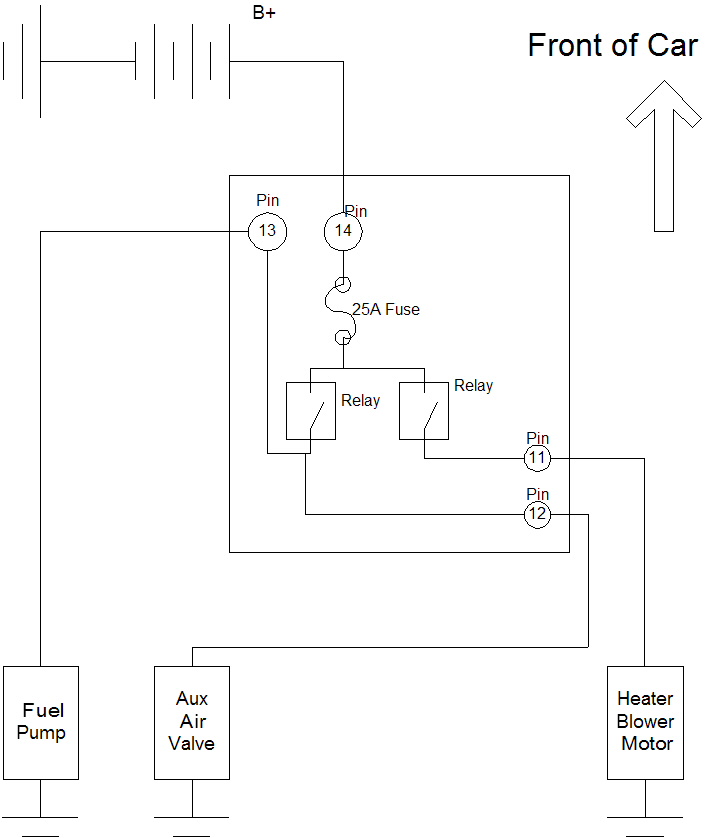
|
   |

 
|
| Dr Evil |
Nov 17 2004, 02:59 AM
Post
#2
|
|
Send me your transmission! Group: Members Posts: 23,032 Joined: 21-November 03 From: Loveland, OH 45140 Member No.: 1,372 Region Association: MidAtlantic Region |
I am looking for ideas for other trouble circuits to draw bare bones. Any suggestions?
-Next is the outer lights |
|
|
|
| Carlitos Way |
Nov 17 2004, 11:37 AM
Post
#3
|
|
I did it MY WAY Group: Members Posts: 1,337 Joined: 14-September 04 From: Simi Valley, CA Member No.: 2,757 Region Association: Southern California |
Great idea! Looking forward to seeing more.
|
|
|
|
| Mueller |
Nov 17 2004, 01:52 PM
Post
#4
|
|
914 Freak! Group: Members Posts: 17,150 Joined: 4-January 03 From: Antioch, CA Member No.: 87 Region Association: None |
I like it !!!!
how about the headlight circut ?? |
|
|
|
| Dr Evil |
Nov 17 2004, 01:58 PM
Post
#5
|
|
Send me your transmission! Group: Members Posts: 23,032 Joined: 21-November 03 From: Loveland, OH 45140 Member No.: 1,372 Region Association: MidAtlantic Region |
- Head / Running lights
- Turn Signals - Reverse light circuit Coming up as soon as I get time. THX |
|
|
|
| lapuwali |
Nov 17 2004, 03:36 PM
Post
#6
|
|
Not another one! Group: Benefactors Posts: 4,526 Joined: 1-March 04 From: San Mateo, CA Member No.: 1,743 |
Before you get too far along, I'd like to point everyone to what I consider to be the finest home-brewed wiring diagram available:
Dave Hillman's 912 diagram Click on the layered PDF link. Wiring colors on the diagram help a lot. Having the layers allows you to only see the part of the system you're interested in. Dave has some info on how he created this diagram on the site. I know he started with the factory b & w wiring diagram and went to town. Any effort is, of course, appreciated (and perhaps we all need to pitch in on this and add it to the tech pages), but Dave's work is the best I've seen, and is a great target to shoot for. |
|
|
|
| jim_hoyland |
Nov 17 2004, 06:11 PM
Post
#7
|
|
Get that VIN ? Group: Members Posts: 9,418 Joined: 1-May 03 From: Sunset Beach, CA Member No.: 643 Region Association: Southern California |
I would like to see the headlight system. I want to have my switch set up so only the orange corner lights ( front and rear) come on first; then the license plate, reds, and headlights come on with full on.
If your diagram can help me make this change, it would be greatly appreciated. Jim |
|
|
|
| mskala |
Nov 17 2004, 07:34 PM
Post
#8
|
|
R Group: Members Posts: 1,925 Joined: 2-January 03 From: Massachusetts Member No.: 79 Region Association: None |
Art Zapf also has primo 914-6 diagrams.
|
 |
|
| Dr Evil |
Nov 17 2004, 08:51 PM
Post
#9
|
|
Send me your transmission! Group: Members Posts: 23,032 Joined: 21-November 03 From: Loveland, OH 45140 Member No.: 1,372 Region Association: MidAtlantic Region |
Well, anyone could go buy the book and get that diagram. That is not my intention. My intention is to make diagrams that are the limited systems. Most folks have no interest in looking a a multi colored spyder web to chase wires. That is where this would come in. Thanks for the links though. I will keep adding proposed and actual diagrams, as I get time, to the original list.
Thanks for the ideas, fellas. |
|
|
|
| jim_hoyland |
Nov 19 2004, 08:58 AM
Post
#10
|
|
Get that VIN ? Group: Members Posts: 9,418 Joined: 1-May 03 From: Sunset Beach, CA Member No.: 643 Region Association: Southern California |
I like the idea, could you label more for us non-tech types.
|
|
|
|
| Dr Evil |
Nov 19 2004, 02:59 PM
Post
#11
|
|
Send me your transmission! Group: Members Posts: 23,032 Joined: 21-November 03 From: Loveland, OH 45140 Member No.: 1,372 Region Association: MidAtlantic Region |
Jim,
I put a little more detailed description in the post attached to the first diagram. Is that what you meant? Glad to help. I am working on the headlight circuit right now, but it is pretty complicated so it is hard to make clearer. THX |
|
|
|
| Dr Evil |
Dec 4 2004, 01:53 AM
Post
#12
|
|
Send me your transmission! Group: Members Posts: 23,032 Joined: 21-November 03 From: Loveland, OH 45140 Member No.: 1,372 Region Association: MidAtlantic Region |
Here is the first sub circuit of the headlight realy/motor circuit.
The relay pins are as follows: 85 - Headlight Motor auto actuator (up down) 86 - Ground 87a - Ground connected to 86 87 - supply side (opposite side of battery power) of fuse 12 30 - Headlight motor power Numbers in circles in the blocks are designators from the Haynes manual. This is a seriously watered down diagram for the novice. It should get you in the right direction. Consult your Haynes manual if this doesn't do it for ya. Attached thumbnail(s) 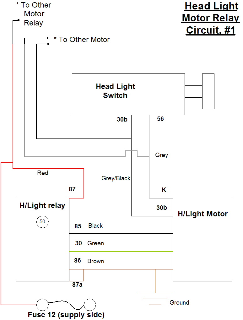
|
|
|
|
| Dr Evil |
Dec 4 2004, 02:46 AM
Post
#13
|
|
Send me your transmission! Group: Members Posts: 23,032 Joined: 21-November 03 From: Loveland, OH 45140 Member No.: 1,372 Region Association: MidAtlantic Region |
Headlight Lighting Circuit.
Wire colors are as follows: Fuses 1 and 2 to 56a (left and right lights perspectively) = White Fuses 3 and 4 to 56b (left and right lights perspectively) = Yellow Ground for bulbs = Brown Fuses 1 and 2 to "f" on realy = White Fuses 3 and 4 to 56a on relay = Yellow From non designated pin on relay to headlight switch Pin 56= Red/White From 56 on relay to ignition switch pin "S" = Yellow/Red Fuses Fuse 1 = High beam left Fuse 2 = High beam right Fuse 3 = Low beam left Fuse 4 = Low beam right The numbers in circles are the component designator numbers from the Haynes manual. *The instraments get their power from fuse 1 on the relay side. Attached thumbnail(s) 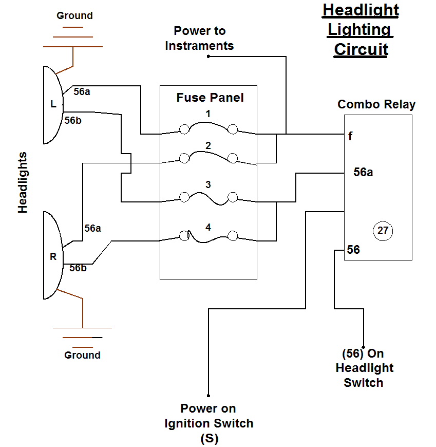
|
|
|
|
| Teknon |
Dec 4 2004, 09:33 AM
Post
#14
|
|
The more I learn the dumber i think I am Group: Members Posts: 357 Joined: 10-August 04 From: Denver, Colorado Member No.: 2,505 Region Association: Rocky Mountains |
Exellent Doctor, Could you posibly make me a schematic for the rear window defroster. Joe
|
|
|
|
| ThinAir |
Dec 4 2004, 12:43 PM
Post
#15
|
|
Best friends Group: Members Posts: 2,553 Joined: 4-February 03 From: Flagstaff, AZ Member No.: 231 Region Association: Southwest Region |
This is great stuff! What I particularly appreciate is the simplicity of it and how closely it resembles the physical stuff that you actually have to handle when you work on the car. Current diagrams drive me crazy, never have figured them out. What I need are things that translate easily to the physical items in the car. Great work!
|
|
|
|
| Dr Evil |
Dec 4 2004, 03:12 PM
Post
#16
|
|
Send me your transmission! Group: Members Posts: 23,032 Joined: 21-November 03 From: Loveland, OH 45140 Member No.: 1,372 Region Association: MidAtlantic Region |
Thanks guys!
QUOTE it resembles the physical stuff that you actually have to handle when you work on the car Thats what I am trying for, I am glad to see that it is working out. I'll draw up a rar heater defroster diagram when I get time. I still have a fog light one to draw and post. |
|
|
|
| Dr Evil |
Dec 5 2004, 04:29 AM
Post
#17
|
|
Send me your transmission! Group: Members Posts: 23,032 Joined: 21-November 03 From: Loveland, OH 45140 Member No.: 1,372 Region Association: MidAtlantic Region |
Ask and you shall recieve (IMG:style_emoticons/default/smile.gif)
Here is all I got from the manual: -Yellow/Red wire goes to defroster switch (hot when on). -Green wire is the power to the defroster (ground must be on the other side of the defroster -Pin 14 is straight from the battery. It is always hot. It goes to the 25A fuse. -Pin 10 is ground The relay for the defroster is (52) the one that is most forward on the board. Any questions, just ask. Attached thumbnail(s) 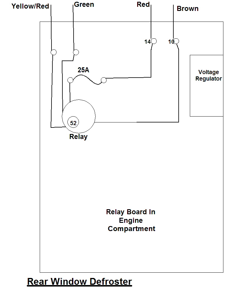
|
|
|
|
| balthazar |
Dec 19 2004, 10:21 PM
Post
#18
|
|
P-car junkie Group: Members Posts: 161 Joined: 23-March 03 From: Arvada, Colorado Member No.: 464 |
Perfect! I would like to see the turn signal circuit! Also would be great to have the rest of the lighting as well! (IMG:http://www.914world.com/bbs2/html/emoticons/smilie_pokal.gif)
|
|
|
|
|
1 User(s) are reading this topic (1 Guests and 0 Anonymous Users)
0 Members:

|
Lo-Fi Version | Time is now: 27th September 2024 - 12:34 PM |
Invision Power Board
v9.1.4 © 2024 IPS, Inc.