|
|
|
Porsche, and the Porsche crest are registered trademarks of Dr. Ing. h.c. F. Porsche AG.
This site is not affiliated with Porsche in any way. Its only purpose is to provide an online forum for car enthusiasts. All other trademarks are property of their respective owners. |
|
|


| LotusJoe |
 Feb 18 2010, 09:43 PM Feb 18 2010, 09:43 PM
Post
#1
|
|
Europa Twink Driver  Group: Members Posts: 406 Joined: 30-November 09 From: Southern California Member No.: 11,085 Region Association: Southern California |
I have built an engine stand for my 1973 2.0 engine. I'm in the process of trying to wire everything up to start the motor. Can anyone help me out with the what wires I need to supply power to the control module?
(IMG:http://photos-e.ak.fbcdn.net/hphotos-ak-snc3/hs180.snc3/20736_1346662951457_1377807605_959608_6834010_n.jpg) (IMG:http://photos-d.ak.fbcdn.net/hphotos-ak-snc3/hs200.snc3/20736_1346663111461_1377807605_959612_7956026_n.jpg) (IMG:http://photos-c.ak.fbcdn.net/hphotos-ak-snc3/hs180.snc3/20736_1346662991458_1377807605_959609_5643660_n.jpg) This photo show a small group of wires that plugs onto the module and then to (I think various locations on the engine). Looks like a pair goes to the back-up switch on the transmission, but I'm not sure about the rest of them. Any help is greatly appreciated Thanks Joe ( The Newbie to the 914 world) |
   |

 
|
  |
Replies
| jcd914 |
Feb 19 2010, 11:13 AM
Post
#2
|
|
Advanced Member Group: Members Posts: 2,081 Joined: 7-February 08 From: Sacramento, CA Member No.: 8,684 Region Association: Northern California |
Here is what I have for the 14 pin connector for the Relay Panel.
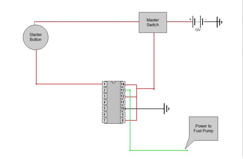
1 - Power in from starter switch 2 - Power/ground for Alternator light 3 - 4 - 5 - From Oil Press Light 6 - 7 - Signal to Tach 8 - Power in from Ignition switch 9 - To Heater Fan Switch 10 - To Main Ground 11 - Power out to Heater Fan 12 - Power in from Battery 13 - Power out to Fuel Pump 14 - Power in from Battery Jim |
|
|
|
| LotusJoe |
Feb 19 2010, 12:09 PM
Post
#3
|
|
Europa Twink Driver Group: Members Posts: 406 Joined: 30-November 09 From: Southern California Member No.: 11,085 Region Association: Southern California |
QUOTE(jcd914 @ Feb 19 2010, 09:13 AM)  Here is what I have for the 14 pin connector for the Relay Panel. 1 - Power in from starter switch 2 - Power/ground for Alternator light 3 - 4 - 5 - From Oil Press Light 6 - 7 - Signal to Tach 8 - Power in from Ignition switch 9 - To Heater Fan Switch 10 - To Main Ground 11 - Power out to Heater Fan 12 - Power in from Battery 13 - Power out to Fuel Pump 14 - Power in from Battery Jim Thanks Jim, that's exactly what I was looking for. Now I can finish the wiring for the engine stand. |
|
|
|
| LotusJoe |
Feb 19 2010, 04:53 PM
Post
#4
|
|
Europa Twink Driver Group: Members Posts: 406 Joined: 30-November 09 From: Southern California Member No.: 11,085 Region Association: Southern California |
I have made a diagram of the pins I think need to be connected in order to start the engine. Does this look correct?
 |
|
|
|
Posts in this topic
 LotusJoe Setting up to bench test 2.0 engine Feb 18 2010, 09:43 PM
 detoxcowboy I am unsure whihc year 2.0 you have and which harn... Feb 18 2010, 10:21 PM
 LotusJoe I'm unable to get that link to work. Think may... Feb 18 2010, 10:38 PM detoxcowboy
I'm unable to get that link to work. Think ma... Feb 18 2010, 10:42 PM LotusJoe Thanks, I got the link to work. Now I only need a ... Feb 19 2010, 01:47 AM detoxcowboy
There you go 73-76 ignition harness! click t... Feb 18 2010, 10:27 PM LotusJoe Thanks detoxcowboy for the drawing. That takes car... Feb 18 2010, 10:41 PM Cap'n Krusty Or you could just look at the factory wiring diagr... Feb 19 2010, 09:18 AM type47
factory wiring diagrams over on the Pelican Part... Feb 19 2010, 09:21 AM LotusJoe Thanks to all who responded on this thread. The en... Feb 25 2010, 08:09 PM
LotusJoe I'm unable to get that link to work. Think may... Feb 18 2010, 10:38 PM detoxcowboy
I'm unable to get that link to work. Think ma... Feb 18 2010, 10:42 PM LotusJoe Thanks, I got the link to work. Now I only need a ... Feb 19 2010, 01:47 AM detoxcowboy
There you go 73-76 ignition harness! click t... Feb 18 2010, 10:27 PM LotusJoe Thanks detoxcowboy for the drawing. That takes car... Feb 18 2010, 10:41 PM Cap'n Krusty Or you could just look at the factory wiring diagr... Feb 19 2010, 09:18 AM type47
factory wiring diagrams over on the Pelican Part... Feb 19 2010, 09:21 AM LotusJoe Thanks to all who responded on this thread. The en... Feb 25 2010, 08:09 PM |
2 User(s) are reading this topic (2 Guests and 0 Anonymous Users)
0 Members:

|
Lo-Fi Version | Time is now: 27th September 2024 - 10:20 AM |
Invision Power Board
v9.1.4 © 2024 IPS, Inc.