|
|
|
Porsche, and the Porsche crest are registered trademarks of Dr. Ing. h.c. F. Porsche AG.
This site is not affiliated with Porsche in any way. Its only purpose is to provide an online forum for car enthusiasts. All other trademarks are property of their respective owners. |
|
|


| JamesM |
 Jan 20 2021, 02:08 AM Jan 20 2021, 02:08 AM
Post
#1
|
|
Senior Member  Group: Members Posts: 1,965 Joined: 6-April 06 From: Kearns, UT Member No.: 5,834 Region Association: Intermountain Region |
and in with.... well... MORE MEGASQUIRT!!!!
Little back story here and then a bunch of pictures. I have several 914s but the one I refer to as my "autocross car" (which started as my daily driver in the late 90s) has AFAIK been running Megasquirt possibly longer than any other 914 on the planet. For the last 17 or so years it has been the platform I have experimented on and in that time has seen at least 5 different Megasquirt configurations across 2 different motors. This ongoing project is one of the reasons I am so intimately familiar with both Megasquirt and D-jet as to date all the configurations I have ran in this particular car have done so using an unmodified d-jet wiring harness which required a good deal of study/reverse engineering. At one point my focus was on making a completely stealth setup (looks exactly like a d-jet system) which I did, however as the Megasquirt feature set improved over the last 17 years and my focus moved more towards the overall performance of the system I kept hastily hacking in additional features (mainly having to do with the addition of full ignition control and O2 feedback) and an ancillary rats nest started to grow around my once stock looking system. Remembering what all extra wires plugged in where started to become tedious, especially if I would go extended periods without doing anything to them. With the desire to change/add additional elements to the system I decided I needed to just bite the bullet and build a whole new system from the ground up. Technically i have been planning (sitting on the parts) to do this for years but as the current system ran just fine it was lower on my priority list. The whole COVID situation has allowed me lots of time to get pretty much every other project done on all my other cars, so it was time to move forward with this one. Details on the system coming out: ECU: Completely custom (see homemade) ECU board based on the MS1 2.2 circuit design however I modified the injector circuits to supply a switched current rather than a switched ground in order to work with the D-jet harness, and then later retrofitted an MS2 CPU to expand the feature set. Injectors: Stock 914 2.0 off a stock pressure regulator Ignition: Full timing control currently triggered via Pertronix pickup modified with a pullup resistor in a stock distributor with a locked out mechanical advance. Output is then from the MS system to a Mallory 6AL CD box (this was a really easy way to trigger a coil from Megasquirt back in the day as it can take a logic level input) The Goals of this project 1. Cleaning up the engine bay wiring and simplifying the connections (single harness plug to the stock relay board and thats it!) 2. Move to a 36-1 crank trigger 3. Add a 2nd MAP sensor for real time barometric correction (we have some high mountains around these parts) 4. Eliminate the distributor and CD ignition box 5. Swap the LC1 wideband controller for the newer(and smaller) LC2 6. Use a modern Fuel Injector with known voltage offset values (will get more into this later) 6.Stop using the d-jet harness (Will elaborate on this as well) WHY???!?! Back at the end of the 90s I was a d-jet purist, carbs to me have always been a step back and never an option for me, so when my d-jet system started acting up one of the things I did at the time was to purchase a new wiring harness made by a company called R.E.S. Systems. This was the only NEW replacement harness available at the time and is still an absolute work of art as far as i am concerned, overbuilt like no other d-jet harness you have ever seen. Needless to say it was not a piece I wanted to take off the car and replace with whatever homemade harness my limited experience could coble together at the time, so i invested time in figuring out how I could retrofit an MS system (also very new at the time ~2003) into an otherwise stock d-jet setup. Now, while doing this does result in a system that works as well as a good d-jet system I am here to tell everyone once and for all that D-jet does have some inherent faults with its design and that those faults become very apparent when you can see them in data logs and also when you realize that a lot of the known d-jet operational "quirks" follow you when running a modern ECU on the d-jet harness. The nicest d-jet harness in the world does not eliminate these issues, they are inherent in the design. So in the interest of having the best running car possible a new design harness is needed, which is fine by me as i want to integrate everything into a single harness anyways. Other things to come with the new build, modern 43 PSI injectors should atomize the fuel better, in addition having known voltage offset tables is mandatory to achieve the most consistant tune across all operating conditions. The change to the 36-1 crank trigger is for increased accuracy but also to improve ease of cold starts over the 4 tooth cam trigger. Getting rid of the distributor was not mandatory but I had an idea for a new setup I wanted to try out, so its getting worked in the changes as well. Had a week of vacation time to burn after Christmas that seemed like the perfect time to get this all done so... on with the show... |
   |

 
|
  |
Replies
| JamesM |
Jan 20 2021, 02:36 AM
Post
#2
|
|
Senior Member Group: Members Posts: 1,965 Joined: 6-April 06 From: Kearns, UT Member No.: 5,834 Region Association: Intermountain Region |
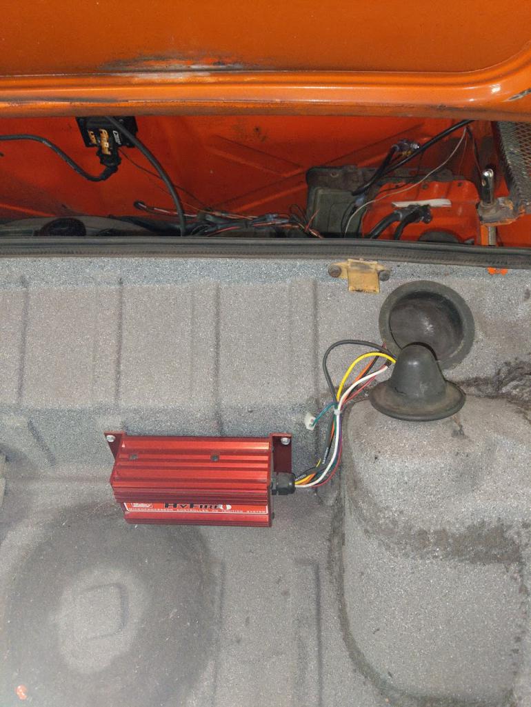
Factor contributing to the rats nest, coming out!
 And the ridiculous amount of wiring connection the LC1 wideband needed 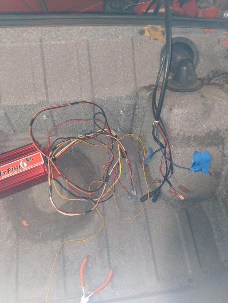 |
|
|
|
| JamesM |
Jan 20 2021, 02:41 AM
Post
#3
|
|
Senior Member Group: Members Posts: 1,965 Joined: 6-April 06 From: Kearns, UT Member No.: 5,834 Region Association: Intermountain Region |
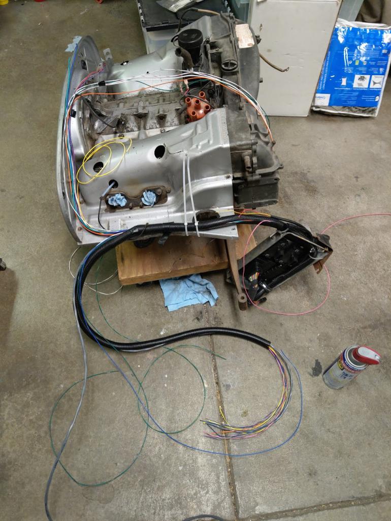
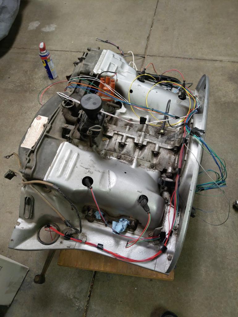
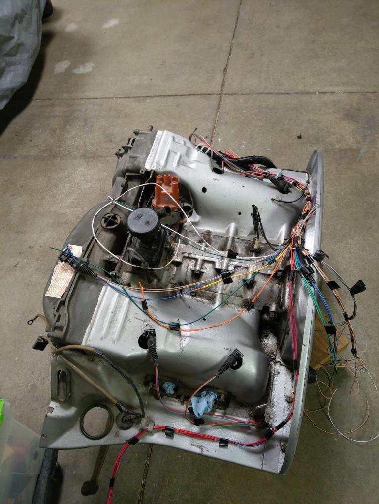
and now the part that makes me sad... pulling the beautiful RES Systems D-jet harness. Almost 20 years later this thing still looks practically brand new. just a tank of a wiring harness with every connector and junction properly sealed to water proof it and every connector labeled.
If i don't wind up putting this in another car it will probably go up on my garage wall as art! 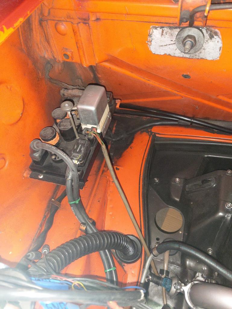 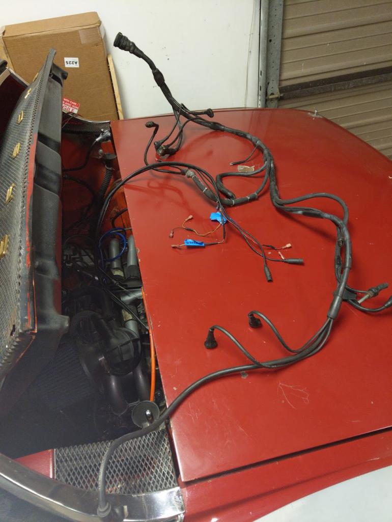 |
|
|
|
| JamesM |
Jan 20 2021, 02:48 AM
Post
#4
|
|
Senior Member Group: Members Posts: 1,965 Joined: 6-April 06 From: Kearns, UT Member No.: 5,834 Region Association: Intermountain Region |
New ECU is just going to be an off the shelf Microsquirt. No more 12 hours of labor custom building circuit boards for me!
I had a gutted d-jet ECU case from another one of my previous MS builds, so i re-purposed that as a bracket for the ECU, both MAP sensors and the new (much smaller) LC2 wideband controller. 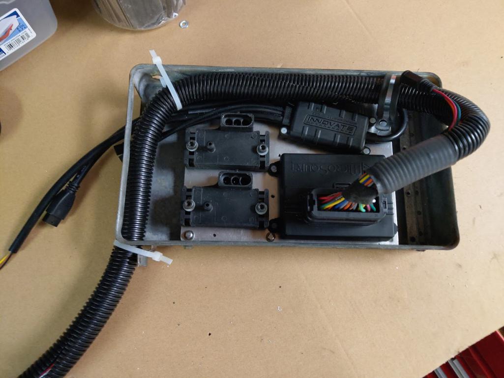 My old MS 2.2 custom board d-jet harness compatible ECU next to the new Microsquirt setup, not quite as trick looking but I may revisit that later. 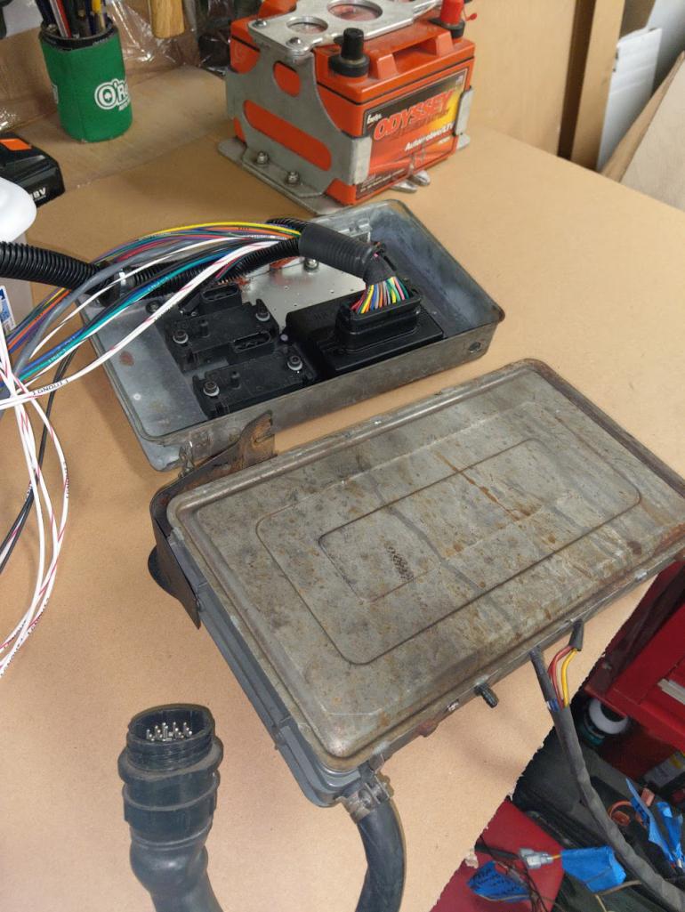 |
|
|
|
| JamesM |
Jan 20 2021, 03:00 AM
Post
#5
|
|
Senior Member Group: Members Posts: 1,965 Joined: 6-April 06 From: Kearns, UT Member No.: 5,834 Region Association: Intermountain Region |
And now the REALLY fun part... putting this in there... and trying to make something out of this new mess!
 Laying it out as an initial test to get a rough idea of spacing from the ECU bracket to the relay board. Not looking complicated at all at this point (IMG:style_emoticons/default/biggrin.gif) 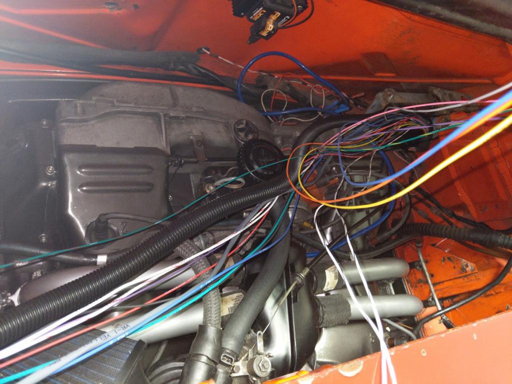 Making the runs for the injectors and MAP sensors Not using pigtails for this build, everything is color coded un-spliced wires out to crimped pin connectors. Minimizing the the junctions minimizes the potential problems. NO SOLDER! 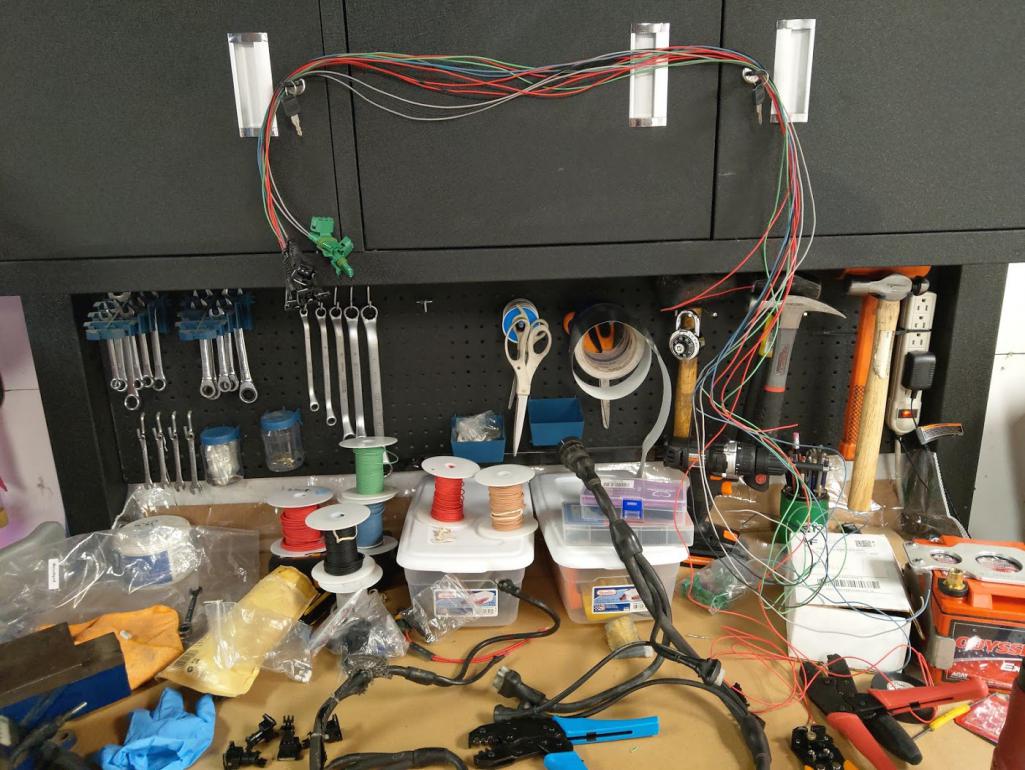 |
|
|
|
| JamesM |
Jan 20 2021, 03:15 AM
Post
#6
|
|
Senior Member Group: Members Posts: 1,965 Joined: 6-April 06 From: Kearns, UT Member No.: 5,834 Region Association: Intermountain Region |
After i got the spacing relative to the engine I pulled it back out to mock it up on a spare engine on the floor.
   Decided to leave all the unused wires in the Microsquirt harness intact at full length in case I wanted to add something else later (I tend to do that) so they got sealed up with liquid electrical tape and cover in heat shrink. A couple wires im not currently using i still ran out to where i may use them, as I already have some addition upgrade in mind (IMG:style_emoticons/default/biggrin.gif) 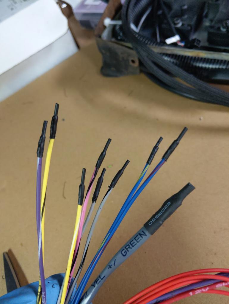 Pulled back on the bench to get everything sheathed and connectors installed. 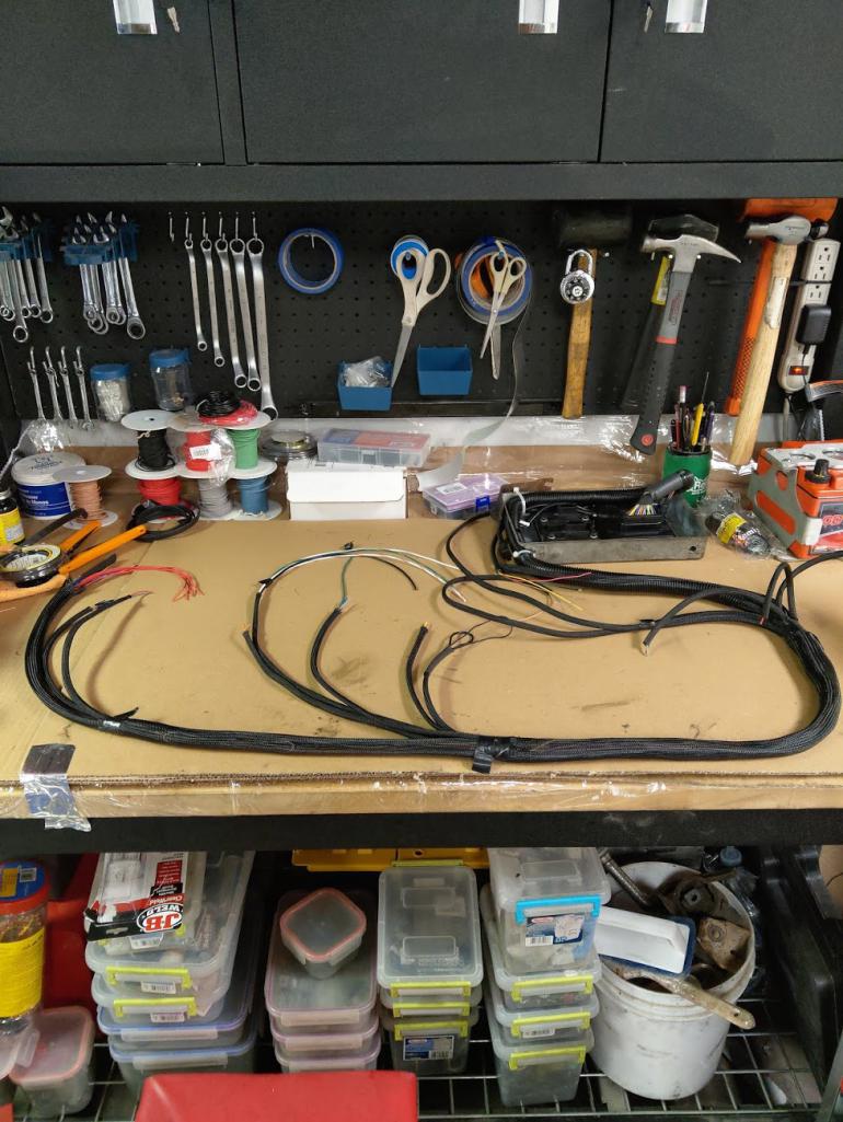 Just about ready to go, just need to add fuses inline on the power circuits at the relay board and finish sizing the wire lengths to my coil experiment. I was going to go with a familiar setup there but i just cant help myself and had an idea for something new!! Not nearly as pretty as the RES harness, but i think i did ok. May revisit it again later as im not super happy with the braided sleeve. 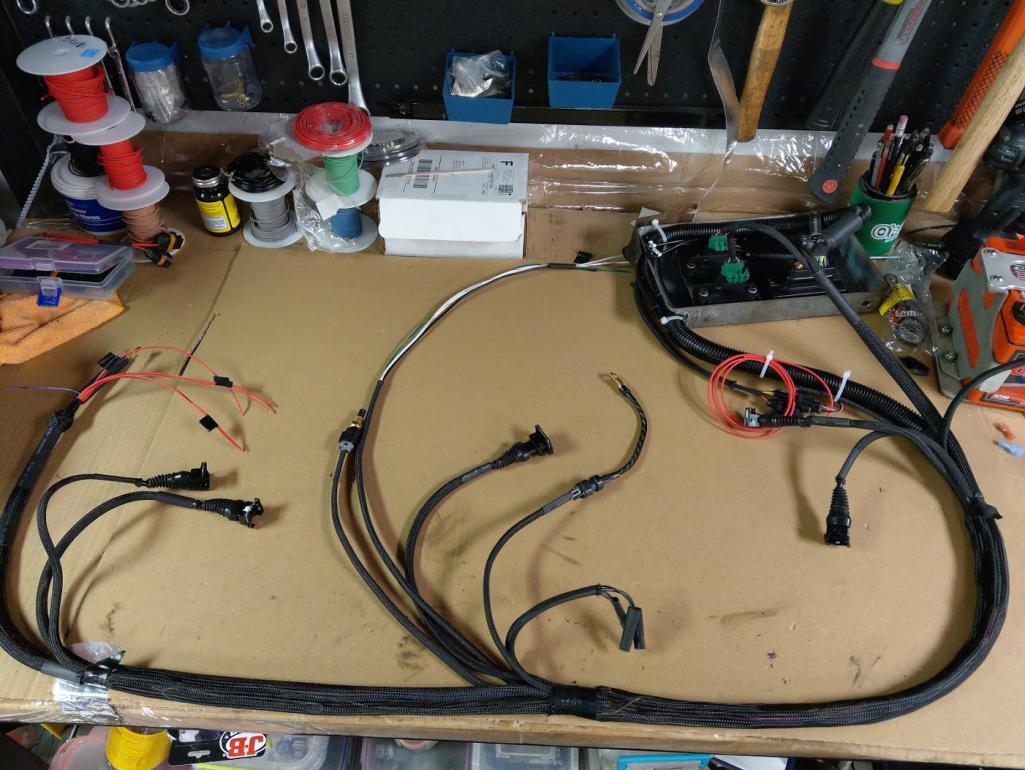 |
|
|
|
| JamesM |
Jan 20 2021, 03:32 AM
Post
#7
|
|
Senior Member Group: Members Posts: 1,965 Joined: 6-April 06 From: Kearns, UT Member No.: 5,834 Region Association: Intermountain Region |
And now for the next surprise idea(s).
I want to keep the plug wires all running through their stock locations so I took an idea (and a spare distributor) down to Ye local house of 914 art (AKA PMB) and had them Frankenstein this piece up for me. They did this way prettier than I ever would have been able to. 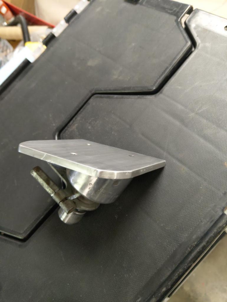 Why you ask.... 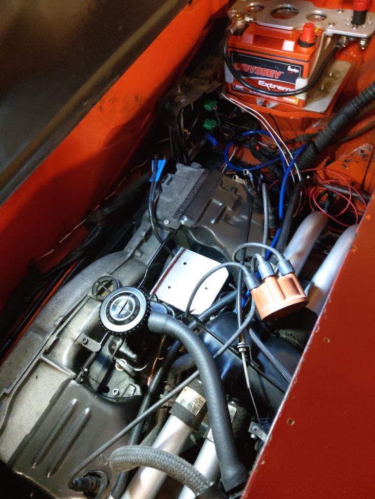 I had a very specific coil pack in mind. Looks almost like it was designed to go exactly there. 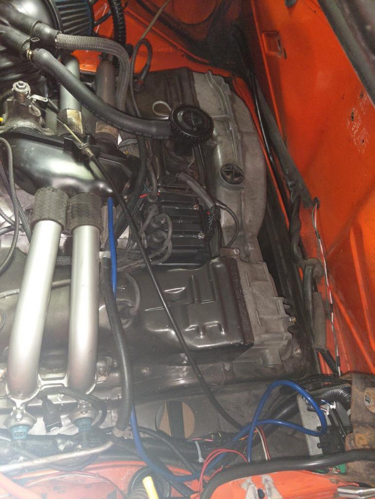 |
|
|
|
| GregAmy |
Jan 20 2021, 08:18 AM
Post
#8
|
|
Advanced Member Group: Members Posts: 2,385 Joined: 22-February 13 From: Middletown CT Member No.: 15,565 Region Association: North East States |
|
|
|
|
| JamesM |
Jan 20 2021, 10:32 AM
Post
#9
|
|
Senior Member Group: Members Posts: 1,965 Joined: 6-April 06 From: Kearns, UT Member No.: 5,834 Region Association: Intermountain Region |
QUOTE(GregAmy @ Jan 20 2021, 07:18 AM)  You would have to ask @Eric_Shea about that one. His guys at PMB did the fabrication work for me as I didn't have the necessary tools to do it myself. I brought them a core distributor and an idea and they returned that beautiful piece. In the end it is just a hacked up cheap distributor (i wouldn't waste a d-jet one) with a plate welded on it but the result is exactly what I was looking for. Really nice for a one-off part but im not sure it would make sense to do it this way in a production environment given the labor and need to sacrifice a distributor. If someone wanted to produce these in any volume I suspect it might make more sense to just machine the whole thing. |
|
|
|
| GregAmy |
Jan 20 2021, 10:41 AM
Post
#10
|
|
Advanced Member Group: Members Posts: 2,385 Joined: 22-February 13 From: Middletown CT Member No.: 15,565 Region Association: North East States |
QUOTE(JamesM @ Jan 20 2021, 11:32 AM) You would have to ask @Eric_Shea about that one. His guys at PMB did the fabrication work for me as I didn't have the necessary tools to do it myself... Understand. I use the VAG IGN-4 ignitor/coil and it work great. However, my initial installation was on a steel plate I fabbed that sat across the disty retention stud and two engine tin screws. As the weather got hotter this Spring I started getting a lot of ignition cut-outs...short answer was the IGN4 was overheating, sitting on that plate mounted directly to the engine block. Short term I moved it to sitting on top of the cooling fan, and I've yet to come up with an elegant replacement solution. I like yours and suggest that may keep the coil far enough away from the engine heat to allow air to circulate around it. I've got an old 009 hanging about, might try fabbing something. |
|
|
|
| JamesM |
Jan 20 2021, 12:52 PM
Post
#11
|
|
Senior Member Group: Members Posts: 1,965 Joined: 6-April 06 From: Kearns, UT Member No.: 5,834 Region Association: Intermountain Region |
QUOTE(GregAmy @ Jan 20 2021, 09:41 AM) QUOTE(JamesM @ Jan 20 2021, 11:32 AM) You would have to ask @Eric_Shea about that one. His guys at PMB did the fabrication work for me as I didn't have the necessary tools to do it myself... Understand. I use the VAG IGN-4 ignitor/coil and it work great. However, my initial installation was on a steel plate I fabbed that sat across the disty retention stud and two engine tin screws. As the weather got hotter this Spring I started getting a lot of ignition cut-outs...short answer was the IGN4 was overheating, sitting on that plate mounted directly to the engine block. Short term I moved it to sitting on top of the cooling fan, and I've yet to come up with an elegant replacement solution. I like yours and suggest that may keep the coil far enough away from the engine heat to allow air to circulate around it. I've got an old 009 hanging about, might try fabbing something. Heat is one concern I have in the back of my mind for sure with this coil setup but wont know what the end result will be until it warms up and I can get it out on the road. Like i said this coil pack setup is probably the most experimental part of this build so I cant yet speak to its reliability. Assuming the coil you are running is the VAG 032 905 106B wasted spark coil? In the past I have had good results with when working with that pack however never tried it mounted where the stock distributor goes. The one issue I did observe though (and one of the reasons for trying something new) was some unusual/high rate plug wear. The plug had completely eroded the center electrode in less than a couple thousand miles. At the time I was not sure if it was due to a defective plug or the ignition system itself but after doing further reading it sounds like this is the nature of wasted spark coils due to the reverse polarity on half the plugs, band-aided by manufactures with the use of platinum plugs. Curious if you re-checked your plug gaps after running the coil for a while now? Also curious what your total dwell is when you are running? Wondering if excessive dwell may be contributing to excess heat in the coils? Wasn't able to find much specific information on either one of these packs around dwell requirements but information I was able to find on other VAG coils that was extracted from VW ECUs seems to indicate VW in general runs their coils with far less dwell than the suggestions I have seen on MS forums and manual. Given this, I aimed on the lower end of the spectrum for the initial setup and am not seeing more than 2.8ms dwell when running after voltage corrections are applied and this value may even still be high based on the VW ECU tables I have seen where they are running roughly 1/2 of that. But again, no idea really as I have not been able to find any concrete documentation. Time/experimentation will tell. So far though the coil has been cool to the touch, granted this was only ran for about 20 minutes with no load with weather in the 30s. May be a different case when autocrossing when its 105 out. One thing I considered doing when installing the pack in the first place was using spacers on the bolts between the coil and the mounting plate to allow air flow under the coil as i believe that is how some are mounted in the factory applications. Didn't have spacers on hand but i may go back and revisit that as well. ill let you know how it turns out. |
|
|
|
| GregAmy |
Jan 20 2021, 02:19 PM
Post
#12
|
|
Advanced Member Group: Members Posts: 2,385 Joined: 22-February 13 From: Middletown CT Member No.: 15,565 Region Association: North East States |
QUOTE(JamesM @ Jan 20 2021, 01:52 PM) Assuming the coil you are running is the VAG 032 905 106B wasted spark coil? ... Curious if you re-checked your plug gaps after running the coil for a while now? That's the one, and I have not re-checked spark gap. I wasn't aware of that erosion problem, but knowing that I'll check them; I've got about 2500 miles on the system so far. When I was troubleshooting the cut-out issue I ended up backing off the dwell settings from where Mario (DubShop) recommended. I'm currently running Standard Dwell, 2.2ms Nominal, 1.0ms spark duration. Runs/starts quite good; I'm figuring it would work fine with less. I have not dinkled with the battery corrections; it's at 88%@16V, 102%@14.0, 128%@12.0, 168%@10.0V. I'm running a Lithium battery so field voltage tends to run high, around 14.2-14.5V running. It runs warm to the touch after dirivng for some time, but not so hot that it will burn. But it is in the engine compartment so hard to gauge. It was wicked hot when it was mounted to the block; my infrared indicated 180* at one point. Can't really say if that was due to higher dwell or being mounted to the block, but the cut-outs stopped immediately after I moved it. @Porschef , I think it needs airflow, like James describes. @Montreal914 is building his in the same location I put mine but with spacer offsets. |
|
|
|
Posts in this topic
 JamesM Out with the Megasquirt! Jan 20 2021, 02:08 AM
 JamesM Will start with the "before" pictures, t... Jan 20 2021, 02:30 AM
 JamesM The coil pack is the biggest unknown/experiment of... Jan 20 2021, 03:50 AM
 JamesM The entirety of everything that came off the car i... Jan 20 2021, 03:53 AM JamesM Pre flight checks on the new 36-1 crank trigger lo... Jan 20 2021, 04:01 AM JamesM
[quote name='JamesM' post='2884419' date='Jan 20 ... Jan 20 2021, 05:12 PM BeatNavy James, that's excellent. Thanks for posting t... Jan 20 2021, 05:02 AM JamesM
James, that's excellent. Thanks for posting ... Jan 20 2021, 11:57 AM Porschef :popcorn: :beer2: Jan 20 2021, 05:27 AM rhodyguy Incredible! Your skills are impressive. Jan 20 2021, 07:23 AM GregAmy Sounds like we're brothers from another mother... Jan 20 2021, 08:11 AM JamesM
Sounds like we're brothers from another mothe... Jan 20 2021, 02:53 PM GregAmy
...but knowing the limitations of the design of t... Jan 20 2021, 03:45 PM JamesM
If we could find someone to fab up these harness... Jan 20 2021, 05:29 PM GregAmy I think once a 914 specific system is widely avail... Jan 21 2021, 08:05 AM JamesM
I think once a 914 specific system is widely avai... Jan 21 2021, 09:42 AM jesse7flying Wow! I'm looking for the Google translato... Jan 20 2021, 09:53 AM brant Nice !!! work James ! Jan 20 2021, 10:09 AM 914werke :headbanger: Jan 20 2021, 10:23 AM Porschef Greg, what about a phenolic block spacer, kinda li... Jan 20 2021, 11:26 AM Montreal914 Just read the whole thread! :) Super nice ins... Jan 20 2021, 03:18 PM JamesM
Here is my coil bracket I did out of ~16ga steel... Jan 20 2021, 05:44 PM 76-914 Great read James. Excellent results. I applaud you... Jan 20 2021, 07:57 PM JeffBowlsby Someone needs to speak up against what some may mi... Jan 20 2021, 08:50 PM JamesM Hey Jeff! figured I would see you here eventu... Jan 21 2021, 01:40 AM Frank S
"...Lots of advantages over stock d-jet inj... Jan 21 2021, 03:37 AM JamesM To get this thread back on an more interesting not... Jan 21 2021, 02:24 AM Frank S James,
I did not work with Microsquirt so far and... Jan 21 2021, 05:58 AM BeatNavy
James,
I did not work with Microsquirt so far an... Jan 21 2021, 07:10 AM Frank S
[quote name='Frank S' post='2884569' date='Jan 21... Jan 21 2021, 08:10 AM GregAmy I agree with Jeff's premises. And of course I ... Jan 21 2021, 08:35 AM JamesM
I agree with Jeff's premises. And of course I... Jan 21 2021, 09:44 AM
JamesM The entirety of everything that came off the car i... Jan 20 2021, 03:53 AM JamesM Pre flight checks on the new 36-1 crank trigger lo... Jan 20 2021, 04:01 AM JamesM
[quote name='JamesM' post='2884419' date='Jan 20 ... Jan 20 2021, 05:12 PM BeatNavy James, that's excellent. Thanks for posting t... Jan 20 2021, 05:02 AM JamesM
James, that's excellent. Thanks for posting ... Jan 20 2021, 11:57 AM Porschef :popcorn: :beer2: Jan 20 2021, 05:27 AM rhodyguy Incredible! Your skills are impressive. Jan 20 2021, 07:23 AM GregAmy Sounds like we're brothers from another mother... Jan 20 2021, 08:11 AM JamesM
Sounds like we're brothers from another mothe... Jan 20 2021, 02:53 PM GregAmy
...but knowing the limitations of the design of t... Jan 20 2021, 03:45 PM JamesM
If we could find someone to fab up these harness... Jan 20 2021, 05:29 PM GregAmy I think once a 914 specific system is widely avail... Jan 21 2021, 08:05 AM JamesM
I think once a 914 specific system is widely avai... Jan 21 2021, 09:42 AM jesse7flying Wow! I'm looking for the Google translato... Jan 20 2021, 09:53 AM brant Nice !!! work James ! Jan 20 2021, 10:09 AM 914werke :headbanger: Jan 20 2021, 10:23 AM Porschef Greg, what about a phenolic block spacer, kinda li... Jan 20 2021, 11:26 AM Montreal914 Just read the whole thread! :) Super nice ins... Jan 20 2021, 03:18 PM JamesM
Here is my coil bracket I did out of ~16ga steel... Jan 20 2021, 05:44 PM 76-914 Great read James. Excellent results. I applaud you... Jan 20 2021, 07:57 PM JeffBowlsby Someone needs to speak up against what some may mi... Jan 20 2021, 08:50 PM JamesM Hey Jeff! figured I would see you here eventu... Jan 21 2021, 01:40 AM Frank S
"...Lots of advantages over stock d-jet inj... Jan 21 2021, 03:37 AM JamesM To get this thread back on an more interesting not... Jan 21 2021, 02:24 AM Frank S James,
I did not work with Microsquirt so far and... Jan 21 2021, 05:58 AM BeatNavy
James,
I did not work with Microsquirt so far an... Jan 21 2021, 07:10 AM Frank S
[quote name='Frank S' post='2884569' date='Jan 21... Jan 21 2021, 08:10 AM GregAmy I agree with Jeff's premises. And of course I ... Jan 21 2021, 08:35 AM JamesM
I agree with Jeff's premises. And of course I... Jan 21 2021, 09:44 AM |
2 User(s) are reading this topic (2 Guests and 0 Anonymous Users)
0 Members:

|
Lo-Fi Version | Time is now: 27th September 2024 - 10:10 AM |
Invision Power Board
v9.1.4 © 2024 IPS, Inc.