|
|
|
Porsche, and the Porsche crest are registered trademarks of Dr. Ing. h.c. F. Porsche AG.
This site is not affiliated with Porsche in any way. Its only purpose is to provide an online forum for car enthusiasts. All other trademarks are property of their respective owners. |
|
|


| DRPHIL914 |
 Jan 21 2021, 08:55 AM Jan 21 2021, 08:55 AM
Post
#54
|
|
Dr. Phil  Group: Members Posts: 5,808 Joined: 9-December 09 From: Bluffton, SC Member No.: 11,106 Region Association: South East States |
I have been dealing with this for 12 years, a non-running defrost fan. i even pulled this out 2 years ago and rebuilt it with new flapper seals and main body seal then made sure fan turned but didnt bench test the motor or resisitors, so as a result it still does not work properly. i will be documenting this because 914rubber and Mark will soon be putting together a kit for this that includes all the hardware seals and even a motor i believe, BUT i still have problems and questions!!! so i am starting this thread to get information on diagnosing the common causes of it not working and how to fix it, and then document the rebuild and replacement of the motor, fan, resistor and maybe the control unit in dash. Others have documented the reinstallation of the fan and the cables so i will not duplicate that. and we may want to link other threads hear that have done that as well.
Mark is sending me a kit soon, so while i wait for it, i will have to get some more information about the wiring and resistors function and how to test them . I had this out last week and tested 3 different control units due to thinking that my issue was a control issue, because it runs on one speed, #2, and anything else does not work and it will then throw the fuse. most assume this would be caused by bad slider unit but i tested 3 of them and 2 are like new with no wear on the sliders , still same result. so i am suspecting the resistors /plug aparatus . If anyone has done this and cares to share how to examine and test that for proper function, lets start there. Resistor function, which lead is which and examination of the control units I will take pictures of mine tonight and post those soon. once this figured out and fixed i will do a full step bystep on reassembly too. Looking for lots of help and input on this, thanks!!! Dr. Phil |
   |

 
|
  |
Replies
| Superhawk996 |
Jan 28 2021, 07:11 PM
Post
#55
|
|
914 Guru Group: Members Posts: 6,469 Joined: 25-August 18 From: Woods of N. Idaho Member No.: 22,428 Region Association: Galt's Gulch |
Note: Really need to remove resistor pack to do this properly.
When I removed mine, I found the low speed resistor bi-metallic switch was deformed closed. However, due to corrosion on the switch it was actually reading as if the switch were open. (IMG:style_emoticons/default/lol-2.gif) Can't assume anything. 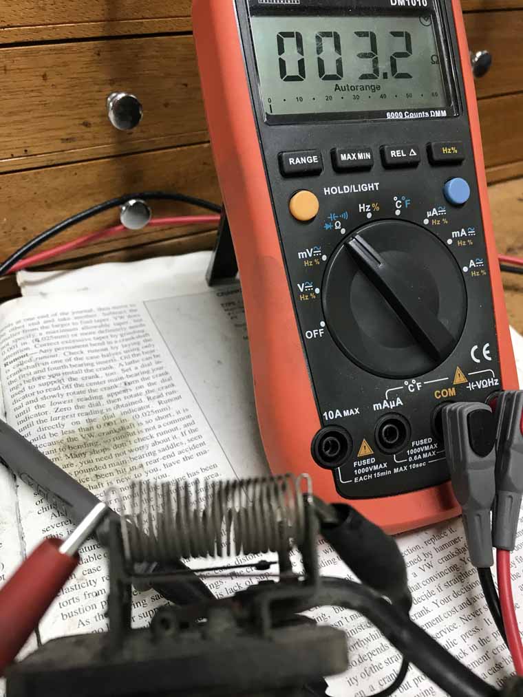 So reminder on the contact positions and keyway positions. 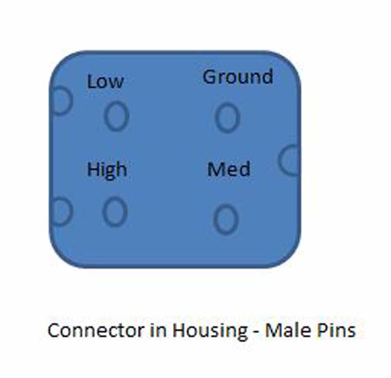 Let's roll though the verification of the resistor Here is the low speed after I filed the bi-metallic switch contact lightly with an ignition file. Because the bi-metallic switch is closed and now making contact it's measuring as a 1.1 ohm short across the resistor - bascially acting like a high speed bypass. 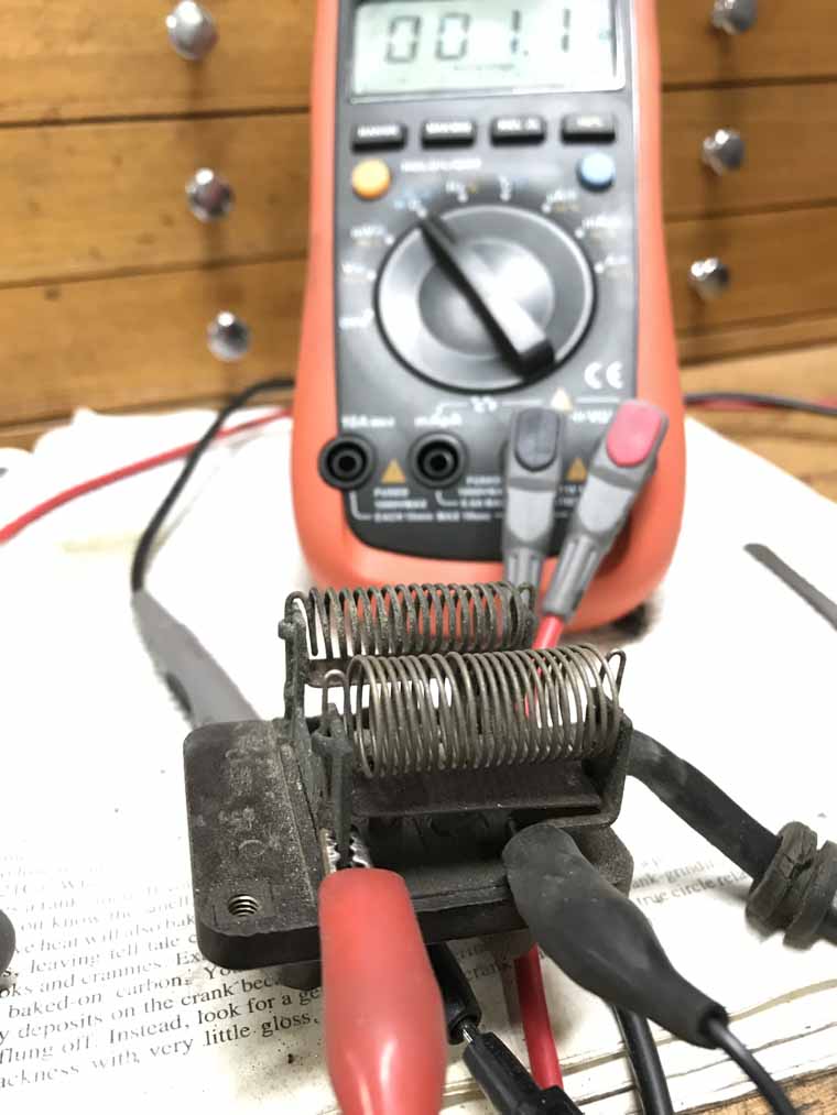 Note: from here on out I have the resistor bank leads that would normally go to the motor shorted together in same manner as @DRPHIL914 was doing previously Now low speed again with the bi-metallic switch bent back to open position with a pair of pliers to put it where it should be. 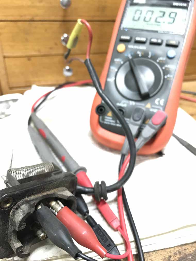 Medium speed with bi-metallic switch open 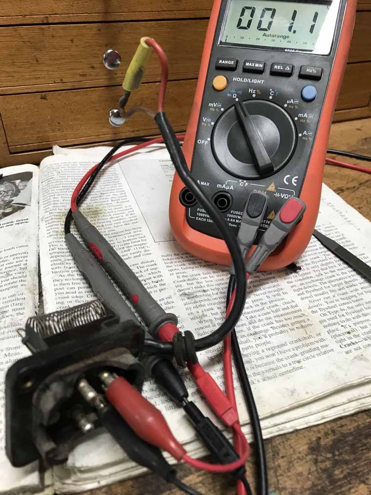 High speed (no resitor, and no bi-metallic switch for this one basically a direct short). 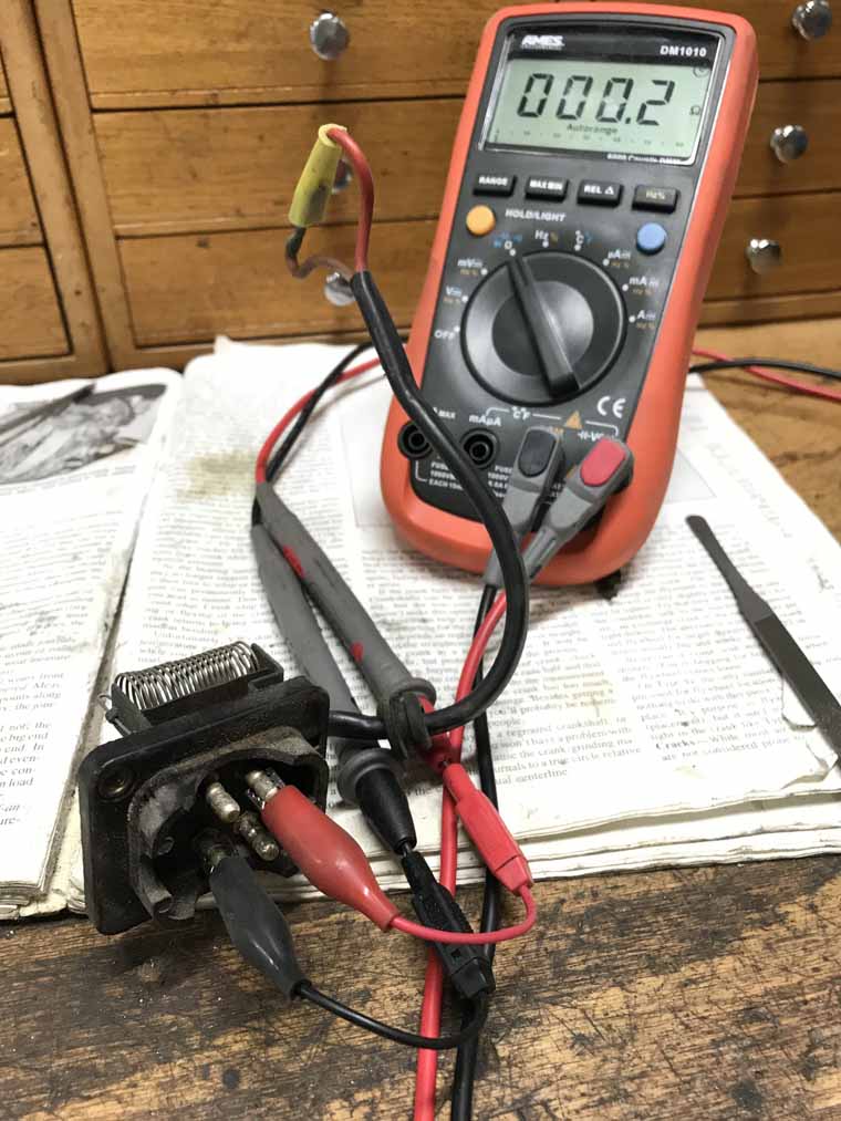 Finally here is a picture of the orientation of the resistor bank connector and keyway as I photographed it in the photos above. 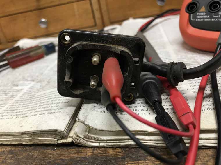 I also did measure the armature of my now defunct motor -- the armature of the motor measured in the range of 0.8 ohms to 1.2 ohms depending on where it was rotated to. So if you're measuring the resistor bank in the as installed postion, you would expect all values above to have 0.8 - 1.2 ohm added to them. This correlates pretty well to what I measured initially on my blower motor + resistor as an assembly.  |
|
|
|
Posts in this topic
DRPHIL914 Defrost fan rehab and rebuild thread (fresh air fan) Jan 21 2021, 08:55 AM Superhawk996 Not trying to be a jerk here. But I keep seeing a... Jan 21 2021, 09:43 AM
 DRPHIL914
Not trying to be a jerk here. But I keep seeing ... Jan 21 2021, 11:01 AM BeatNavy Phil, if it runs on one speed but not another (or ... Jan 21 2021, 11:41 AM DRPHIL914
Phil, if it runs on one speed but not another (or... Jan 21 2021, 12:05 PM mepstein Just like starter motors and alternator, the clima... Jan 21 2021, 12:08 PM framos914 I went through this a few months ago. Since I had ... Jan 21 2021, 12:18 PM Superhawk996 I'm here to help. Not trying to be a jerk. A... Jan 21 2021, 12:29 PM BeatNavy So I found the resistor pack. And I found my old ... Jan 21 2021, 12:30 PM Superhawk996 I'm also going to throw another one out there.... Jan 21 2021, 01:11 PM Superhawk996 page 72 post #1439
http://www.914world.com/bbs2... Jan 21 2021, 01:22 PM BeatNavy Ahhh...ok, that filled in at least some of the mis... Jan 21 2021, 01:50 PM Superhawk996
Amazing how complicated it is and how much engin... Jan 21 2021, 02:07 PM Superhawk996 Here's a few links about the 1/2 split method.... Jan 21 2021, 02:06 PM 914_teener Glad you guys are getting along.
I did this year... Jan 21 2021, 02:21 PM DRPHIL914
I'm here to help. Not trying to be a jerk. ... Jan 21 2021, 04:34 PM Superhawk996
I wonder if the spring in essence is your resist... Jan 21 2021, 05:01 PM DRPHIL914
I wonder if the spring in essence is your resis... Jan 21 2021, 08:33 PM bbrock @[url=http://www.914world.com/bbs2/index.php?showu... Jan 21 2021, 08:31 PM Superhawk996
As for repairing a blown resistor - how importan... Jan 22 2021, 06:56 AM bbrock
[quote name='bbrock' post='2884771' date='Jan 21 ... Jan 22 2021, 08:42 AM DRPHIL914
[quote name='bbrock' post='2884771' date='Jan 21... Jan 22 2021, 08:51 AM Mikey914 I'd look at a standard more "modern... Jan 22 2021, 08:49 AM Superhawk996 Not trying to be a kill joy on the DigiKey resisto... Jan 22 2021, 09:16 AM bbrock
Not trying to be a kill joy on the DigiKey resist... Jan 22 2021, 09:03 PM bdstone914
Not trying to be a kill joy on the DigiKey resis... Jan 23 2021, 12:18 AM bbrock
[quote name='bbrock' post='2884986' date='Jan 22 ... Jan 23 2021, 02:04 AM Superhawk996
I am a bit offended though. :evilgrin:
@bbr... Jan 24 2021, 12:18 PM Superhawk996 Well it turns out I will be posting a WTB.
My bl... Jan 24 2021, 12:35 PM DRPHIL914
Well it turns out I will be posting a WTB.
My b... Jan 24 2021, 07:03 PM Superhawk996 @DRPHIL914
" . . . so i guess new resistor ... Jan 25 2021, 06:42 AM DRPHIL914
[b]@[url=http://www.914world.com/bbs2/index.php?s... Jan 25 2021, 07:10 AM Superhawk996
. . . plan for tonight is to bench test wit the ... Jan 25 2021, 07:24 AM Superhawk996 @DRPHIL914
I'm going to pick one more snippe... Jan 25 2021, 07:38 AM DRPHIL914
[b]@[url=http://www.914world.com/bbs2/index.php?s... Jan 25 2021, 08:09 AM Superhawk996 @[url=http://www.914world.com/bbs2/index.php?showu... Jan 25 2021, 08:25 AM DRPHIL914 took the sucker apart and retested the resistor pa... Jan 25 2021, 06:14 PM bbrock
took the sucker apart and retested the resistor p... Jan 25 2021, 07:19 PM Superhawk996 @[url=http://www.914world.com/bbs2/index.php?showu... Jan 26 2021, 06:11 AM DRPHIL914
@[url=http://www.914world.com/bbs2/index.php?show... Jan 26 2021, 10:27 AM Superhawk996
. . . I will try and test the fan motor tonight... Jan 26 2021, 12:19 PM DRPHIL914 @Superhawk996
i went back and retested the resis... Jan 27 2021, 11:29 AM Superhawk996
how do you take the motor out of the white fan p... Jan 27 2021, 08:58 PM DRPHIL914
how do you take the motor out of the white fan ... Jan 27 2021, 11:40 PM Superhawk996 @DRPHIL914
Great job gutting that beast! Es... Jan 27 2021, 12:37 PM DRPHIL914
[b]@[url=http://www.914world.com/bbs2/index.php?s... Jan 27 2021, 01:17 PM DRPHIL914 i am going to get new leads, yes mine pulled apart... Jan 27 2021, 01:24 PM 914werke anyone order one of the new ones from URO or Por... Jan 27 2021, 01:27 PM Superhawk996 @Mikey914
I'll put in a 2nd vote for wish li... Jan 27 2021, 01:38 PM bbrock Hey Phil, if those pics show where you are measuri... Jan 27 2021, 02:34 PM Mikey914 Actually I've been working on a more complete ... Jan 27 2021, 06:16 PM DRPHIL914
Actually I've been working on a more complete... Jan 28 2021, 12:14 AM Superhawk996 @[url=http://www.914world.com/bbs2/index.php?showu... Jan 28 2021, 06:59 AM Superhawk996 I'll snap some photos of my resistor pack toni... Jan 28 2021, 07:12 AM Superhawk996 Warning: Carnage that can ensue trying to disasse... Jan 28 2021, 08:09 AM Mikey914 Can you post up some close up pics of the unservic... Jan 28 2021, 10:33 AM DRPHIL914
Warning: Carnage that can ensue trying to disass... Jan 28 2021, 10:58 AM Superhawk996 @Mikey914
Here is the motor frame.
The moto... Jan 28 2021, 07:31 PM Mikey914 Bosch has motors listed for these. If you have rem... Jan 28 2021, 08:12 PM Superhawk996
Bosch has motors listed for these. If you have re... Jan 28 2021, 08:41 PM DRPHIL914
Bosch has motors listed for these. If you have r... Jan 28 2021, 09:59 PM Mikey914 The only thing you could have a problem with the U... Jan 29 2021, 12:41 AM Superhawk996 For what it's worth good luck balancing one of... Jan 29 2021, 07:04 AM DRPHIL914
For what it's worth good luck balancing one o... Jan 29 2021, 12:16 PM UROpartsman The fan cage used in high quality URO Parts Blower... Feb 1 2021, 02:09 PM Superhawk996
The fan cage used in URO Parts Blower Motor assem... Feb 1 2021, 02:25 PM UROpartsman Would you be so kind as to weight a unit? I just ... Feb 1 2021, 07:04 PM Superhawk996
No problem, the one in our photo weighs 556g / 1... Feb 1 2021, 07:33 PM DRPHIL914
[quote name='UROpartsman' post='2887530' date='Fe... Feb 3 2021, 07:29 PM DRPHIL914 @UROpartsman
[b]@[url=http://www.914world.com/bb... Feb 1 2021, 02:38 PM Superhawk996 This is what I was calling the blower housing fram... Feb 4 2021, 09:38 AM DRPHIL914
The fan cage used in URO Parts Blower Motor assem... Feb 5 2021, 09:26 AM UROpartsman Awesome Phil, keep us updated! Feb 5 2021, 10:57 AM DRPHIL914 @Mikey914
[b]@[url=http://www.914world.com/bbs2/... Feb 8 2021, 09:00 AM Superhawk996
[b]@[url=http://www.914world.com/bbs2/index.php?s... Feb 8 2021, 09:29 AM DRPHIL914
[b]@[url=http://www.914world.com/bbs2/index.php?... Feb 8 2021, 10:19 AM Mikey914
[b]@[url=http://www.914world.com/bbs2/index.php?s... Feb 8 2021, 05:10 PM Superhawk996
[b]@[url=http://www.914world.com/bbs2/index.php?... Feb 8 2021, 05:15 PM Superhawk996 @Mikey914
I have received a seal kit but wasn... Feb 8 2021, 09:18 AM Mikey914 Go ahead and post up some pics. I will also be inc... Feb 8 2021, 05:21 PM DRPHIL914 @Mikey914
[b]@[url=http://www.914world.com/bbs2/... Feb 13 2021, 02:38 PM Superhawk996 @Mikey914
:drooley:
You're killing me.
... Feb 14 2021, 11:29 AM DRPHIL914
[b]@[url=http://www.914world.com/bbs2/index.php?s... Feb 14 2021, 11:50 AM DRPHIL914 i’ve had this apart for some time and finally ha... Feb 14 2021, 09:51 PM DRPHIL914 after polishing , overkill i know but might as wel... Feb 14 2021, 10:03 PM DRPHIL914 UPDATE:
finally got around to installing this ne... Mar 23 2021, 08:19 AM DRPHIL914 tank up and box accessed- pretty clean under there... Mar 23 2021, 08:24 AM bob164 Don't think this is the issue with the fans, b... Mar 23 2021, 02:39 PM DRPHIL914
Don't think this is the issue with the fans, ... Mar 24 2021, 04:59 AM bob164 The picture isn't that clear, was referring to... Mar 24 2021, 11:22 AM DRPHIL914
The picture isn't that clear, was referring t... Mar 25 2021, 06:39 AM DRPHIL914 ok update from trouble shooting last night,
after... Mar 25 2021, 06:52 AM Rob-O Quick question and I don’t have a schematic in f... Mar 25 2021, 07:27 AM DRPHIL914
Quick question and I don’t have a schematic in ... Mar 25 2021, 10:22 AM DRPHIL914 OK finally last night i was able to sort thru the ... Mar 26 2021, 08:25 AM DRPHIL914 this is how the wiring should be connected.
i am ... Mar 26 2021, 08:35 AM Mikey914 Doing some research. Looks like we can form these ... Mar 26 2021, 02:42 PM Bullethead A huge thank you to all the contributors of this t... May 11 2023, 06:46 AM
DRPHIL914
Not trying to be a jerk here. But I keep seeing ... Jan 21 2021, 11:01 AM BeatNavy Phil, if it runs on one speed but not another (or ... Jan 21 2021, 11:41 AM DRPHIL914
Phil, if it runs on one speed but not another (or... Jan 21 2021, 12:05 PM mepstein Just like starter motors and alternator, the clima... Jan 21 2021, 12:08 PM framos914 I went through this a few months ago. Since I had ... Jan 21 2021, 12:18 PM Superhawk996 I'm here to help. Not trying to be a jerk. A... Jan 21 2021, 12:29 PM BeatNavy So I found the resistor pack. And I found my old ... Jan 21 2021, 12:30 PM Superhawk996 I'm also going to throw another one out there.... Jan 21 2021, 01:11 PM Superhawk996 page 72 post #1439
http://www.914world.com/bbs2... Jan 21 2021, 01:22 PM BeatNavy Ahhh...ok, that filled in at least some of the mis... Jan 21 2021, 01:50 PM Superhawk996
Amazing how complicated it is and how much engin... Jan 21 2021, 02:07 PM Superhawk996 Here's a few links about the 1/2 split method.... Jan 21 2021, 02:06 PM 914_teener Glad you guys are getting along.
I did this year... Jan 21 2021, 02:21 PM DRPHIL914
I'm here to help. Not trying to be a jerk. ... Jan 21 2021, 04:34 PM Superhawk996
I wonder if the spring in essence is your resist... Jan 21 2021, 05:01 PM DRPHIL914
I wonder if the spring in essence is your resis... Jan 21 2021, 08:33 PM bbrock @[url=http://www.914world.com/bbs2/index.php?showu... Jan 21 2021, 08:31 PM Superhawk996
As for repairing a blown resistor - how importan... Jan 22 2021, 06:56 AM bbrock
[quote name='bbrock' post='2884771' date='Jan 21 ... Jan 22 2021, 08:42 AM DRPHIL914
[quote name='bbrock' post='2884771' date='Jan 21... Jan 22 2021, 08:51 AM Mikey914 I'd look at a standard more "modern... Jan 22 2021, 08:49 AM Superhawk996 Not trying to be a kill joy on the DigiKey resisto... Jan 22 2021, 09:16 AM bbrock
Not trying to be a kill joy on the DigiKey resist... Jan 22 2021, 09:03 PM bdstone914
Not trying to be a kill joy on the DigiKey resis... Jan 23 2021, 12:18 AM bbrock
[quote name='bbrock' post='2884986' date='Jan 22 ... Jan 23 2021, 02:04 AM Superhawk996
I am a bit offended though. :evilgrin:
@bbr... Jan 24 2021, 12:18 PM Superhawk996 Well it turns out I will be posting a WTB.
My bl... Jan 24 2021, 12:35 PM DRPHIL914
Well it turns out I will be posting a WTB.
My b... Jan 24 2021, 07:03 PM Superhawk996 @DRPHIL914
" . . . so i guess new resistor ... Jan 25 2021, 06:42 AM DRPHIL914
[b]@[url=http://www.914world.com/bbs2/index.php?s... Jan 25 2021, 07:10 AM Superhawk996
. . . plan for tonight is to bench test wit the ... Jan 25 2021, 07:24 AM Superhawk996 @DRPHIL914
I'm going to pick one more snippe... Jan 25 2021, 07:38 AM DRPHIL914
[b]@[url=http://www.914world.com/bbs2/index.php?s... Jan 25 2021, 08:09 AM Superhawk996 @[url=http://www.914world.com/bbs2/index.php?showu... Jan 25 2021, 08:25 AM DRPHIL914 took the sucker apart and retested the resistor pa... Jan 25 2021, 06:14 PM bbrock
took the sucker apart and retested the resistor p... Jan 25 2021, 07:19 PM Superhawk996 @[url=http://www.914world.com/bbs2/index.php?showu... Jan 26 2021, 06:11 AM DRPHIL914
@[url=http://www.914world.com/bbs2/index.php?show... Jan 26 2021, 10:27 AM Superhawk996
. . . I will try and test the fan motor tonight... Jan 26 2021, 12:19 PM DRPHIL914 @Superhawk996
i went back and retested the resis... Jan 27 2021, 11:29 AM Superhawk996
how do you take the motor out of the white fan p... Jan 27 2021, 08:58 PM DRPHIL914
how do you take the motor out of the white fan ... Jan 27 2021, 11:40 PM Superhawk996 @DRPHIL914
Great job gutting that beast! Es... Jan 27 2021, 12:37 PM DRPHIL914
[b]@[url=http://www.914world.com/bbs2/index.php?s... Jan 27 2021, 01:17 PM DRPHIL914 i am going to get new leads, yes mine pulled apart... Jan 27 2021, 01:24 PM 914werke anyone order one of the new ones from URO or Por... Jan 27 2021, 01:27 PM Superhawk996 @Mikey914
I'll put in a 2nd vote for wish li... Jan 27 2021, 01:38 PM bbrock Hey Phil, if those pics show where you are measuri... Jan 27 2021, 02:34 PM Mikey914 Actually I've been working on a more complete ... Jan 27 2021, 06:16 PM DRPHIL914
Actually I've been working on a more complete... Jan 28 2021, 12:14 AM Superhawk996 @[url=http://www.914world.com/bbs2/index.php?showu... Jan 28 2021, 06:59 AM Superhawk996 I'll snap some photos of my resistor pack toni... Jan 28 2021, 07:12 AM Superhawk996 Warning: Carnage that can ensue trying to disasse... Jan 28 2021, 08:09 AM Mikey914 Can you post up some close up pics of the unservic... Jan 28 2021, 10:33 AM DRPHIL914
Warning: Carnage that can ensue trying to disass... Jan 28 2021, 10:58 AM Superhawk996 @Mikey914
Here is the motor frame.
The moto... Jan 28 2021, 07:31 PM Mikey914 Bosch has motors listed for these. If you have rem... Jan 28 2021, 08:12 PM Superhawk996
Bosch has motors listed for these. If you have re... Jan 28 2021, 08:41 PM DRPHIL914
Bosch has motors listed for these. If you have r... Jan 28 2021, 09:59 PM Mikey914 The only thing you could have a problem with the U... Jan 29 2021, 12:41 AM Superhawk996 For what it's worth good luck balancing one of... Jan 29 2021, 07:04 AM DRPHIL914
For what it's worth good luck balancing one o... Jan 29 2021, 12:16 PM UROpartsman The fan cage used in high quality URO Parts Blower... Feb 1 2021, 02:09 PM Superhawk996
The fan cage used in URO Parts Blower Motor assem... Feb 1 2021, 02:25 PM UROpartsman Would you be so kind as to weight a unit? I just ... Feb 1 2021, 07:04 PM Superhawk996
No problem, the one in our photo weighs 556g / 1... Feb 1 2021, 07:33 PM DRPHIL914
[quote name='UROpartsman' post='2887530' date='Fe... Feb 3 2021, 07:29 PM DRPHIL914 @UROpartsman
[b]@[url=http://www.914world.com/bb... Feb 1 2021, 02:38 PM Superhawk996 This is what I was calling the blower housing fram... Feb 4 2021, 09:38 AM DRPHIL914
The fan cage used in URO Parts Blower Motor assem... Feb 5 2021, 09:26 AM UROpartsman Awesome Phil, keep us updated! Feb 5 2021, 10:57 AM DRPHIL914 @Mikey914
[b]@[url=http://www.914world.com/bbs2/... Feb 8 2021, 09:00 AM Superhawk996
[b]@[url=http://www.914world.com/bbs2/index.php?s... Feb 8 2021, 09:29 AM DRPHIL914
[b]@[url=http://www.914world.com/bbs2/index.php?... Feb 8 2021, 10:19 AM Mikey914
[b]@[url=http://www.914world.com/bbs2/index.php?s... Feb 8 2021, 05:10 PM Superhawk996
[b]@[url=http://www.914world.com/bbs2/index.php?... Feb 8 2021, 05:15 PM Superhawk996 @Mikey914
I have received a seal kit but wasn... Feb 8 2021, 09:18 AM Mikey914 Go ahead and post up some pics. I will also be inc... Feb 8 2021, 05:21 PM DRPHIL914 @Mikey914
[b]@[url=http://www.914world.com/bbs2/... Feb 13 2021, 02:38 PM Superhawk996 @Mikey914
:drooley:
You're killing me.
... Feb 14 2021, 11:29 AM DRPHIL914
[b]@[url=http://www.914world.com/bbs2/index.php?s... Feb 14 2021, 11:50 AM DRPHIL914 i’ve had this apart for some time and finally ha... Feb 14 2021, 09:51 PM DRPHIL914 after polishing , overkill i know but might as wel... Feb 14 2021, 10:03 PM DRPHIL914 UPDATE:
finally got around to installing this ne... Mar 23 2021, 08:19 AM DRPHIL914 tank up and box accessed- pretty clean under there... Mar 23 2021, 08:24 AM bob164 Don't think this is the issue with the fans, b... Mar 23 2021, 02:39 PM DRPHIL914
Don't think this is the issue with the fans, ... Mar 24 2021, 04:59 AM bob164 The picture isn't that clear, was referring to... Mar 24 2021, 11:22 AM DRPHIL914
The picture isn't that clear, was referring t... Mar 25 2021, 06:39 AM DRPHIL914 ok update from trouble shooting last night,
after... Mar 25 2021, 06:52 AM Rob-O Quick question and I don’t have a schematic in f... Mar 25 2021, 07:27 AM DRPHIL914
Quick question and I don’t have a schematic in ... Mar 25 2021, 10:22 AM DRPHIL914 OK finally last night i was able to sort thru the ... Mar 26 2021, 08:25 AM DRPHIL914 this is how the wiring should be connected.
i am ... Mar 26 2021, 08:35 AM Mikey914 Doing some research. Looks like we can form these ... Mar 26 2021, 02:42 PM Bullethead A huge thank you to all the contributors of this t... May 11 2023, 06:46 AM |
6 User(s) are reading this topic (6 Guests and 0 Anonymous Users)
0 Members:

|
Lo-Fi Version | Time is now: 27th September 2024 - 12:19 PM |
Invision Power Board
v9.1.4 © 2024 IPS, Inc.