|
|
|
Porsche, and the Porsche crest are registered trademarks of Dr. Ing. h.c. F. Porsche AG.
This site is not affiliated with Porsche in any way. Its only purpose is to provide an online forum for car enthusiasts. All other trademarks are property of their respective owners. |
|
|


| anderssj |
 Mar 21 2022, 01:00 PM Mar 21 2022, 01:00 PM
Post
#1
|
|
Dog is my copilot...  Group: Members Posts: 1,689 Joined: 28-January 03 From: VA Member No.: 207 Region Association: MidAtlantic Region |
I'm finally getting around to "safetyizing" the three unfused/hot wires at the battery on my 914.
First, a disclaimer: this is on a 1972 car. I think power distribution on earlier cars is similar--but I know there are major wiring changes to the later cars. Always check the appropriate wiring diagrams for your car before any starting work. Disconnecting battery "-"/"ground" is a good idea too. The wires I'm working with are shown here: 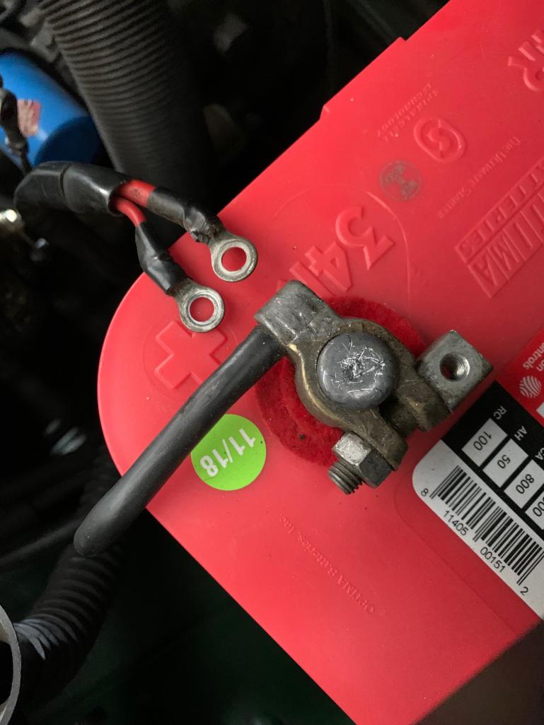 There are two smaller red wires crimped into the single ring terminal on the left, and a larger single wire/ring terminal on the right. As designed, all three are hot and unfused. (IMG:style_emoticons/default/dry.gif) If I'm reading the wiring diagrams correctly, the two smaller wires go to terminals 12 and 14 on the regulator plate and provide power to heater fan, fuel pump, rear window defogger, etc. Not sure of the total load/power on this circuit... The larger wire on the right goes forward to the power distribution/junction near the fuse box (it's the bake-lite block shown in this picture [ripped off from advman89's earlier thread]): 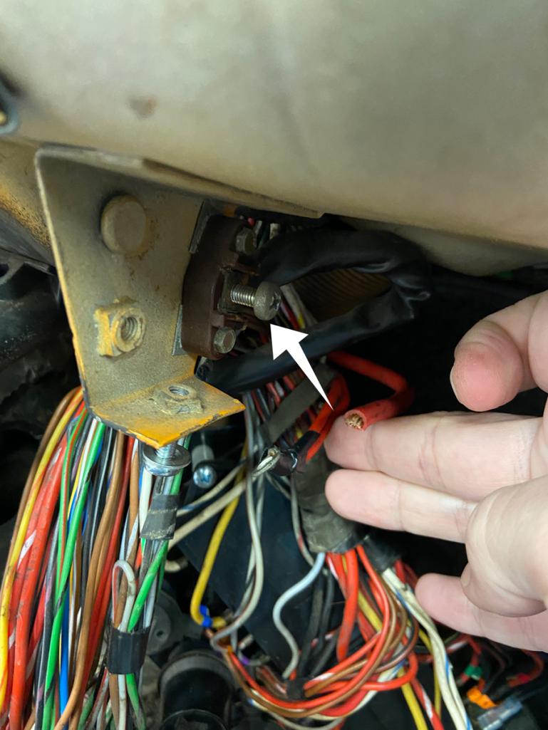 I think the power distribution/junction is the tiny "32" circled in this diagram: 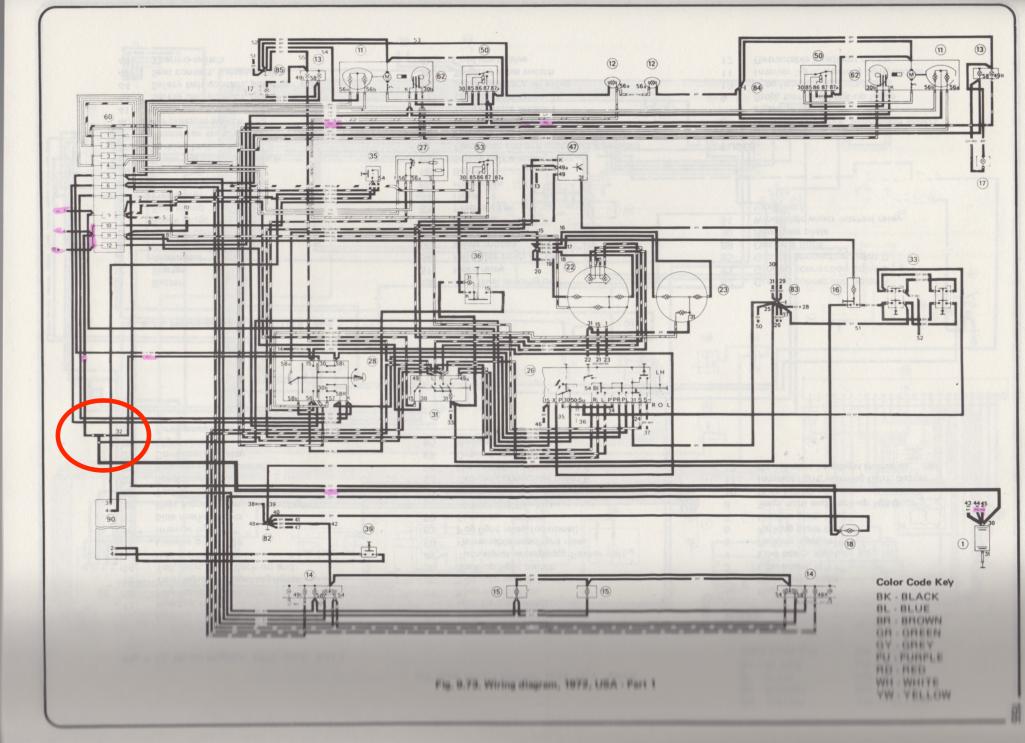 From the power distribution/junction, electrical power is distributed through additional unfused/hot wires to the column/ignition switch("26"), headlight switch ("28"), fuses 10, 11, and 12, and other components. Not sure of the total load on this circuit either... As others here have done, I'm planning to install a supplemental fuse box between the battery "+" and these three wires to give myself additional margin of safety/peace of mind... The box I'm planning to use is a Volvo part with a 8ga cable from the battery "+" to a common bus. The box can support a total of four circuits (I'm only going to use two, one for each ring terminal). The box currently has 40 amp fuses. 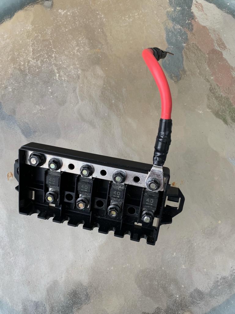 I don't think any drilling or cutting will be needed, so I will be able to put the car back into original configuration in a few minutes. Does anyone know the total load on these circuits? Given that alternator output is only 50 amps, I figure that new 40 amp replacement fuses for the ones shown in the box should be fine...but thought I should ask the folks here. Thanks in advance for any advice, insights, and BTDTs! (IMG:style_emoticons/default/pray.gif) |
   |

 
|
  |
Replies
| lesorubcheek |
Mar 21 2022, 04:49 PM
Post
#2
|
|
Member Group: Members Posts: 193 Joined: 21-April 21 From: Florida Member No.: 25,463 Region Association: South East States |
Sounds like a great idea, but just a little hesitation when I think of the quote that seems to pop up around here numerous times; "If Porsche didn't do it, then there was probably a good reason since those German engineers are more intelligent than the rest of us normal humans". OK, maybe not verbatim, but still maybe dig a bit to see if there may be any drawbacks, and no offense intended to any German engineers or anyone else.
Earlier in life, I'd have tried to measure resistive loads for all the components and come up with a max expected current draw, but now, a clamp on current meter seems to make a lot more sense. Maybe try to energize everything on the circuits in question, or as much as possible anyway, and see how much current is actually being drawn. Clamp ons are fairly cheap. Definitely want to look for peaks since you don't want fuses blowing all the time. Again, it sounds like a great idea and I'm interested in seeing how you implement it. Dan |
|
|
|
| Superhawk996 |
Mar 21 2022, 05:25 PM
Post
#3
|
|
914 Guru Group: Members Posts: 6,469 Joined: 25-August 18 From: Woods of N. Idaho Member No.: 22,428 Region Association: Galt's Gulch |
QUOTE(lesorubcheek @ Mar 21 2022, 06:49 PM)  Earlier in life, I'd have tried to measure resistive loads for all the components and come up with a max expected current draw, but now, a clamp on current meter seems to make a lot more sense. Dan (IMG:style_emoticons/default/aktion035.gif) Sure do it the easy way! (IMG:style_emoticons/default/av-943.gif) |
 |
|
| lesorubcheek |
Mar 21 2022, 05:57 PM
Post
#4
|
|
Member Group: Members Posts: 193 Joined: 21-April 21 From: Florida Member No.: 25,463 Region Association: South East States |
QUOTE(Superhawk996 @ Mar 21 2022, 06:25 PM) QUOTE(lesorubcheek @ Mar 21 2022, 06:49 PM) Earlier in life, I'd have tried to measure resistive loads for all the components and come up with a max expected current draw, but now, a clamp on current meter seems to make a lot more sense. Dan (IMG:style_emoticons/default/aktion035.gif) Sure do it the easy way! (IMG:style_emoticons/default/av-943.gif) Hey, it's laziness, not wisdom. (IMG:style_emoticons/default/biggrin.gif) Dan |
|
|
|
Posts in this topic
 anderssj supplemental fuse box Mar 21 2022, 01:00 PM
 Superhawk996
Does anyone know the total load on these circuit... Mar 21 2022, 04:24 PM
Superhawk996
Does anyone know the total load on these circuit... Mar 21 2022, 04:24 PM mepstein
Sounds like a great idea, but just a little hesit... Mar 21 2022, 08:29 PM
mepstein
Sounds like a great idea, but just a little hesit... Mar 21 2022, 08:29 PM vitamin914
Sounds like a great idea, but just a little hesi... Mar 22 2022, 07:09 AM dhuckabay Curious. Does a clamp on amp meter work on DC. I... Mar 21 2022, 10:12 PM vitamin914 Not every clamp meter can measure DC current. All... Mar 22 2022, 06:49 AM lesorubcheek
Curious. Does a clamp on amp meter work on DC. ... Mar 22 2022, 06:49 AM 914Mels
I'm finally getting around to "safetyizi... Mar 21 2022, 05:04 PM 914Mels Rather than go through all the trouble of mounting... Mar 21 2022, 05:08 PM Costa05 I have a 73 that had four unfused circuits diectly... Mar 21 2022, 09:15 PM 914werke Everything old is new again
http://www.914world.c... Mar 21 2022, 10:52 PM advman89 That grounding block was removed...wires were then... Mar 22 2022, 07:31 AM barefoot I've done the same thing as my original harnes... Mar 23 2022, 06:15 AM anderssj Thanks for all of the replies—lots to think abou... Mar 23 2022, 09:34 PM
vitamin914
Sounds like a great idea, but just a little hesi... Mar 22 2022, 07:09 AM dhuckabay Curious. Does a clamp on amp meter work on DC. I... Mar 21 2022, 10:12 PM vitamin914 Not every clamp meter can measure DC current. All... Mar 22 2022, 06:49 AM lesorubcheek
Curious. Does a clamp on amp meter work on DC. ... Mar 22 2022, 06:49 AM 914Mels
I'm finally getting around to "safetyizi... Mar 21 2022, 05:04 PM 914Mels Rather than go through all the trouble of mounting... Mar 21 2022, 05:08 PM Costa05 I have a 73 that had four unfused circuits diectly... Mar 21 2022, 09:15 PM 914werke Everything old is new again
http://www.914world.c... Mar 21 2022, 10:52 PM advman89 That grounding block was removed...wires were then... Mar 22 2022, 07:31 AM barefoot I've done the same thing as my original harnes... Mar 23 2022, 06:15 AM anderssj Thanks for all of the replies—lots to think abou... Mar 23 2022, 09:34 PM |
1 User(s) are reading this topic (1 Guests and 0 Anonymous Users)
0 Members:

|
Lo-Fi Version | Time is now: 27th September 2024 - 10:25 AM |
Invision Power Board
v9.1.4 © 2024 IPS, Inc.