|
|
|
Porsche, and the Porsche crest are registered trademarks of Dr. Ing. h.c. F. Porsche AG.
This site is not affiliated with Porsche in any way. Its only purpose is to provide an online forum for car enthusiasts. All other trademarks are property of their respective owners. |
|
|


| dbledsoe |
 Jul 5 2005, 11:03 AM Jul 5 2005, 11:03 AM
Post
#1
|
|
Mutineer  Group: Members Posts: 300 Joined: 13-May 03 From: Boise, ID. Member No.: 687 |
Got the engine & transaxle into the car, bolted up at the back, and ready to fabricate a few minor parts to make the new forward crossmember mate to the body. The forward crossmember was bought from Speedway Motors in Lincoln Nebraska for a grand total of $58 to my door (http://www.speedwaymotors.com/). The crossmember clears the shift linkage just fine. (IMG:http://www.914world.com/bbs2/html/emoticons/mueba.gif)
Attached thumbnail(s) 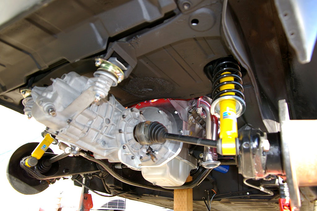
|
   |

 
|
  |
Replies
| dbledsoe |
Oct 4 2005, 01:43 PM
Post
#2
|
||||
|
Mutineer Group: Members Posts: 300 Joined: 13-May 03 From: Boise, ID. Member No.: 687 |
Hello Phillip, The expansion tank has three lines to/from it. The upper line from the tank body goes to the intake manifold water passage near the thremostat housing. The lower line from the tank body runs to the inlet side of the water pump. The highest line (clear plastic) is the overflow line and it runs to the plastic overflow tank you see in the photos. The engine mount crossmember bolts to the same place as the original Porsche engine mount crossmember except that it bolts to the frame from the top side rather than the bottom side. The phot below shows what it looks like out of the car but that is the exact smae position it will have installed. The welded feet you see in the photo replace the original plate that the original engine mount crossmember bolted to. The two ends of the crossmember telescope to facilitate installation into the chassis and are then pulled out to mate to the engine mounting points on the chassis. The feet of my crossmemebr are drilled and threaded to accept two 3/8" bolts on each side. Once the crossmemeber is in place the bolts are run up from beneath the care and tightened down. Once that is complete I then drilled a pair of 1/4" holes through each end of the crossmemeber and into and through the 1 1/2" bars on the ends. I put a pair of quick 1/4" release pins in each of those holes to keep the crossmember from sliding side to side or rotating on axis. I hope that makes sense. I'll try to get a better picture of how the mount bolts to the chassis tonight and post it tomorrow. Don Attached thumbnail(s) 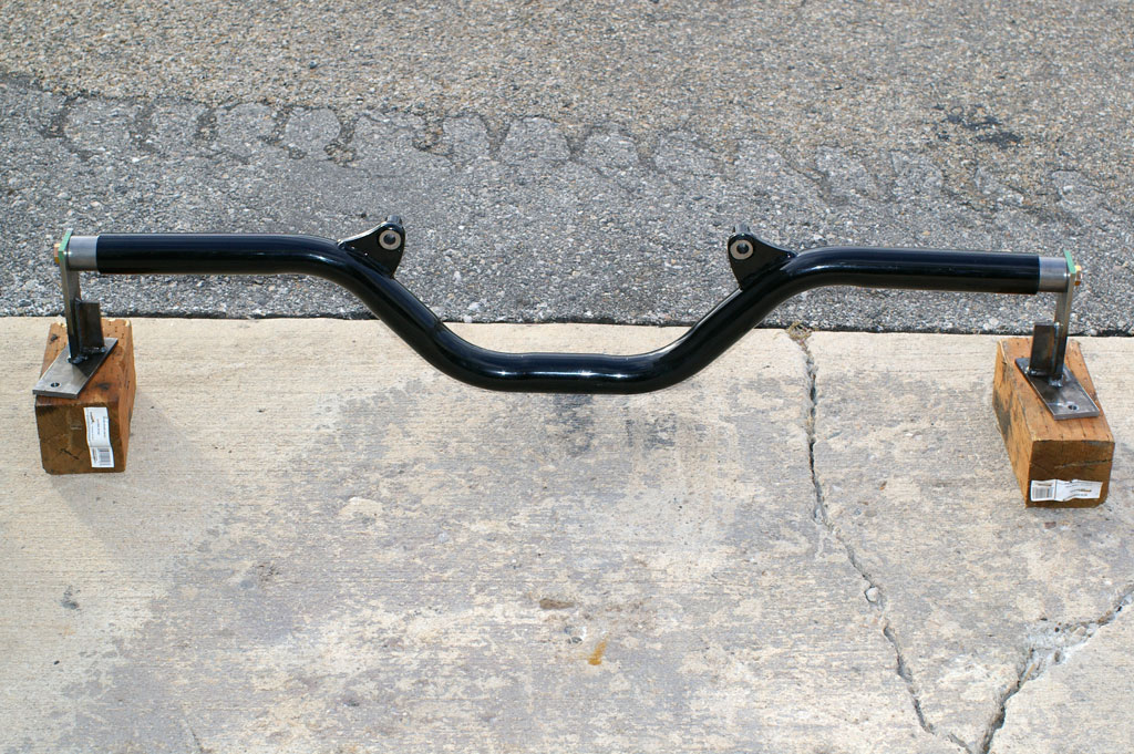
|
||||
|
|
|
||||
Posts in this topic
 dbledsoe Update Buick V6 in 914 Jul 5 2005, 11:03 AM
 dbledsoe And another Jul 5 2005, 11:05 AM dbledsoe And another Jul 5 2005, 11:06 AM bondo NICE!!! And I don't think I have E... Jul 5 2005, 11:06 AM 914GT Looks sweet! Great job! Jul 5 2005, 11:08 AM dbledsoe And another Jul 5 2005, 11:08 AM ClayPerrine That is one funny looking carburetor!! Jul 5 2005, 11:10 AM Rotary'14 Looks like a clean install! Congrats on a gre... Jul 5 2005, 11:12 AM 914GT Have you figured out how you'll make the bend ... Jul 5 2005, 11:12 AM dbledsoe Jul 5 2005, 11:12 AM neo914-6 http://www.914world.com/bbs2/ht... Jul 5 2005, 11:15 AM dbledsoe Jul 5 2005, 11:16 AM dbledsoe
