|
|
|
Porsche, and the Porsche crest are registered trademarks of Dr. Ing. h.c. F. Porsche AG.
This site is not affiliated with Porsche in any way. Its only purpose is to provide an online forum for car enthusiasts. All other trademarks are property of their respective owners. |
|
|

  |

| skeates |
 Oct 23 2014, 01:36 PM Oct 23 2014, 01:36 PM
Post
#1
|
|
Member  Group: Members Posts: 218 Joined: 28-February 05 From: Sacramento, ca Member No.: 3,684 Region Association: Northern California |
Hi All - I've been looking into different solutions for merging the two coolant outputs on the 6-cylinder suby motors into a single tube. I finally found something that should work pretty well with these guys Jags That Run. The idea is to use a "T" to merge the two 1-1/8" outlets into a single 1-1/4" hose. The fitting would also be tapped for a 1/4" nipple which would be used as a steam line and routed back to a surge/expansion tank. The following pictures show a rough diagram of my expected set-up and then some examples of their "T" fittings. (Note that I didn't bother including any of the return lines in the diagram)
I'm posting this to see if anyone else would be interested in this fitting since right now it's a one-off production. If I just purchase the one it will be ~$80. However; if I can get 10 or more orders the price will come down to about $30/each! So...any interests? 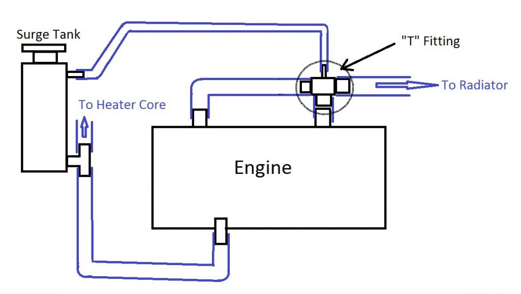 (IMG:http://www.914world.com/bbs2/uploads_offsite/www.jagsthatrun.com-3684-1414093000.1.jpg) |
   |

 
|
| 76-914 |
Oct 23 2014, 04:34 PM
Post
#2
|
|
Repeat Offender & Resident Subaru Antagonist Group: Members Posts: 13,485 Joined: 23-January 09 From: Temecula, CA Member No.: 9,964 Region Association: Southern California |
FWIW, your right bank will run cooler than the left because there will be less resistance on that side. Why? Less distance. The tee should be centered between the outlets. IOW, if the left side has one 90 and 15" developed run to the T the right side should be identical. Not saying it won't work, just expect the temps to differ between the L&R banks.
|
 |
|
| Mike Bellis |
Oct 23 2014, 08:11 PM
Post
#3
|
|
Resident Electrician Group: Members Posts: 8,345 Joined: 22-June 09 From: Midlothian TX Member No.: 10,496 Region Association: None |
QUOTE(76-914 @ Oct 23 2014, 03:34 PM)  FWIW, your right bank will run cooler than the left because there will be less resistance on that side. Why? Less distance. The tee should be centered between the outlets. IOW, if the left side has one 90 and 15" developed run to the T the right side should be identical. Not saying it won't work, just expect the temps to differ between the L&R banks. Maybe not. The laminar flow from the Left is straight through and should flow better, ergo be cooler. I agree the T should be in the center. (IMG:style_emoticons/default/smile.gif) |
|
|
|
| skeates |
Oct 23 2014, 10:20 PM
Post
#4
|
|
Member Group: Members Posts: 218 Joined: 28-February 05 From: Sacramento, ca Member No.: 3,684 Region Association: Northern California |
Good thoughts! My reasoning behind locating the "T" there was somewhat in line with Mike's logic. The flow from the left side would be at a lower pressure at the T (due to the pressure drops in the line from it's outlet to the T) than the flow exiting the right side of the engine. This should help the two streams merge in the less than ideal T fitting. While I don't imagine the two sides will flow exactly the same I'm not worried about the differences. In reality the length of hose coming from the left will be less than 1 foot, so the pressure drop shouldn't be all that much. I actually disagree with placing it in the middle as that would cause the two flows to crash into each other while at the same time forcing them to change directions in a sharp 90 degree bend. Seems to me that would cause significantly more turbulence and a much larger pressure drop to impede flow for both sides of the engine. Without modeling it or experimenting with it though I imagine that this is all speculation at this point. I added the steam right on-top of the T in order to help get rid of any flashed coolant resulting from the sharp transition. Of course, the ideal solution would be to find someone to tig up a "y" pipe which could merge the two streams more efficiently....any volunteers? :-)
Regarding the "T", if folks would prefer to have the T designed to allow the two outlets to merge in the middle I can inquire if that would require another run of 10 or if some of the CNC programming for one configuration would help reduce prices for the other. |
|
|
|
| Chris914n6 |
Oct 23 2014, 11:11 PM
Post
#5
|
|
Jackstands are my life. Group: Members Posts: 3,302 Joined: 14-March 03 From: Las Vegas, NV Member No.: 431 Region Association: Southwest Region |
Every modern v6 I've worked on has water leaving the engine like the pic. I doubt it's an issue.
|
|
|
|
| mgp4591 |
Oct 24 2014, 12:12 AM
Post
#6
|
|
914 Guru Group: Members Posts: 5,363 Joined: 1-August 12 From: Salt Lake City Ut Member No.: 14,748 Region Association: Intermountain Region |
QUOTE(Chris914n6 @ Oct 23 2014, 11:11 PM) Every modern v6 I've worked on has water leaving the engine like the pic. I doubt it's an issue. Not sure, but maybe because it's a V6 instead of a flat 6? When it all gets sorted, I'd be up for one... And is it for all 6s or just certain models? |
|
|
|
| 76-914 |
Oct 24 2014, 08:39 AM
Post
#7
|
|
Repeat Offender & Resident Subaru Antagonist Group: Members Posts: 13,485 Joined: 23-January 09 From: Temecula, CA Member No.: 9,964 Region Association: Southern California |
It would be interesting to have some real world numbers on this. An IR thermometer will show differences. I'll post my #'s in the next few day's here. Commercial water heaters are combined in the manner I described above. Always. It's critical in this case if you want them to "all" share the work load equally. I didn't conjure this up. That being said, I would bet that the slight casting differences in the heads will be more of an influence than the piping itself!
|
|
|
|
| skeates |
Oct 24 2014, 09:26 AM
Post
#8
|
|
Member Group: Members Posts: 218 Joined: 28-February 05 From: Sacramento, ca Member No.: 3,684 Region Association: Northern California |
QUOTE(mgp4591 @ Oct 23 2014, 11:12 PM) QUOTE(Chris914n6 @ Oct 23 2014, 11:11 PM) Every modern v6 I've worked on has water leaving the engine like the pic. I doubt it's an issue. Not sure, but maybe because it's a V6 instead of a flat 6? When it all gets sorted, I'd be up for one... And is it for all 6s or just certain models? Awesome! This would be for all of the EZ series Subaru flat 6 motors (EZ30 & EZ36). This would not be needed for the EG33 (SVX motors) since they have a single output for the coolant exiting the motor. |
|
|
|
|
1 User(s) are reading this topic (1 Guests and 0 Anonymous Users)
0 Members:

|
Lo-Fi Version | Time is now: 19th April 2024 - 03:13 PM |
Invision Power Board
v9.1.4 © 2024 IPS, Inc.