|
|
|
Porsche, and the Porsche crest are registered trademarks of Dr. Ing. h.c. F. Porsche AG.
This site is not affiliated with Porsche in any way. Its only purpose is to provide an online forum for car enthusiasts. All other trademarks are property of their respective owners. |
|
|

  |

| JFG |
 Jan 24 2017, 08:11 AM Jan 24 2017, 08:11 AM
Post
#1
|
|
Senior Member  Group: Members Posts: 686 Joined: 7-April 16 From: Wales Member No.: 19,869 Region Association: None |
As my car came part stripped and incomplete the put back together process is throwing up allsorts.
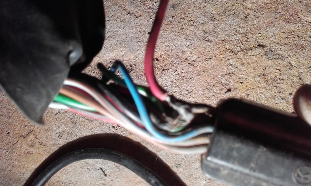
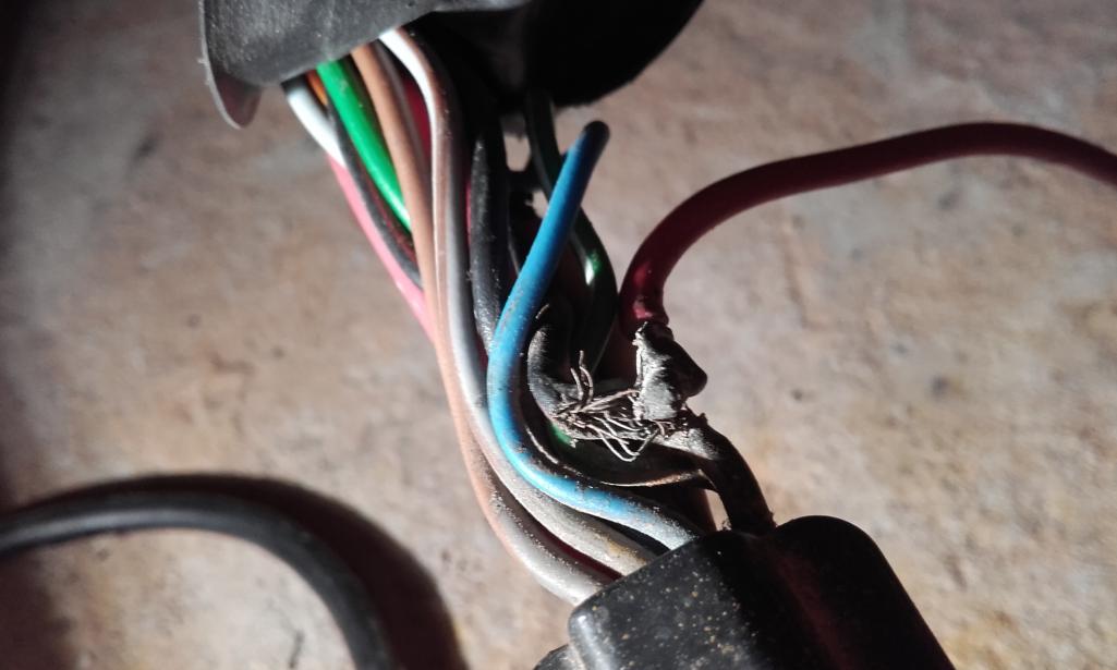
I bought a relay board from camp 914 and then discovered a previous owner had chopped the fixing brackets out. I made new ones and fitted them today. When connecting the largest loom connector i found a wire had been spliced and another part soldered to it. The wire cut is the black with red stripe. I can't read wiring diagrams but i have found numerous postings on the web about jumpers needed for the fuel pump usually. Can someone tell me what the black/red wire is for? When i get to fit and start the engine in the future i can then see what the board is like. |
   |

 
|
| JFG |
Jan 24 2017, 10:39 AM
Post
#2
|
|
Senior Member Group: Members Posts: 686 Joined: 7-April 16 From: Wales Member No.: 19,869 Region Association: None |
  |
|
|
|
| porschetub |
Jan 24 2017, 12:23 PM
Post
#3
|
|
Advanced Member Group: Members Posts: 4,697 Joined: 25-July 15 From: New Zealand Member No.: 18,995 Region Association: None |
I'am presuming that's the 14pin connector,this wire is pin #13 which is the fuel pump,where is that wire going ? most likely a jumper wire,be aware this could be unfused or bypassing the relay.....not good practice.
Go to the tech section on here to find out,also visit Bowlsby.net tech section for further info,very helpful resource . |
|
|
|
| JFG |
Jan 24 2017, 04:55 PM
Post
#4
|
|
Senior Member Group: Members Posts: 686 Joined: 7-April 16 From: Wales Member No.: 19,869 Region Association: None |
Thanks for the advice.
I can actually understand those diagrams fairly well. (IMG:style_emoticons/default/beerchug.gif) |
|
|
|
| pbanders |
Jan 24 2017, 10:49 PM
Post
#5
|
|
Senior Member Group: Members Posts: 939 Joined: 11-June 03 From: Phoenix, AZ Member No.: 805 |
That's an ugly splice. Whatever the PO did there, you need to fix it better than that! Let us know what you do.
|
|
|
|
| JFG |
Jan 25 2017, 03:14 AM
Post
#6
|
|
Senior Member Group: Members Posts: 686 Joined: 7-April 16 From: Wales Member No.: 19,869 Region Association: None |
You think that's bad. I've only looked at the botched join under tha passenger seat, the front trunk wiring and the relay board connector.
It defies physics as to how this car never caught fire. Still it's all fun and games finding these things! |
|
|
|
|
1 User(s) are reading this topic (1 Guests and 0 Anonymous Users)
0 Members:

|
Lo-Fi Version | Time is now: 25th April 2024 - 01:02 AM |
Invision Power Board
v9.1.4 © 2024 IPS, Inc.