|
|
|
Porsche, and the Porsche crest are registered trademarks of Dr. Ing. h.c. F. Porsche AG.
This site is not affiliated with Porsche in any way. Its only purpose is to provide an online forum for car enthusiasts. All other trademarks are property of their respective owners. |
|
|

  |

| Larry.Hubby |
 Sep 21 2017, 12:34 AM Sep 21 2017, 12:34 AM
Post
#1
|
|
Member who doesn't post much, but has a long time in 914s  Group: Members Posts: 186 Joined: 24-November 04 From: Palo Alto, CA Member No.: 3,172 Region Association: Northern California |
For those of you that have converted your cars to water-cooled power, this may well be a trivial consideration. Since you’ve had to locate a radiator and get good air flow to it already, adding an A/C condenser is likely straightforward. For those of us that have stuck with air-cooled power, however, it can be anything but. I’ve seen considerable discussion of strategies for mounting AC condensers that provide alternatives to the cut-the-front-trunk-floor-out method used by the dealer-installed units. For owners who value originality for their cars this is obviously anathema because of the butchery it represents. For others of us who, like myself, aren’t opposed to modifications as long as they make possible a desirable improvement and work well, this still seems like a good thing to avoid simply because of the probable compromise to the mechanical integrity of the car. Alternatives I’ve seen seriously proposed include mounting the condenser on the underside of the engine grille, in the passenger’s side rear fender ahead of the wheel, under the car using a condenser designed for the VW Vanagon, and mounting in the front trunk but without cutting (removing the existing plugs below the bumper in the front and in the floor of the front trunk for air entrance and exit). What size and shape condenser you need for such installations, of course, depends on which strategy you choose.
Condenser on the underside of the engine grille was the mounting Porsche chose for the air-cooled 911s, and the 911 condenser is temptingly close to the size and shape of the open part of the stock 914 engine grille. However, many of us who have shoehorned a 911 engine into our 914s no longer have enough vertical clearance under the engine grille to hang such a condenser and the electric fans that would probably be required under it, and also may well, like myself, have enlarged the engine grille to GT specs and hence would not like to hear about blocking most of the additional intake area back off to force air through the condenser. There are also the facts that Porsche ultimately found it necessary to add an additional condenser in the front of the car to get acceptable cooling in the later cars that came with AC standard, and aftermarket supplier Griffiths has shown that adding condenser capacity improves the 911 system more than any other single change, all of which makes this strategy not the most attractive. A condenser mounted to the underside of the car might have merit were it not for the fact that my car is lowered several inches and has a front spoiler to reduce air flow under the car, although in truth this is much more for appearance than aerodynamics. Still, the lowering alone makes this proposal impractical in my case. Placing the condenser in the front trunk and removing only the factory plugs in the front wall under the bumper and in the floor to get air into and out of it might also have merit, even though the combined area of these openings is relatively small, suggesting the airflow obtainable, even with considerable fan assist might be marginal. I would certainly not fault the owner of an original-condition car valuable as such for going this route, but I already have a front-mounted oil cooler taking up some of the space this scheme would require, and also hoped for a robust system with enough condenser capacity that it is not the weak link in the system, so I elected to look for another solution. Mounting the condenser in the forward part of the passenger-side rear fender, essentially in the same space occupied by the oil tank but on the other side, seemed to me to be a reasonable proposition, particularly for cars like mine with flared fenders, and I resolved to do some tests to explore the possibility. To do this, I really had to pick a condenser so that I had a size and shape to work with. I wound up choosing a Honda Civic condenser that fits the 1996-2000 cars: 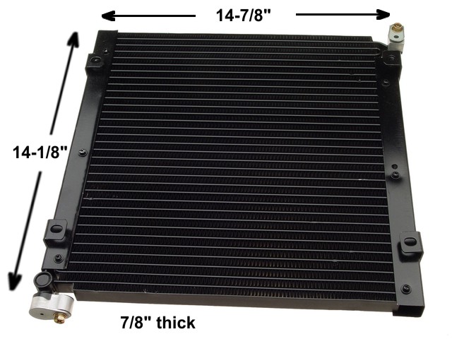 This seemed a reasonable choice for several reasons. It’s a readily-available modern parallel-flow design from a car with a small, but still larger than the 914’s, passenger compartment to cool. Its size is a good match to available electric cooling fans, and to both the available space inside the forward rear fender and the floor areas of the front trunk, should that turn out to be the best place to mount it. I could also buy a new one off of eBay for $45. No matter where I would finally mount it, I was going to need a fan and a matching shroud to get descent air flow. The Spal type VA10-AP9/C-25S, 12” low profile 12V pusher fan is a good match to the active area of the condenser, requires only a simple flat sheet for a shroud thanks to the built-in standoff mounting ears on the condenser, and adds only 2” to the thickness of the condenser when mounted. The space inside the rear fender that we’re considering is about 20” deep at the bottom, 15 ½” high, and 4 ½” wide at the inner end tapering to 5 3/8” wide at the point where the fender flare begins. The condenser will fit into this space completely, however, with the fan attached it is a very tight fit: 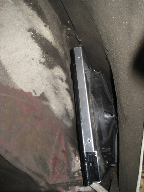 The fender cavity is only a little over an inch and a half wider than the condenser/fan combination at the inner end and about an inch more than that out near the wheel opening. The space is also open into the area under the rocker panel at the bottom, although the width of the opening is reduced to about 2 ½”. In view of the close quarters, the only possible arrangement appeared to be something like this (top view, very close to scale): 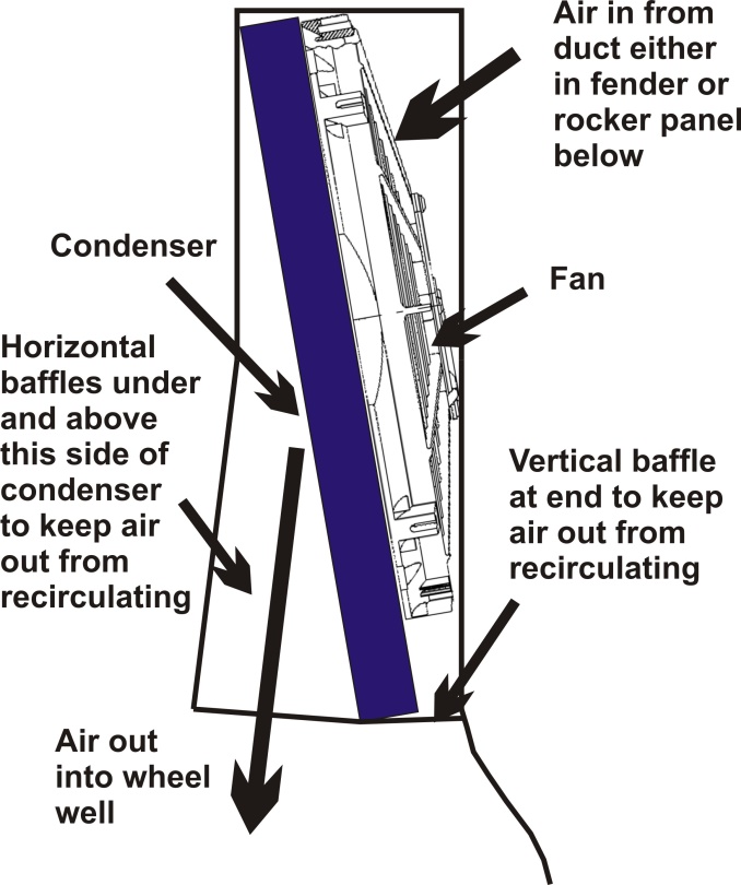 Griffiths does make a small auxiliary condenser designed, i.e. small enough, to fit in this location on 911s perpendicular to the direction of air flow shown above, but they emphasized in a phone conversation that it was not big enough to be the primary condenser in an AC system, only a supplement to the existing pair of 911 condensers. They further expressed the opinion that no system was going to be adequate on a 914 unless front-mounted so as to capture adequate air flow. Well, that was discouraging. Undaunted however, I still wanted to test out this idea with the condenser I’d chosen, and so I mocked-up the configuration shown above by making temporary baffles out of cardboard, placing the condenser and fan in the fender in the orientation shown, removing the rocker panel on the passenger side to admit as much air as possible without actually cutting a duct in the fender, powering the fan, and measuring the output air velocity with one of these little air velocity meters: 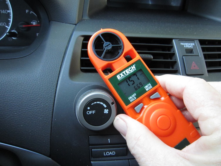 Knowing the area of the opening in the plane of measurement, I could then compute the volume air flow and compare it with that for the condenser/fan operated in an open configuration. I suppose it should not have been surprising that the flow turned out to be down more than a factor of ten compared to the open configuration, although I had hoped for more. In addition, by simply feeling with my hand I could tell that almost all of the flow was coming through the very center of the condenser, thus seriously reducing its effective size. Perhaps a large opening in the fender to admit more air would have doubled the flow reading, but this still would represent what I felt was an unacceptably low value, and cutting a large duct like that in the fender wasn’t something I was prepared to do anyway. So, back to the notion of a front trunk mounted condenser. I’m not sure why I had it so firmly in mind that a large hole in the middle of the floor of the front trunk would seriously weaken the car’s structural integrity, but I do know why I realized that it isn’t true. I happened to be walking through Rich Bontempi’s yard filled with various Porsche tubs at his shop in Redwood City, High Performance House, and noticed one with just such a hole, albeit one with a stiffening rib formed into its edge. This meant that it was an as-manufactured feature. I didn’t recognize the model it was, since most of the rest of it was covered with a rain tarp, so I asked Rich about it. “That’s a 911” he replied. Hmmmm, sure enough, looking at part 21 in illustration 801-10 in the 78-83 USA 911 catalog in PET, I could see that 911s are indeed made that way, a fact I had not appreciated. 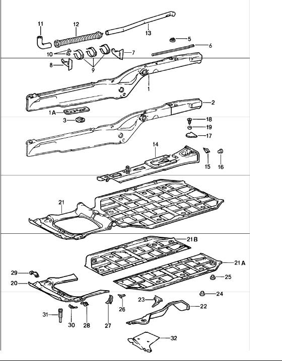 What normally closes up this hole in a 911? The gas tank, which is hardly a load-bearing member. This means that a peripheral stiffening member around any such hole in the 914’s front trunk would no doubt be sufficient to restore any structural strength sacrificed by cutting out the sheet metal. In my case, there was an additional complication to using such a hole to duct air into/out of the condenser. I had already added a front oil cooler to the car, an Earl’s oil radiator roughly the size and shape of a license plate, and had mounted it in the location of the front license plate holder rather than inside the front trunk in order to preserve usable trunk space. A shallow scoop mounted behind the cooler and countersunk into the trunk deflects the exiting air downward into the space behind the front spoiler and consumes only a little over four inches of depth inside the trunk. This allowed me to mount a space-saver spare horizontally, rather than vertically as in the 916, and preserve most of the cargo space of the stock arrangement. 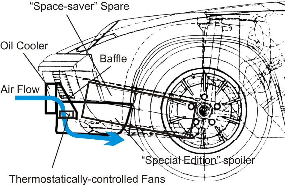 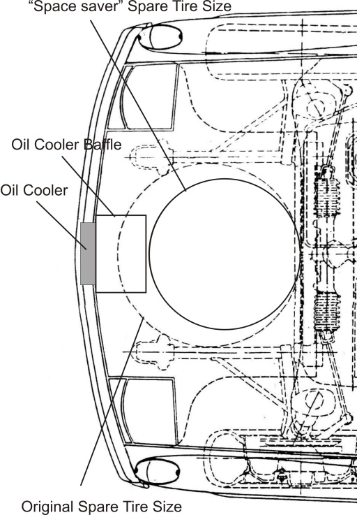 The cooler looks at first glance like the bracket for a front license plate, and I fitted an actual black plastic license plate frame around it to make it look all the more so. I also thought about suspending a small Porsche crest in the center to make it look like the cardboard frame filler that comes on new Porsches, but thought I’d better get it all working before wasting time on such minor cosmetic things. 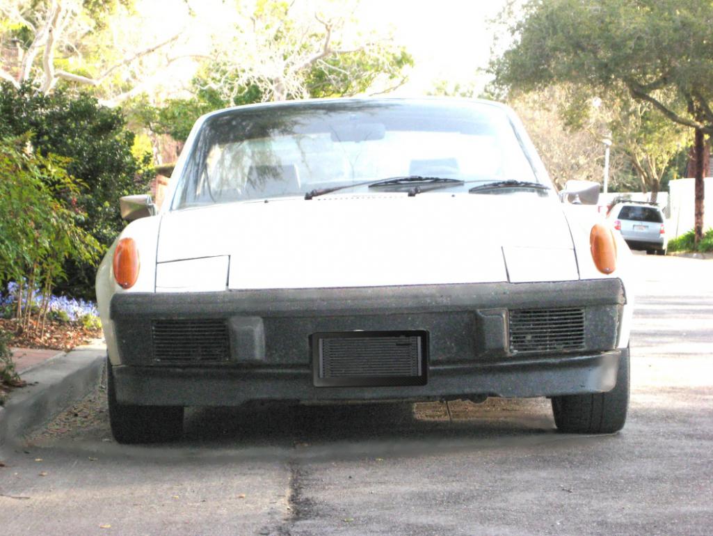 I decided on the configuration below to add the condenser. 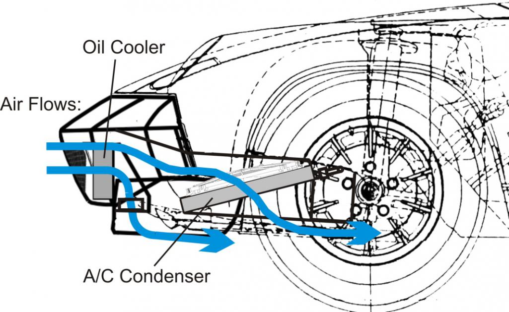 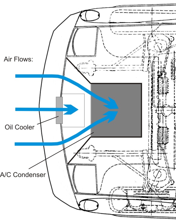 Here, I’ve dispensed with the spare tire entirely (I realized that, in 47years of owning and driving the car, I’ve never needed to mount the spare tire because of a flat), replacing it with a can of Fix-A-Flat, and filled essentially that same space with the condenser and ducting that brings air from openings on either side of the oil cooler to the condenser and its fan. The air exits through a large rectangular hole in the floor which I reinforced with a welded frame of square cross-section steel tubing. The condenser is tilted in order to keep the liquid end of it lower than the high pressure gas end, but the condenser/fan/ducting package still comes out to be no taller than the spare tire it displaced, so that I’m still left with most of the original trunk capacity. Long-term, I plan to fabricate a custom bumper extended enough to fully enclose the oil cooler and improve the looks of the front end in the bargain, at least in my humble opinion. My present conception of the shape and appearance of this bumper is reflected in the two drawings above, and in the following rendering (with apologies in advance for my meager Photoshop skills): 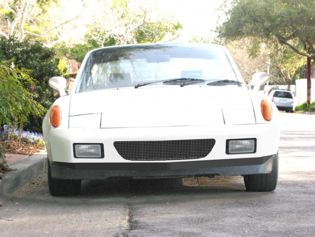 Building such a bumper will be another big project, however, so for now I just lost the ’73 rubber tits that I installed to get a little more parking protection and added a couple of screened openings in the stock bumper in their places to feed fresh air to the condenser. So, this is what the car actually looks like from the front currently: 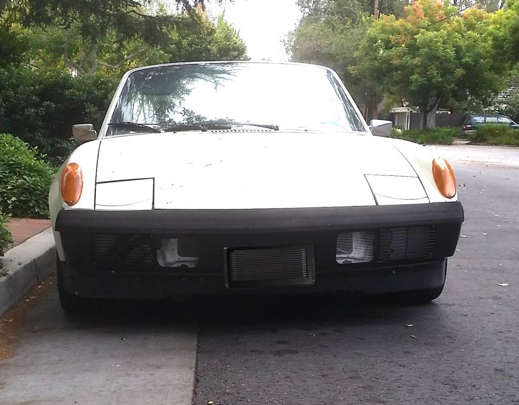 A few construction photos: Condenser and fan trial fit. You can see the inside of the oil cooler baffle at the bottom: 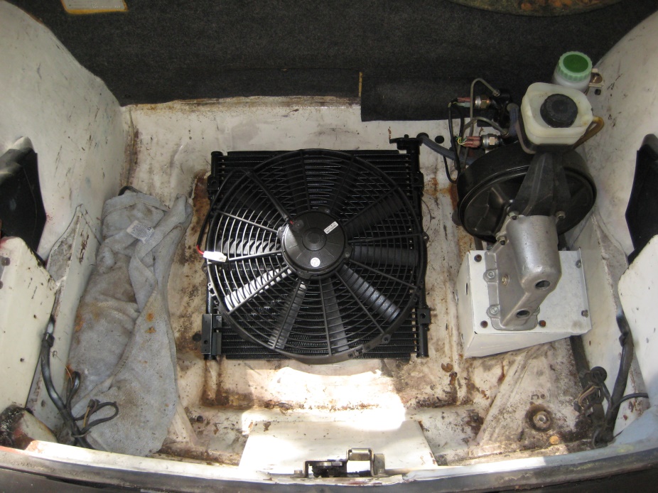 Hole cut and reinforcement added: 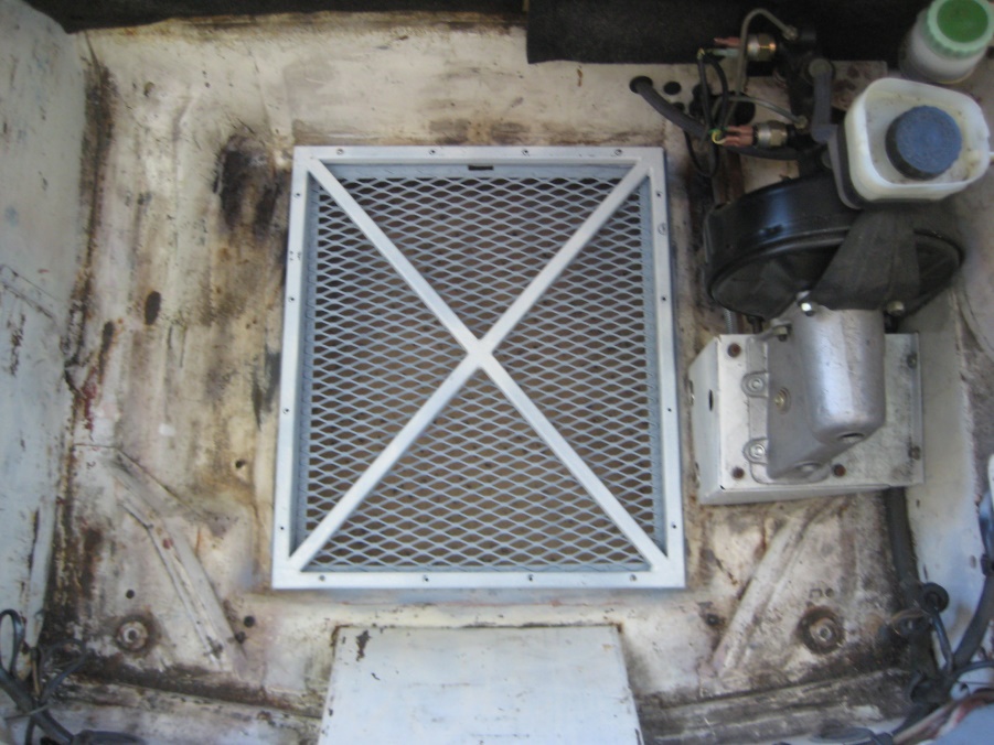 Condenser, fan, and sides of condenser baffles in place: 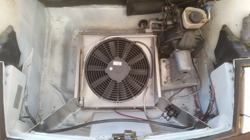 Top baffling added: 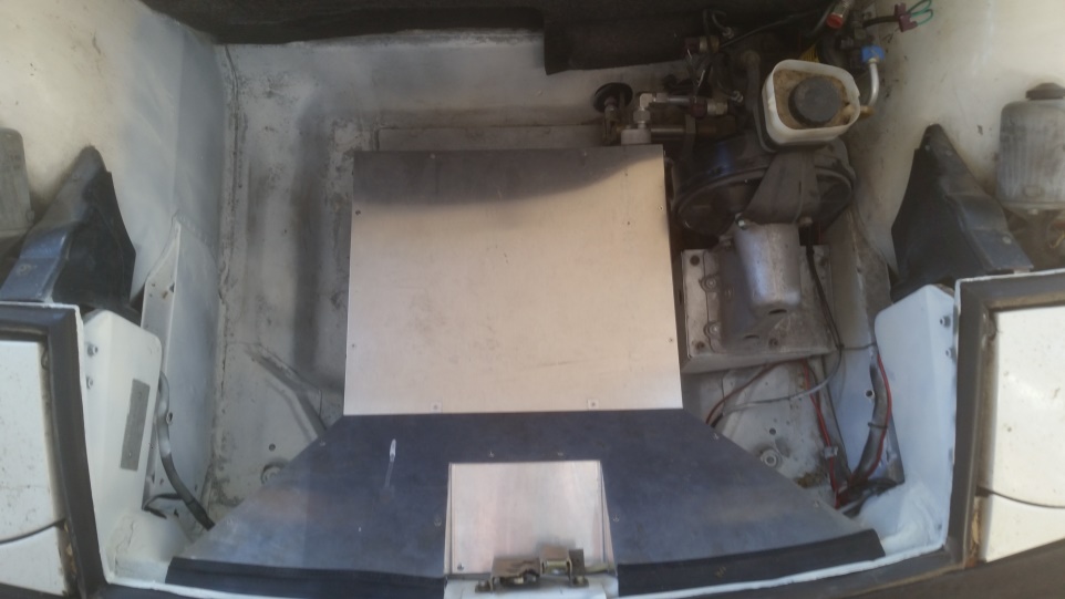 Openings in front wall of trunk in relation to oil cooler: 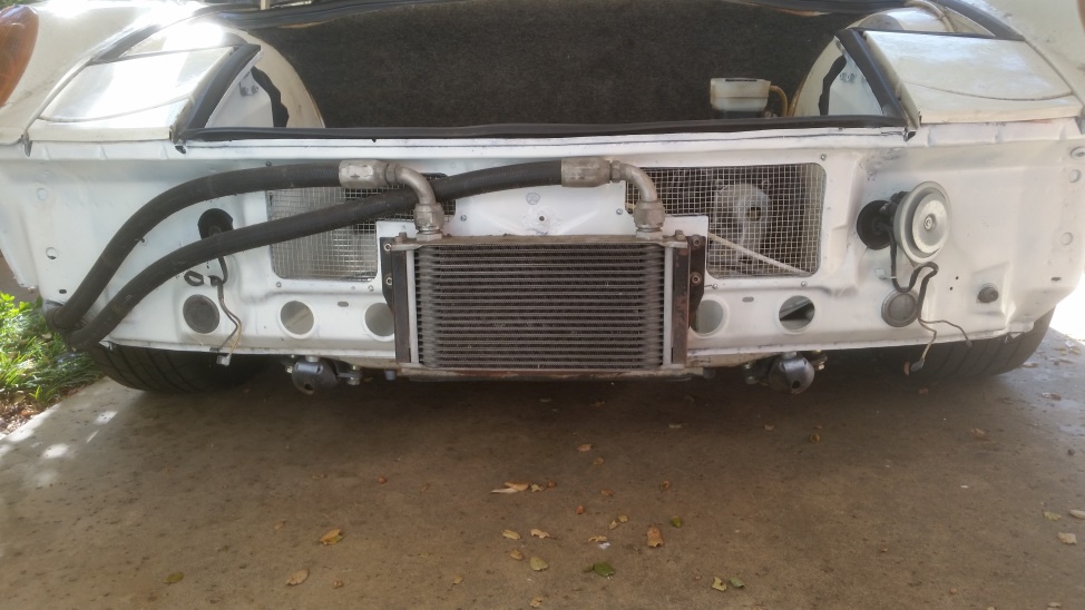 |
   |

 
|
| maf914 |
Sep 22 2017, 05:38 AM
Post
#2
|
|
Not a Guru! Group: Members Posts: 3,049 Joined: 30-April 03 From: Central Florida Member No.: 632 Region Association: None |
Great information and nice work. Thank you for posting.
|
|
|
|
|
1 User(s) are reading this topic (1 Guests and 0 Anonymous Users)
0 Members:

|
Lo-Fi Version | Time is now: 23rd April 2024 - 03:43 AM |
Invision Power Board
v9.1.4 © 2024 IPS, Inc.