|
|

|
Porsche, and the Porsche crest are registered trademarks of Dr. Ing. h.c. F. Porsche AG.
This site is not affiliated with Porsche in any way. Its only purpose is to provide an online forum for car enthusiasts. All other trademarks are property of their respective owners. |
|
|
  |
| tygaboy |
 Aug 15 2022, 09:12 AM Aug 15 2022, 09:12 AM
Post
#181
|
|
914 Guru      Group: Members Posts: 5,451 Joined: 6-October 15 From: Petaluma, CA Member No.: 19,241 Region Association: Northern California 
|
@Chris914n6 - I was toying with the idea of making a short "trunk lid" that was sized to work with the abbreviated trunk. But as @horizontally-opposed Pete points out, I'd end up with a body line in a location unrealted to any other design queues - so that's off the table. So, what to do?
@Retroracer Tony to the rescue! Let me first say that if it weren't for Tony and his "quick sketches" (which are auto art, IMO!), I likely wouldn't have hood vents on my LS build. Or, if I did, they'd certainly be less cool! So, to be clear, I regularly consulted with him on styling ideas for my LS build and he was always willing to listen to my silly "I wonder if..." then noodle up a few ideas - most of which I just love! And this build is no different: I've been talking with Tony and texting him various pics for the past few weeks. When he stopped by yesterday, he gave me this (among other drawings that I'll share later) as one of a few ideas for the engine cover/trunk. It's a leading contender at this point. Yes, minor shape and dimension changes will be needed to work in the real world, just like with his hood vents, but it's the inspiration that's most important to me. Well, that and knowing there are other folks out there that want to see this project come togther in the best possible way. Tony - Thank you, my friend! I couldn't do this without you. Literally. It's so great to get your fingerprints on this build, too. (IMG:style_emoticons/default/pray.gif) (IMG:style_emoticons/default/smilie_pokal.gif) Attached thumbnail(s) 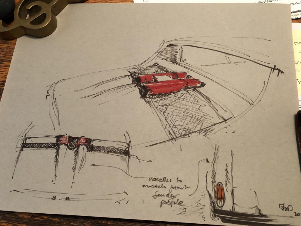
|
| Superhawk996 |
 Aug 15 2022, 09:21 AM Aug 15 2022, 09:21 AM
Post
#182
|
|
914 Guru      Group: Members Posts: 6,520 Joined: 25-August 18 From: Woods of N. Idaho Member No.: 22,428 Region Association: Galt's Gulch 
|
YES!
|
| KELTY360 |
 Aug 15 2022, 09:59 AM Aug 15 2022, 09:59 AM
Post
#183
|
|
914 Neferati      Group: Members Posts: 5,089 Joined: 31-December 05 From: Pt. Townsend, WA Member No.: 5,344 Region Association: Pacific Northwest 
|
OMG!! How perfect is that?!! (IMG:style_emoticons/default/shocked[1].gif) |
| tygaboy |
 Aug 15 2022, 06:03 PM Aug 15 2022, 06:03 PM
Post
#184
|
|
914 Guru      Group: Members Posts: 5,451 Joined: 6-October 15 From: Petaluma, CA Member No.: 19,241 Region Association: Northern California 
|
Back to the mundane stuff like getting the drive train mounted.
In a blast from the past, I spent a couple hours on the phone with my fab buddy Martin to get another set of eyeballs on the design I worked up for the cradle. If it's not already clear, I fully expect any number of folks to have significant input on this build. I have no ego around asking for/paying for help. Especially if it means the outcome is what I want it to be. But back to Martin: As expected, he had a number of great suggestions, both structurally and design-wise. Best is that, overall, we agreed the cradle approach is a solid base design. Yea! (IMG:style_emoticons/default/cheer.gif) And for those interested, the pic shows the water-to-oil heat exchanger that helps initially heat and then stabalize the trans fluid temps. The arrows are pointing at the connections for the factory, belt-driven water pump which lives at the front of the valley. You can also see how they decided to get the water into the block near each cylinder via that "spider" looking H2O distribution component (external vs the GM internal circulation approach...) as well as the braided lines that get the oil in/out to the trans. The trans fluid pump is inside the trans. So there's today's "how Ferrari decided to do it" lesson! Be preparred for a quiz tomorrow! (IMG:style_emoticons/default/laugh.gif) Still tbd if I'm going to run the factory water pump or go with an electric pump and just route to the in/out locations you see here. Just a few days into this and I can confidently state: This is WAY more complicated than just stuffing things into the chassis, because Ferrari. But hey, if it were easy, everyone would be doing it. (IMG:style_emoticons/default/shades.gif) Attached thumbnail(s) 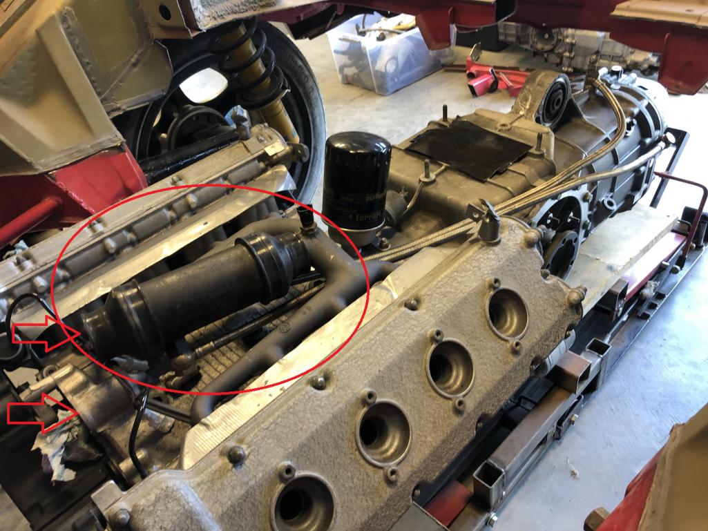
|
| tygaboy |
 Aug 15 2022, 07:09 PM Aug 15 2022, 07:09 PM
Post
#185
|
|
914 Guru      Group: Members Posts: 5,451 Joined: 6-October 15 From: Petaluma, CA Member No.: 19,241 Region Association: Northern California 
|
Seems everyone on my contributing team likes to sketch! Here's Martin's cut at one side of the cradle we noodled up. The tabbed bracket on the right if the sketch welds to the lower firewall, the "j" shape tube is one side of the cradle, the bracket on it is where the Ferrari engine mount sits and the part with the "?" and arrow is the rear mounting bracket that'll weld on between the 914 factory trans mount/cross bar and the round tube cross bar you saw in the earlier pics.
Then once the headers are sorted (which is a "whole 'nother" packaging challenge), I'd like to see a bar that ties from the long, just ahead of the suspension console, down to the J tube at/near the engine mounting pad. Coming along and nearly to the point where it's time to start fabbing all this. Exciting times! Attached image(s) 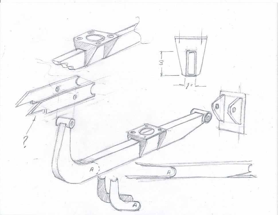
|
| bkrantz |
 Aug 15 2022, 08:55 PM Aug 15 2022, 08:55 PM
Post
#186
|
|
914 Guru      Group: Members Posts: 8,142 Joined: 3-August 19 From: SW Colorado Member No.: 23,343 Region Association: Rocky Mountains 
|
You know, if you really want to give old man Enzo (and old man Ferdinand and just about everyone else) a heart attack, you could turn the drive train around, and make a rear-engine VW-Porarri.
|
| Krieger |
 Aug 15 2022, 10:46 PM Aug 15 2022, 10:46 PM
Post
#187
|
|
Advanced Member     Group: Members Posts: 4,763 Joined: 24-May 04 From: Santa Rosa CA Member No.: 2,104 Region Association: None 
|
WOW! Tony's sketches of the humps are a perfectly natural addition!
|
| Cairo94507 |
 Aug 16 2022, 06:23 AM Aug 16 2022, 06:23 AM
Post
#188
|
|
Michael           Group: Members Posts: 10,091 Joined: 1-November 08 From: Auburn, CA Member No.: 9,712 Region Association: Northern California 
|
I agree with Andy, love Tony's sketch and that he is matching the "humps" to the front fenders. Looks great. (IMG:style_emoticons/default/beerchug.gif)
|
| tygaboy |
 Aug 17 2022, 08:59 AM Aug 17 2022, 08:59 AM
Post
#189
|
|
914 Guru      Group: Members Posts: 5,451 Joined: 6-October 15 From: Petaluma, CA Member No.: 19,241 Region Association: Northern California 
|
Design refinement. After more chassis clearancing and getting the drive train in what I'm pretty sure is final location, I bolted on the alternator. Good thing because is sits right where I was thinking a front engine mount could go. Not that I was close to welding anything, but... Sort of a "pants first, then shoes" moment. But you know me: You're going to get full transparency as I make my way through this.
Attached thumbnail(s) 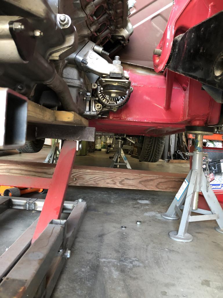 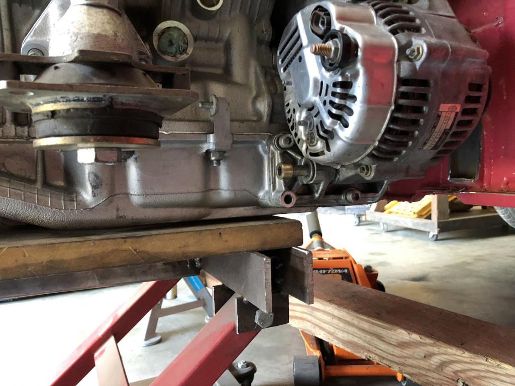
|
| tygaboy |
 Aug 17 2022, 09:06 AM Aug 17 2022, 09:06 AM
Post
#190
|
|
914 Guru      Group: Members Posts: 5,451 Joined: 6-October 15 From: Petaluma, CA Member No.: 19,241 Region Association: Northern California 
|
I passed this new info and the pics along to Martin, we kicked around a couple ideas and he sent a sketch of the latest thinking. Note it's not to scale, just "to concept". The plan is 3" x 1" .095 wall for those main tubes, even though the sketch makes them look far larger.
It's just not possible to get a cross bar to sit directly under the engine mounts so the one you see fits in a raised section just ahead of the trans, a bit behind the mounts. And yes, this drawing it's missing the rear section. Which is OK as it's far more straight forward than working out these main engine mounts. Today's IRL exercise will be to get some tubes mocked into position and work out more accurate dimensions. Hey, it's a process. And this is the part I just LOVE. Driving them is fine, I like makin' stuff! (IMG:style_emoticons/default/sawzall-smiley.gif) (IMG:style_emoticons/default/smash.gif) (IMG:style_emoticons/default/welder.gif) Attached thumbnail(s) 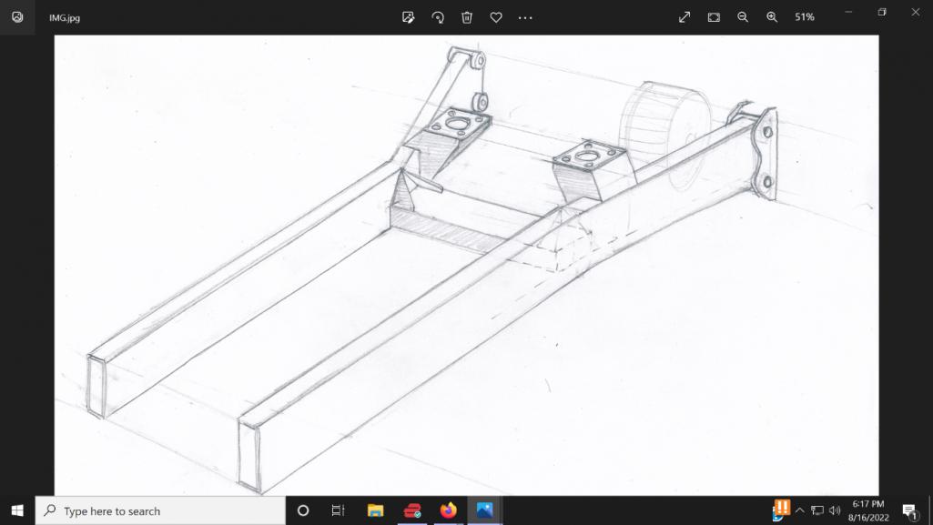
|
| ClayPerrine |
 Aug 17 2022, 03:26 PM Aug 17 2022, 03:26 PM
Post
#191
|
|
Life's been good to me so far.....                Group: Admin Posts: 15,901 Joined: 11-September 03 From: Hurst, TX. Member No.: 1,143 Region Association: NineFourteenerVille 
|
Hey, it's a process. And this is the part I just LOVE. Driving them is fine, I like makin' suff! (IMG:style_emoticons/default/sawzall-smiley.gif) (IMG:style_emoticons/default/smash.gif) (IMG:style_emoticons/default/welder.gif) (IMG:style_emoticons/default/agree.gif) I am exactly the same. I can't leave well enough alone. I even have plans on how to put a full Cayman rear suspension under a 914 chassis........ (IMG:style_emoticons/default/idea.gif) We definitely need a bad idea smiley. Clay |
| tygaboy |
 Aug 20 2022, 09:26 AM Aug 20 2022, 09:26 AM
Post
#192
|
|
914 Guru      Group: Members Posts: 5,451 Joined: 6-October 15 From: Petaluma, CA Member No.: 19,241 Region Association: Northern California 
|
When you don't have a 3d scanner, skills with Fusion 360 (or the like) or even a lift:
1. stand there looking at the drive train in the chassis 2. imagine how some design might work (IMG:style_emoticons/default/idea.gif) 3. try and keep track of things that aren't there - shift cables, water lines, wiring, exhaust system... (IMG:style_emoticons/default/blink.gif) 4. crawl around / scoot around / reach around (IMG:style_emoticons/default/lol-2.gif) trying to measure 5. mock up ideas with scrap and other random parts 6. take pics 7. get on the phone with Martin, email pics and noodle on the latest info 8. wait a bit for Martin to email his latest drawing 9. Repeat steps 2 through 8 Slower than it might otherwise be, but we're making progress. These latest designs account for the engine cradle and the rear transmission mounting system (TMS) - it will live between the rear suspension towers - but they're missing the mount where the engine cradle's vertical elements tie to the TMS. I've sent a rough drawing to Martin with an idea I like and expect later today he'll send an updated set of drawings. Almost ready to cut parts! As I mentioned earlier, mounting this drive train is turning out to be a bit more complicated than I expected. I suspect this will be a recurring theme on this build. Attached thumbnail(s) 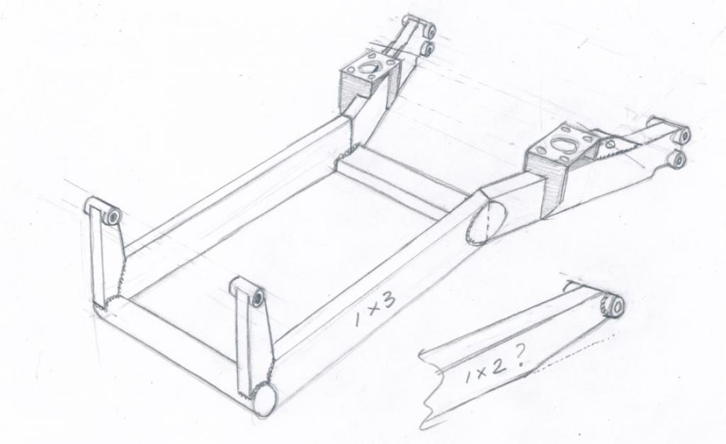 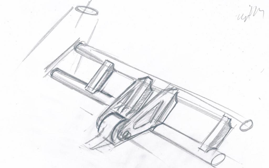
|
| tygaboy |
 Aug 20 2022, 12:15 PM Aug 20 2022, 12:15 PM
Post
#193
|
|
914 Guru      Group: Members Posts: 5,451 Joined: 6-October 15 From: Petaluma, CA Member No.: 19,241 Region Association: Northern California 
|
My, how quickly plans can change. Another round of planning w/Martin this morning and...
To optimize the Ferrari trans hanger mount, and with all the other stuff planned for this build, it started making more sense to lose the factory trunk and trans cross bar. So out it comes. Attached thumbnail(s) 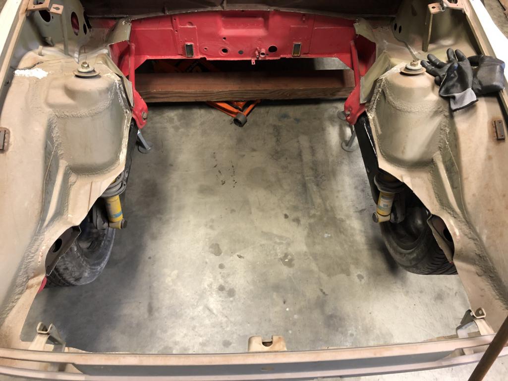
|
| tygaboy |
 Aug 20 2022, 12:18 PM Aug 20 2022, 12:18 PM
Post
#194
|
|
914 Guru      Group: Members Posts: 5,451 Joined: 6-October 15 From: Petaluma, CA Member No.: 19,241 Region Association: Northern California 
|
And a better, no-twisting-moment, trans mount system can be installed. Just mocked in approximate location, as you can see, but the transmission mounting tab will sit between these bars. Structurally better, for sure.
I'll fab a removable trunk floor/wall that can seal against the trunk lid but be taken out to show off all the mechanicalness. Attached thumbnail(s) 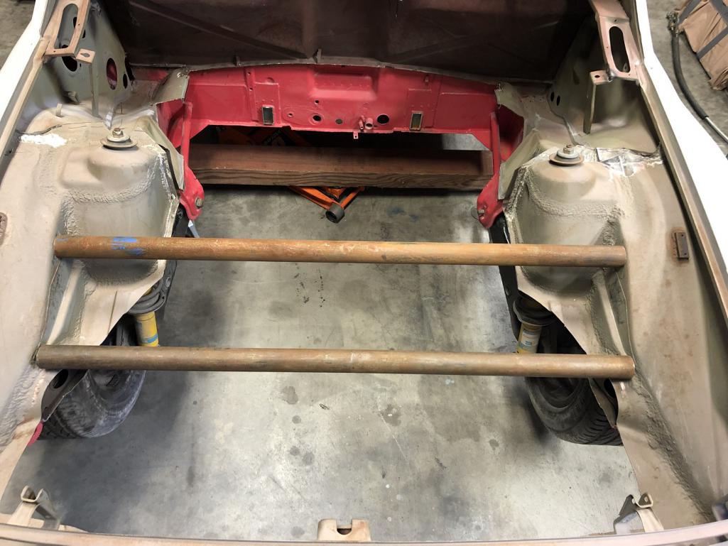
|
| tygaboy |
 Aug 20 2022, 12:21 PM Aug 20 2022, 12:21 PM
Post
#195
|
|
914 Guru      Group: Members Posts: 5,451 Joined: 6-October 15 From: Petaluma, CA Member No.: 19,241 Region Association: Northern California 
|
And the updated, not-to-scale sketch of the trans mount with the bracket to connect the engine cradle vertical. One of those tabs on each side of the vertical.
Attached image(s) 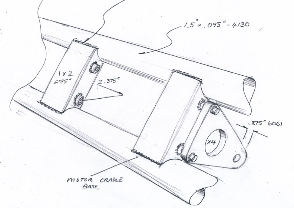
|
| tygaboy |
 Aug 20 2022, 12:25 PM Aug 20 2022, 12:25 PM
Post
#196
|
|
914 Guru      Group: Members Posts: 5,451 Joined: 6-October 15 From: Petaluma, CA Member No.: 19,241 Region Association: Northern California 
|
And I hope you enjoy seeing this level of development process vs me just posting when something is actually complete. I like to document for posterity's sake.
|
| davep |
 Aug 20 2022, 02:16 PM Aug 20 2022, 02:16 PM
Post
#197
|
|
914 Historian      Group: Benefactors Posts: 5,212 Joined: 13-October 03 From: Burford, ON, N0E 1A0 Member No.: 1,244 Region Association: Canada  |
You bet, this is an Epic build!
|
| Montreal914 |
 Aug 20 2022, 07:18 PM Aug 20 2022, 07:18 PM
Post
#198
|
|
Senior Member    Group: Members Posts: 1,700 Joined: 8-August 10 From: Claremont, CA Member No.: 12,023 Region Association: Southern California 
|
Although I can see the performance benefits, I am not into conversions with with non-P power train.
BUT, this one is clearly something else! (IMG:style_emoticons/default/sunglasses.gif) Please continue to share all of the development and these wonderful period correct work of art hand made sketches (IMG:style_emoticons/default/pray.gif). I grew up learning mechanical engineering from my dad (mechanical draftsman and all around craft person) and always admired his hand sketch skills. No modern CAD can transmit the artistic aspect of engineering like those hand sketches. You and Martin make a wonderful duo. This will be a nicely engineered and well built car! (IMG:style_emoticons/default/smash.gif) (IMG:style_emoticons/default/smilie_pokal.gif) |
| tazz9924 |
 Aug 20 2022, 09:22 PM Aug 20 2022, 09:22 PM
Post
#199
|
|
Senior Member    Group: Members Posts: 716 Joined: 31-May 15 From: Mooresville NC Member No.: 18,779 Region Association: None |
When you don't have a 3d scanner, skills with Fusion 360 (or the like) or even a lift: 1. stand there looking at the drive train in the chassis 2. imagine how some design might work (IMG:style_emoticons/default/idea.gif) 3. try and keep track of things that aren't there - shift cables, water lines, wiring, exhaust system... (IMG:style_emoticons/default/blink.gif) 4. crawl around / scoot around / reach around (IMG:style_emoticons/default/lol-2.gif) trying to measure 5. mock up ideas with scrap and other random parts 6. take pics 7. get on the phone with Martin, email pics and noodle on the latest info 8. wait a bit for Martin to email his latest drawing 9. Repeat steps 2 through 8 Slower than it might otherwise be, but we're making progress. These latest designs account for the engine cradle and the rear transmission mounting system (TMS) - it will live between the rear suspension towers - but they're missing the mount where the engine cradle's vertical elements tie to the TMS. I've sent a rough drawing to Martin with an idea I like and expect later today he'll send an updated set of drawings. Almost ready to cut parts! As I mentioned earlier, mounting this drive train is turning out to be a bit more complicated than I expected. I suspect this will be a recurring theme on this build. My process is very similar except when step 7 comes around, instead of getting on the phone i get on the computer and want to punch it sometimes. Then realize i messed it up hopefully before waiting a week for laser cut parts to arrive and repeat. |
| nathanxnathan |
 Aug 21 2022, 12:30 PM Aug 21 2022, 12:30 PM
Post
#200
|
|
Member   Group: Members Posts: 294 Joined: 16-February 18 From: Laguna Beach, CA Member No.: 21,899 Region Association: Southern California |
I love the drawings — speaking my language (IMG:style_emoticons/default/biggrin.gif)
|
  |
2 User(s) are reading this topic (2 Guests and 0 Anonymous Users)
0 Members:

|
Lo-Fi Version | Time is now: 23rd November 2024 - 02:34 AM |
Invision Power Board
v9.1.4 © 2024 IPS, Inc.


