|
|

|
Porsche, and the Porsche crest are registered trademarks of Dr. Ing. h.c. F. Porsche AG.
This site is not affiliated with Porsche in any way. Its only purpose is to provide an online forum for car enthusiasts. All other trademarks are property of their respective owners. |
|
|
  |
| tygaboy |
 Aug 26 2022, 09:32 AM Aug 26 2022, 09:32 AM
Post
#221
|
|
914 Guru      Group: Members Posts: 5,451 Joined: 6-October 15 From: Petaluma, CA Member No.: 19,241 Region Association: Northern California 
|
Messy, boring, necessary prep for the outer spreader plate.
Attached thumbnail(s) 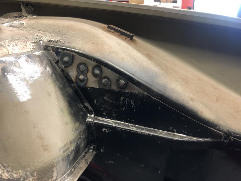
|
| ClayPerrine |
 Aug 26 2022, 11:54 AM Aug 26 2022, 11:54 AM
Post
#222
|
|
Life's been good to me so far.....                Group: Admin Posts: 15,901 Joined: 11-September 03 From: Hurst, TX. Member No.: 1,143 Region Association: NineFourteenerVille 
|
Just a suggestion... Get Ferrari Modena brakes for it. They are Brembo monoblocks, the exact same as the Boxster brakes, but they have Ferrari on the face of them. So you don't have to engineer anything, just bolt them on. Put them behind Fuchs with the Porsche crest in the center. That would mess with both the Porsche and Ferrari purists big time. (IMG:style_emoticons/default/happy11.gif) Clay @ClayPerrine Clay, Well timed, sir! The conversation and initial decison about caliper labeling happened yesterday afternoon! And what is that decision? Well, you'll just have to stay tuned to hear about it and a couple of other big changes in direction... (IMG:style_emoticons/default/happy11.gif) (IMG:style_emoticons/default/shades.gif) You have probably heard the old saying "Great minds run in the same channel." In our case, too bad it's the gutter. (IMG:style_emoticons/default/laugh.gif) Clay |
| tygaboy |
 Aug 26 2022, 05:34 PM Aug 26 2022, 05:34 PM
Post
#223
|
|
914 Guru      Group: Members Posts: 5,451 Joined: 6-October 15 From: Petaluma, CA Member No.: 19,241 Region Association: Northern California 
|
And there's the right side, outer spreader plate plug welded. It'll get some skip welds along its edges, too. I just haven't gotten to that.
And to appease the fabrication gods so they ensure nothing fails, at the completion of any particular area, it's always a good idea to say, out loud, "OK! That's not going anywhere!" (IMG:style_emoticons/default/pray.gif) Note that all the plug welds will be sanded smooth and all edges will be seam sealed. Attached thumbnail(s) 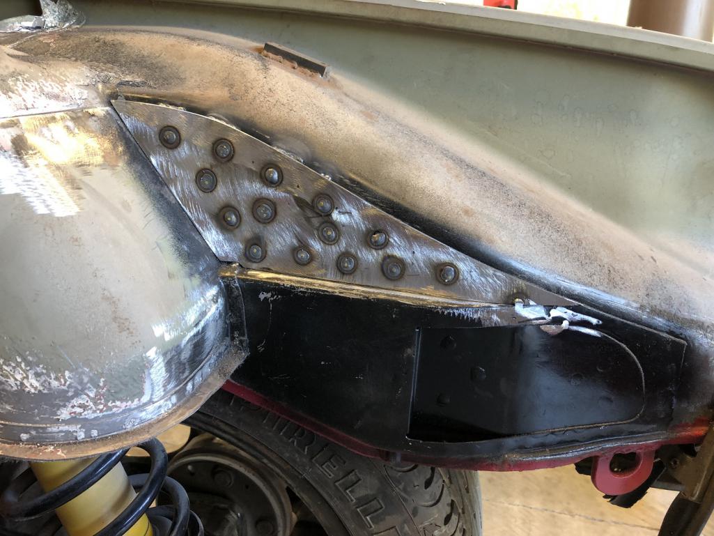 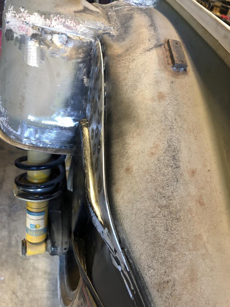
|
| tygaboy |
 Aug 26 2022, 05:36 PM Aug 26 2022, 05:36 PM
Post
#224
|
|
914 Guru      Group: Members Posts: 5,451 Joined: 6-October 15 From: Petaluma, CA Member No.: 19,241 Region Association: Northern California 
|
Left side upper, inner plate plug welded, sanded, primed and ready for the outer spreader.
Attached thumbnail(s) 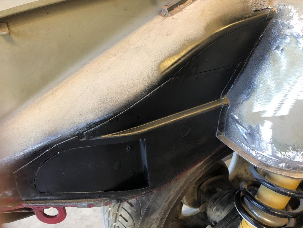
|
| tygaboy |
 Aug 26 2022, 05:41 PM Aug 26 2022, 05:41 PM
Post
#225
|
|
914 Guru      Group: Members Posts: 5,451 Joined: 6-October 15 From: Petaluma, CA Member No.: 19,241 Region Association: Northern California 
|
Without going into the excrutiating details I'm working to understand, it's V4-ish of the rear transmission mount system, including some style points for the upper shock mount area. Just kicking ideas around...
Attached thumbnail(s) 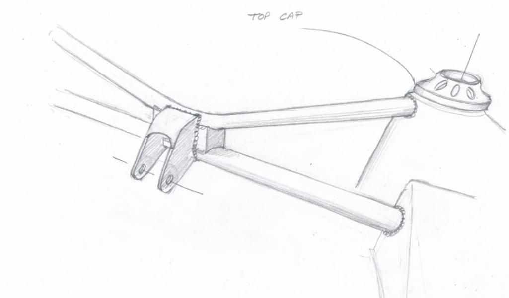
|
| tygaboy |
 Aug 27 2022, 06:02 PM Aug 27 2022, 06:02 PM
Post
#226
|
|
914 Guru      Group: Members Posts: 5,451 Joined: 6-October 15 From: Petaluma, CA Member No.: 19,241 Region Association: Northern California 
|
Left side upper spreader in place. I clamp near each hole as I'm plug welding it to be sure the plate is firmly contacting the parent material.
Attached image(s) 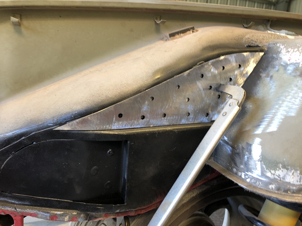
|
| tygaboy |
 Aug 27 2022, 06:03 PM Aug 27 2022, 06:03 PM
Post
#227
|
|
914 Guru      Group: Members Posts: 5,451 Joined: 6-October 15 From: Petaluma, CA Member No.: 19,241 Region Association: Northern California 
|
Both upper spreaders are welded and sanded.
Attached image(s) 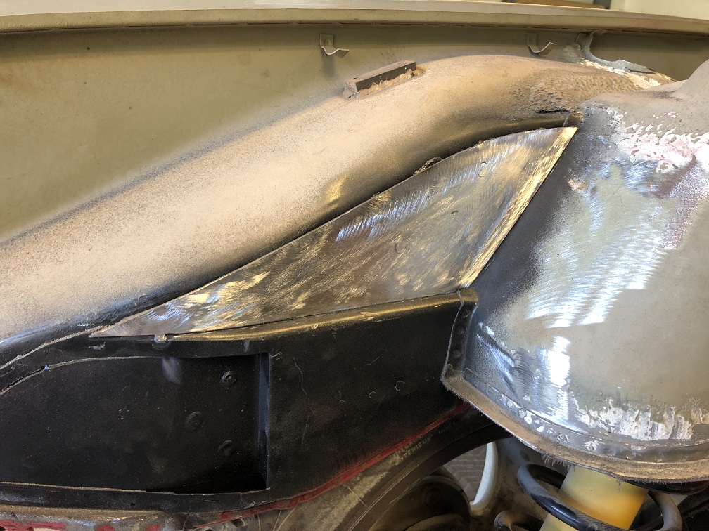 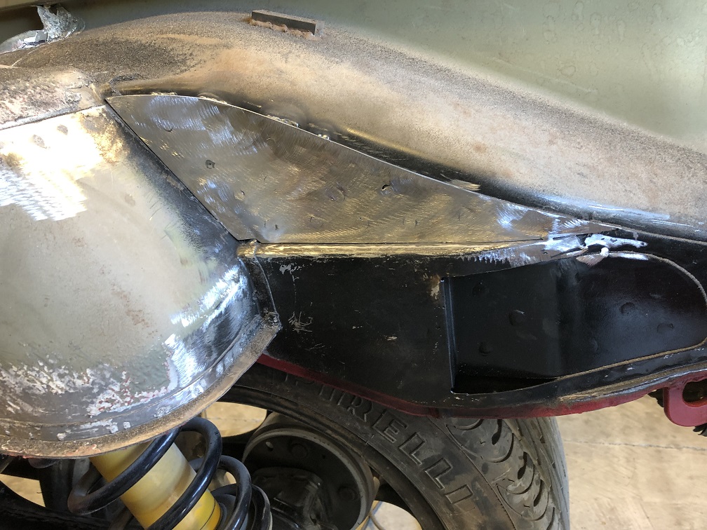
|
| tygaboy |
 Aug 27 2022, 06:05 PM Aug 27 2022, 06:05 PM
Post
#228
|
|
914 Guru      Group: Members Posts: 5,451 Joined: 6-October 15 From: Petaluma, CA Member No.: 19,241 Region Association: Northern California 
|
Now to determine the location for the upper trans mount cross bar.
I thought my LS set up was cool, but this thing...man. (IMG:style_emoticons/default/wub.gif) Attached thumbnail(s) 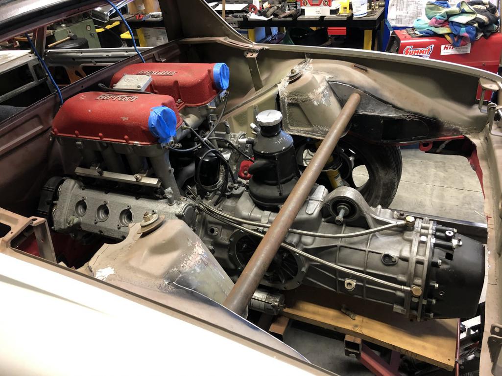
|
| tygaboy |
 Aug 28 2022, 11:25 AM Aug 28 2022, 11:25 AM
Post
#229
|
|
914 Guru      Group: Members Posts: 5,451 Joined: 6-October 15 From: Petaluma, CA Member No.: 19,241 Region Association: Northern California 
|
Engine mounting fun:
The tricky part is that the Ferrari has a chassis that's shaped to support the engine mounts - these supports are a fixed part of the chassis. And becaure the engine is wider at the top than the mount width, the drive train has to come out the top of the car. That's not something I want to have to do, if I can at all help it. So I have to come up with an intermediate "something" that's removeable and allows the engine to be lowered out the bottom. Much noodling and head scratching has yeilded this design for what I've taken to call the "landing pads". Essentially, it's a permanent addition to the 914 chassis that's as wide as it can be while still allowing the engine to clear. Then we have a removable chunk of a mount that connects to this structure and serves as the landing pad. This structure isn't quite final as that tube that heads outward is only a place-holder and will need to angle up to the long. There will also be gusseting from this up to as high as practical on the chassis / cage tubing to combat any twisting force. Today's goal is to cut a few of these pieces and mock this up in the chassis. Note that this current design eliminates any tubing from the motor mount rearward: no more cradle approach. This eliminates any potential interference or "no-go" zones for things like the axles, exhaust or, in the case of the right side, the shifter cables. Attached image(s) 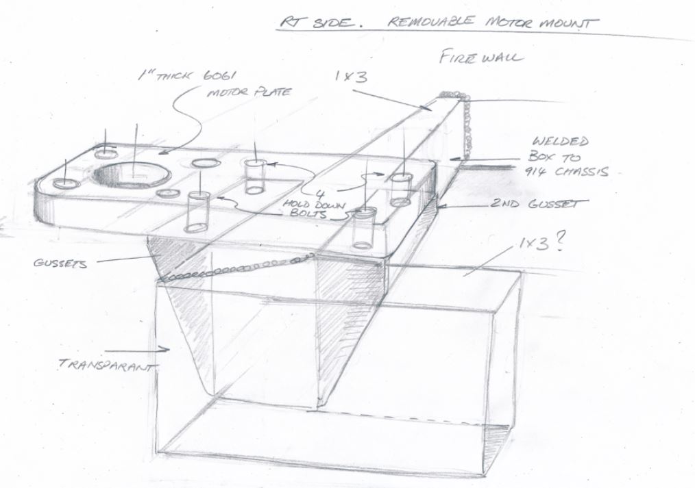
|
| Van B |
 Aug 28 2022, 01:14 PM Aug 28 2022, 01:14 PM
Post
#230
|
|
Senior Member    Group: Members Posts: 1,618 Joined: 20-October 21 From: WR, GA Member No.: 26,011 Region Association: None 
|
Random suggestion: you should count all the times you had to put the powertrain in place for mock ups. I’ve often wondered how many times should be expected for a custom build… probably close to 100 or more by the time it’s all done!
|
| tygaboy |
 Aug 28 2022, 02:17 PM Aug 28 2022, 02:17 PM
Post
#231
|
|
914 Guru      Group: Members Posts: 5,451 Joined: 6-October 15 From: Petaluma, CA Member No.: 19,241 Region Association: Northern California 
|
Random suggestion: you should count all the times you had to put the powertrain in place for mock ups. I’ve often wondered how many times should be expected for a custom build… probably close to 100 or more by the time it’s all done! That's the sort of thing, along with adding up receipts, that I really do not want to do! (IMG:style_emoticons/default/blink.gif) (IMG:style_emoticons/default/laugh.gif) But to date, I'm probably approaching ten to get to this point. Fortunately, Most of what's been going on requires the drive train be in place. One of the ideas I had was to make a fixture that duplicates the motor mount locations and the trans mount tab. It'd be made such that when it was leveled front/back and side/side in the leveled chassis, all I'd have to know is the distance from the fire wall to the motor mount location and I could build all the mounts to the fixture. |
| Chris914n6 |
 Aug 28 2022, 03:44 PM Aug 28 2022, 03:44 PM
Post
#232
|
|
Jackstands are my life.     Group: Members Posts: 3,413 Joined: 14-March 03 From: Las Vegas, NV Member No.: 431 Region Association: Southwest Region |
I simplified it. Loosen the motor mount bolt, remove 4 bolts, repeat, drop. Weld the nuts to the chassis mount to make it easier. Pretty much standard formula for cars with multiple engine options. Tough part is the chassis mount as that area is not the strongest or best shaped part of the car. The trailing arm branch might need to be repurposed round tube. If you are concerned about bolt sheer add a dowel pin or two, plus they work great as locating pins.
(IMG:http://www.914world.com/bbs2/uploads_offsite/live.staticflickr.com-431-1661723087.1.jpg) Random suggestion: you should count all the times you had to put the powertrain in place for mock ups. I’ve often wondered how many times should be expected for a custom build… probably close to 100 or more by the time it’s all done! I only did it a handful of times. Once the trunk was trimmed and the motor was is in it's final place I cut and welded the crossbar together in car. Helps that I kept the 914 trans and had room under the motor for a typical crossbar. I had the trans bolted in and a crossbar on top of the car with the motor suspended by straps -- plenty of room under to move around. HTH |
| Van B |
 Aug 28 2022, 05:35 PM Aug 28 2022, 05:35 PM
Post
#233
|
|
Senior Member    Group: Members Posts: 1,618 Joined: 20-October 21 From: WR, GA Member No.: 26,011 Region Association: None 
|
Random suggestion: you should count all the times you had to put the powertrain in place for mock ups. I’ve often wondered how many times should be expected for a custom build… probably close to 100 or more by the time it’s all done! That's the sort of thing, along with adding up receipts, that I really do not want to do! (IMG:style_emoticons/default/blink.gif) (IMG:style_emoticons/default/laugh.gif) But to date, I'm probably approaching ten to get to this point. Fortunately, Most of what's been going on requires the drive train be in place. One of the ideas I had was to make a fixture that duplicates the motor mount locations and the trans mount tab. It'd be made such that when it was leveled front/back and side/side in the leveled chassis, all I'd have to know is the distance from the fire wall to the motor mount location and I could build all the mounts to the fixture. Oh man, I don’t EVER add up receipts! I hear you there for sure (IMG:style_emoticons/default/beerchug.gif) |
| tygaboy |
 Aug 28 2022, 05:48 PM Aug 28 2022, 05:48 PM
Post
#234
|
|
914 Guru      Group: Members Posts: 5,451 Joined: 6-October 15 From: Petaluma, CA Member No.: 19,241 Region Association: Northern California 
|
Cut the lower spreader outline to shape, clamp it to the chassis at the front and start working it to get the needed curve.
Attached thumbnail(s) 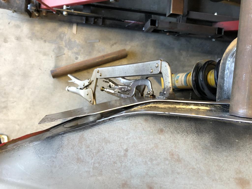
|
| tygaboy |
 Aug 28 2022, 05:49 PM Aug 28 2022, 05:49 PM
Post
#235
|
|
914 Guru      Group: Members Posts: 5,451 Joined: 6-October 15 From: Petaluma, CA Member No.: 19,241 Region Association: Northern California 
|
All shaped and curved and clamped in place to verify fit in all areas. It turned out nicely.
Attached thumbnail(s) 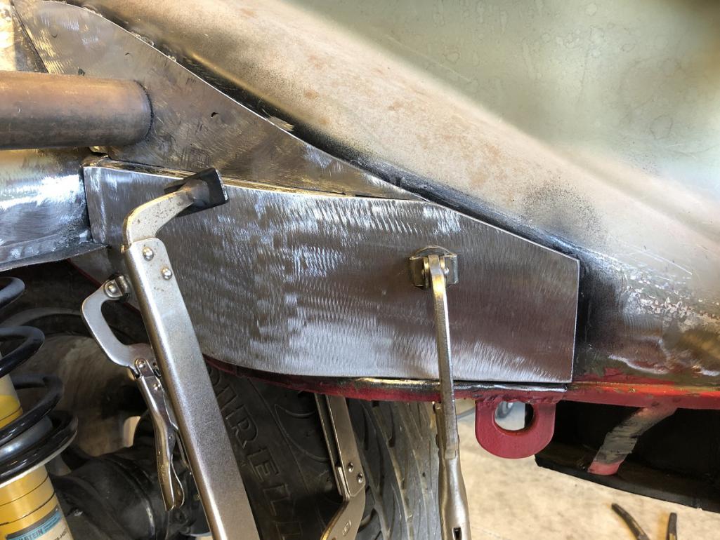
|
| tygaboy |
 Aug 28 2022, 05:51 PM Aug 28 2022, 05:51 PM
Post
#236
|
|
914 Guru      Group: Members Posts: 5,451 Joined: 6-October 15 From: Petaluma, CA Member No.: 19,241 Region Association: Northern California 
|
All plug welded and ready for sanding. Repeat on the other side and add a bit of edge welding and I'll be ready to add the rear cross bars. Things are moving right along! (IMG:style_emoticons/default/piratenanner.gif)
Attached thumbnail(s) 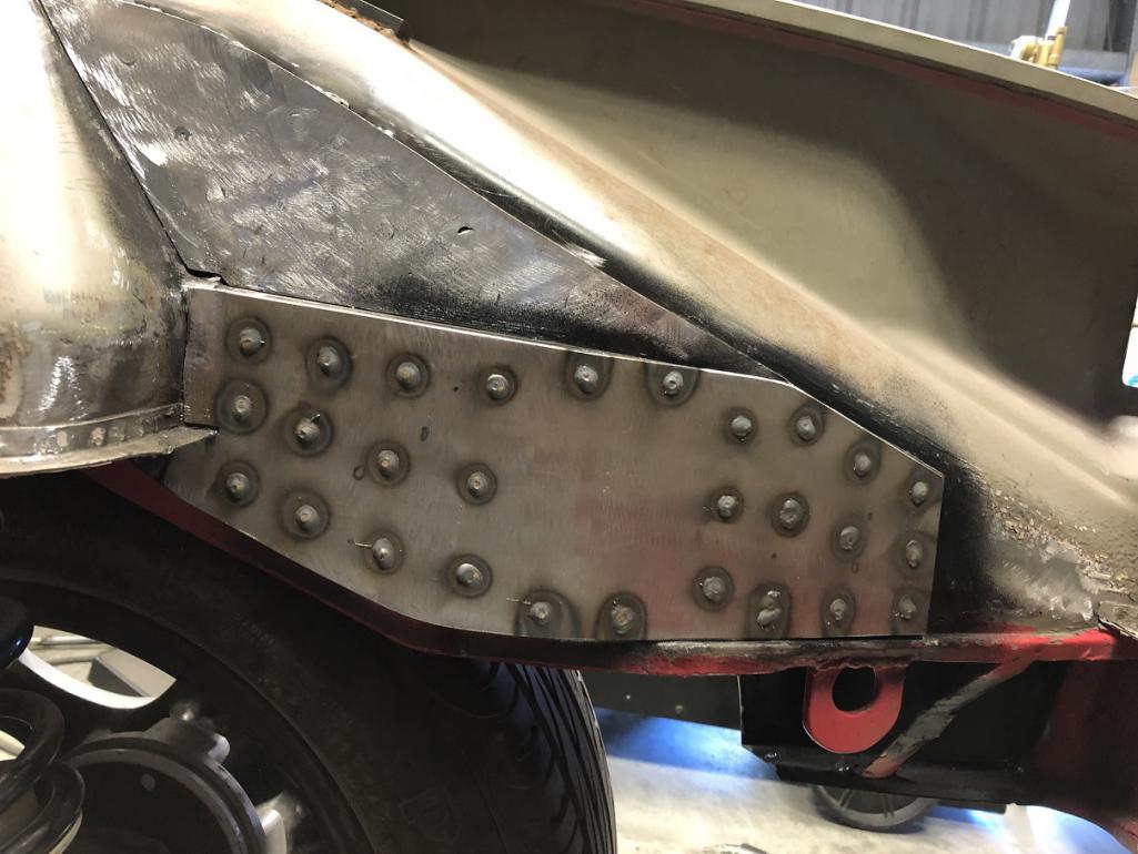
|
| tygaboy |
 Aug 28 2022, 05:55 PM Aug 28 2022, 05:55 PM
Post
#237
|
|
914 Guru      Group: Members Posts: 5,451 Joined: 6-October 15 From: Petaluma, CA Member No.: 19,241 Region Association: Northern California 
|
I simplified it. Loosen the motor mount bolt, remove 4 bolts, repeat, drop. Weld the nuts to the chassis mount to make it easier. Pretty much standard formula for cars with multiple engine options. Tough part is the chassis mount as that area is not the strongest or best shaped part of the car. The trailing arm branch might need to be repurposed round tube. If you are concerned about bolt sheer add a dowel pin or two, plus they work great as locating pins. HTH @Chris914n6 - Thanks for the input. It's certainly a process and yep, all the odd shapes make it a bit more complex. In the end, whatever the design ends up being, it'll be over built for safety's sake. |
| tygaboy |
 Sep 4 2022, 02:48 PM Sep 4 2022, 02:48 PM
Post
#238
|
|
914 Guru      Group: Members Posts: 5,451 Joined: 6-October 15 From: Petaluma, CA Member No.: 19,241 Region Association: Northern California 
|
Careful what you wish for. I thought it was a super duper thing that the Ferrari transmission output flanges were higher than the Boxster S. Turns out they are really high. Too high? I'm working on figuring out exactly this.
Here's a really rough mock up with the drive train at proper-ish height in the chassis and the trailing arm set to approximate ride height. Because of the output flange height, the wheel-side CV will never be higher than the trans output CV; it's all droop, all the time. What I need to work out is: Can a 930 CV (which has a max limit of 28 degrees) stay in range during operation? I'm pretty sure I'll have to add limit straps to stop things drooping too far when I jack the rear wheels off the ground. It may also require lowering the drive train in the chassis and building a rub bar/skid plate. It wouldn't be any worse than doing a dropped floor, in terms of ground clearance. So. Many. Items. To. Work. Out. Attached thumbnail(s) 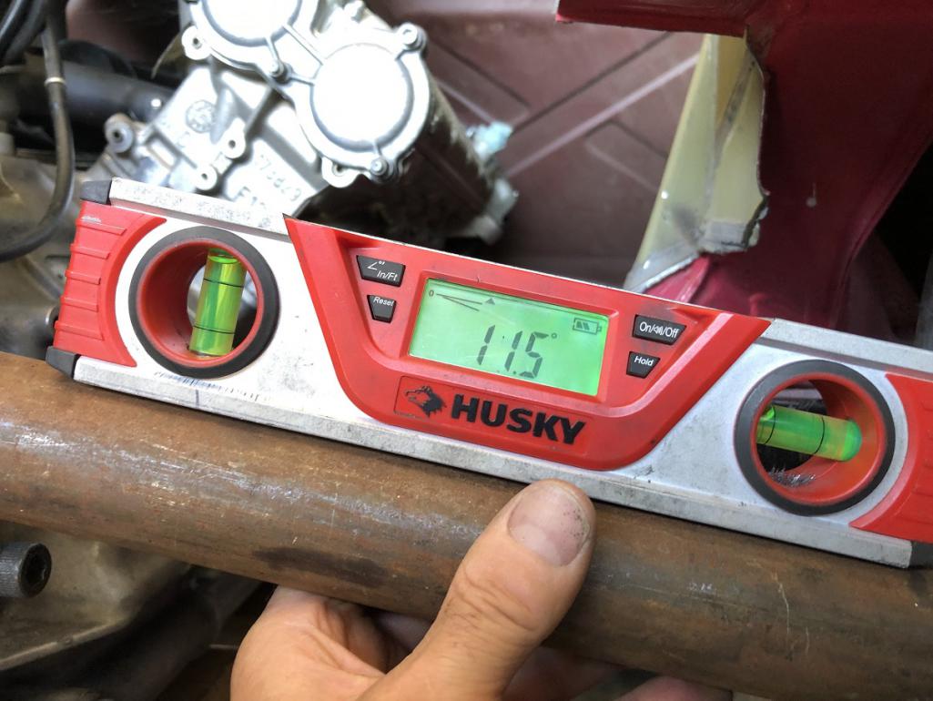
|
| tygaboy |
 Sep 4 2022, 03:08 PM Sep 4 2022, 03:08 PM
Post
#239
|
|
914 Guru      Group: Members Posts: 5,451 Joined: 6-October 15 From: Petaluma, CA Member No.: 19,241 Region Association: Northern California 
|
On a simpler note, the left side, lower rear spreader plate has been completed.
I got a nice fit on this side, too. A bit of grinding and it'll be ready for the transmission mount cross bars! Attached thumbnail(s) 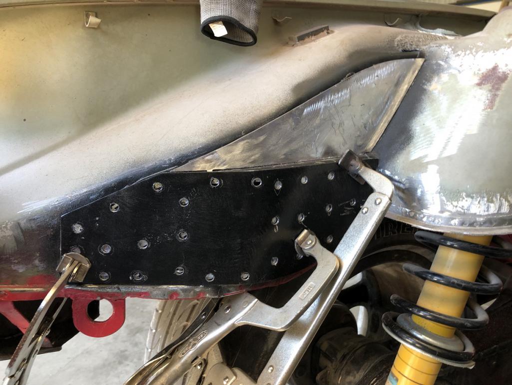 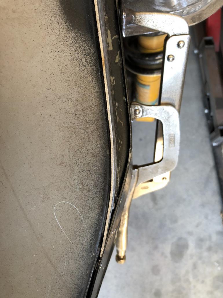 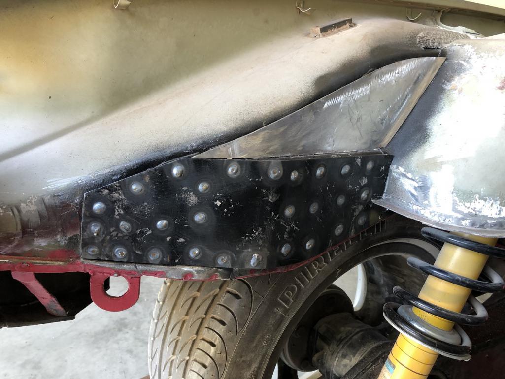
|
| tygaboy |
 Sep 4 2022, 04:16 PM Sep 4 2022, 04:16 PM
Post
#240
|
|
914 Guru      Group: Members Posts: 5,451 Joined: 6-October 15 From: Petaluma, CA Member No.: 19,241 Region Association: Northern California 
|
Transmission mount cross bar locating in process. I have a fair bit of leeway so much of it is down to aesthetics.
That last pic shows the mounting tab sits well under the plane of the top of the bars. Important because that's where the floor of the removable trunk will sit. Attached image(s) 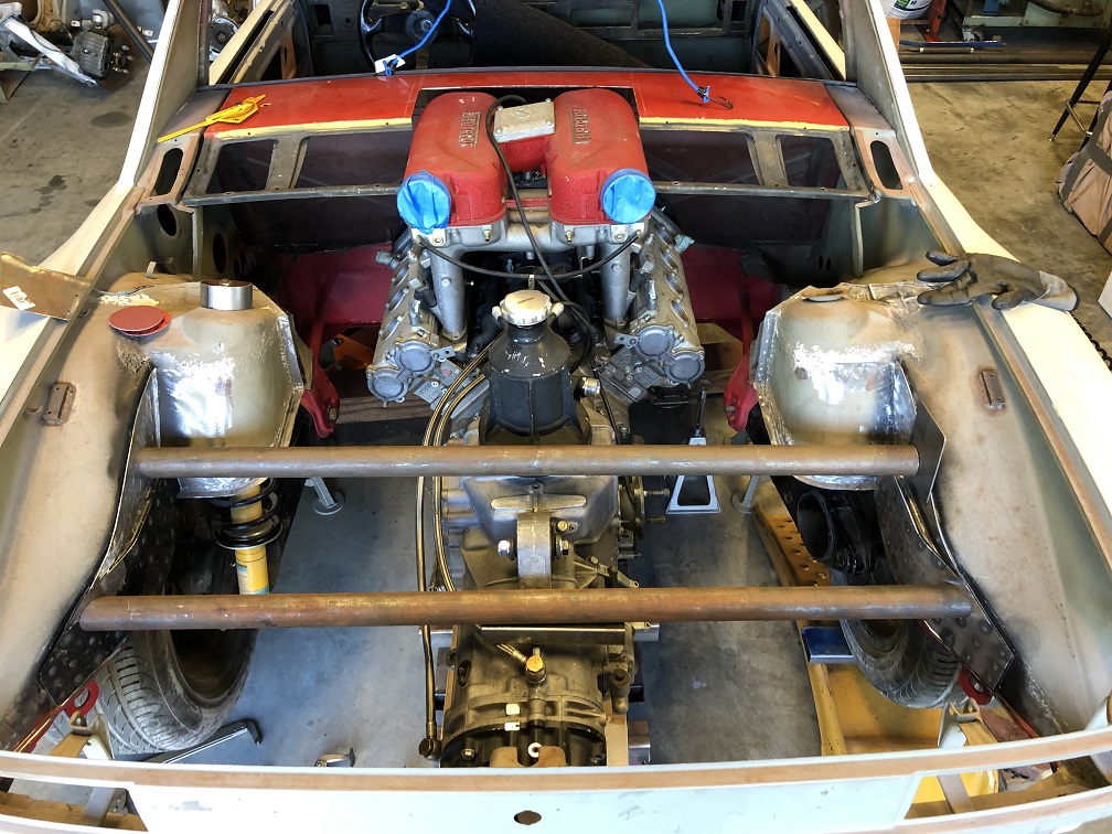 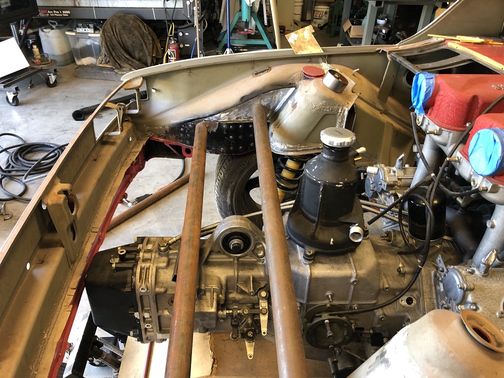 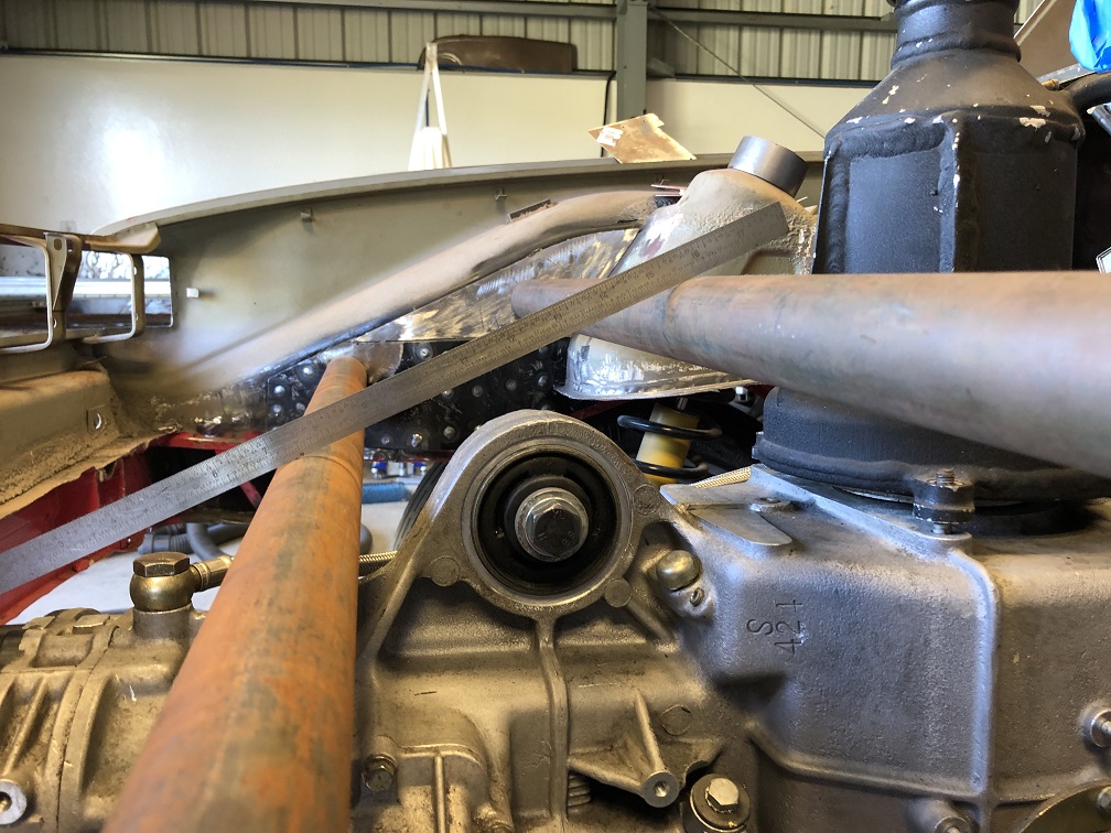
|
  |
3 User(s) are reading this topic (3 Guests and 0 Anonymous Users)
0 Members:

|
Lo-Fi Version | Time is now: 23rd November 2024 - 06:03 AM |
Invision Power Board
v9.1.4 © 2024 IPS, Inc.


