|
|

|
Porsche, and the Porsche crest are registered trademarks of Dr. Ing. h.c. F. Porsche AG.
This site is not affiliated with Porsche in any way. Its only purpose is to provide an online forum for car enthusiasts. All other trademarks are property of their respective owners. |
|
|
  |
| Maltese Falcon |
 Sep 4 2022, 09:07 PM Sep 4 2022, 09:07 PM
Post
#241
|
|
Advanced Member     Group: Members Posts: 4,844 Joined: 14-September 04 From: Mulholland SoCal Member No.: 2,755 Region Association: None  |
Careful what you wish for. I thought it was a super duper thing that the Ferrari transmission output flanges were higher than the Boxster S. Turns out they are really high. Too high? I'm working on figuring out exactly this. Here's a really rough mock up with the drive train at proper-ish height in the chassis and the trailing arm set to approximate ride height. Because of the output flange height, the wheel-side CV will never be higher than the trans output CV; it's all droop, all the time. What I need to work out is: Can a 930 CV (which has a max limit of 28 degrees) stay in range during operation? I'm pretty sure I'll have to add limit straps to stop things drooping too far when I jack the rear wheels off the ground. It may also require lowering the drive train in the chassis and building a rub bar/skid plate. It wouldn't be any worse than doing a dropped floor, in terms of ground clearance. So. Many. Items. To. Work. Out. Leather limit straps were used in the 935s in the past in order to deal with the suspension droop being over the limit for the on-board air jacks to allow for tire changes. Modern days with the introduction of nitrogen filled + adjustable specs (JRZ, Moton, KW, etc.), the internal discs can be internally adjusted to customer specs for any dedicated droop limit. These JRZs out of the box had major rear suspension droop. Cary from ERP suspension came by to measure the JRZ units, took over to their shop for mods and now perfect. 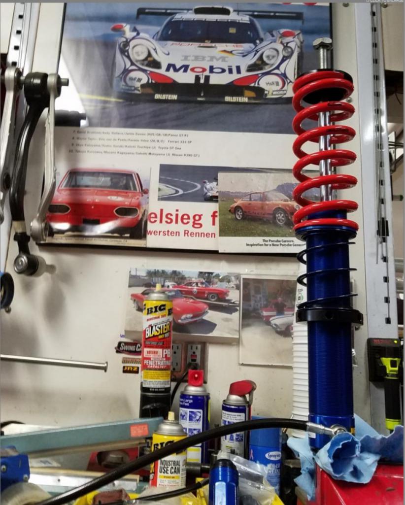 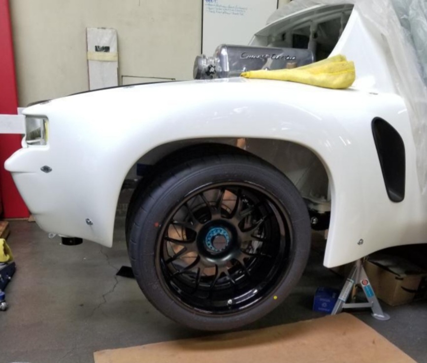 |
| tygaboy |
 Sep 4 2022, 09:20 PM Sep 4 2022, 09:20 PM
Post
#242
|
|
914 Guru      Group: Members Posts: 5,451 Joined: 6-October 15 From: Petaluma, CA Member No.: 19,241 Region Association: Northern California 
|
What I need to work out is: Can a 930 CV (which has a max limit of 28 degrees) stay in range during operation? I'm pretty sure I'll have to add limit straps to stop things drooping too far when I jack the rear wheels off the ground. Leather limit straps were used in the 935s in the past in order to deal with the suspension droop being over the limit for the on-board air jacks to allow for tire changes. Modern days with the introduction of nitrogen filled + adjustable specs (JRZ, Moton, KW, etc.), the internal discs can be internally adjusted to customer specs for any dedicated droop limit. These JRZs out of the box had major rear suspension droop. Cary from ERP suspension came by to measure the JRZ units, took over to their shop for mods and now perfect. @Maltese Falcon - I may need to give you a call to talk details. Thanks for chiming in! |
| stownsen914 |
 Sep 5 2022, 07:16 AM Sep 5 2022, 07:16 AM
Post
#243
|
|
Senior Member    Group: Members Posts: 930 Joined: 3-October 06 From: Ossining, NY Member No.: 6,985 Region Association: None |
I've used bolt-on limiting straps to limit droop, and also plastic disks inside the shocks like Maltese Falcon mentioned to limit droop on different racecars. Either will do the trick.
|
| stownsen914 |
 Sep 5 2022, 07:17 AM Sep 5 2022, 07:17 AM
Post
#244
|
|
Senior Member    Group: Members Posts: 930 Joined: 3-October 06 From: Ossining, NY Member No.: 6,985 Region Association: None |
I've used bolt-on limiting straps to limit droop, and also plastic disks inside the shocks like Maltese Falcon mentioned to limit droop on different racecars. Either will do the trick. As long as you leave 2-3 inches of droop below normal ride height, you're good. |
| tygaboy |
 Sep 5 2022, 12:02 PM Sep 5 2022, 12:02 PM
Post
#245
|
|
914 Guru      Group: Members Posts: 5,451 Joined: 6-October 15 From: Petaluma, CA Member No.: 19,241 Region Association: Northern California 
|
For the trans mount cross bars, it looks like it's back to a revised version of a previous design. Shocking, I know. But there is a bit of a surprise / some style points when you see the overall design.
I also started in on the motor mounts. Many pieces yet to be fabbed but it gets a key item into CAD and proven to fit. Hopefully, the drive train will be mounted in a week or so. Attached image(s) 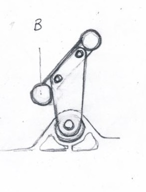 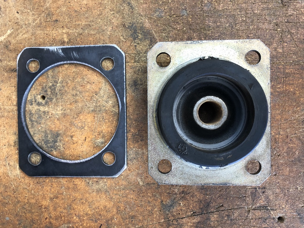 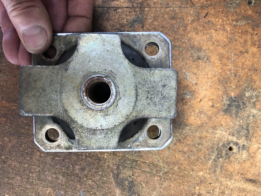
|
| Van B |
 Sep 5 2022, 03:57 PM Sep 5 2022, 03:57 PM
Post
#246
|
|
Senior Member    Group: Members Posts: 1,618 Joined: 20-October 21 From: WR, GA Member No.: 26,011 Region Association: None 
|
That poor mount… oh the abuse it will suffer lol
|
| tygaboy |
 Sep 5 2022, 06:05 PM Sep 5 2022, 06:05 PM
Post
#247
|
|
914 Guru      Group: Members Posts: 5,451 Joined: 6-October 15 From: Petaluma, CA Member No.: 19,241 Region Association: Northern California 
|
With a pretty good idea of the trans mount design, I started in on how to make it as simple as possible to locate the engine mount "landing pads". Rather than deal with taking the drive train in and out 100 times, leveling it each time, etc, etc, etc., the approach is going to be to make a fixture that replicates the locations of the transmission hanger tab and the engine mounts. The drawing shows the basic design. This will be made level to the engine so when it's level, I know the engine will be, too.
Then "all I have to do" is: - Level the car (fore/aft and side-to-side) - BIG IMPORTANT PART: locate the engine fore/aft and up/down and determine the transmission hanger bolt location. Not that hard really... - fab and install the transmission cross members and hanger brackets to support the above location. The trans tab is dead center in the car so getting things properly located is reasonably straight forward - bolt the fixture to the trans mount and swing it up until it's level I'll then have the locations in space that represent where the Ferrari mounts need to be. See how easy? (IMG:style_emoticons/default/laugh.gif) Attached thumbnail(s) 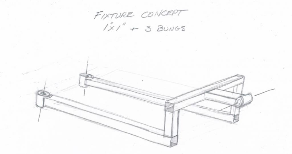
|
| tygaboy |
 Sep 5 2022, 06:24 PM Sep 5 2022, 06:24 PM
Post
#248
|
|
914 Guru      Group: Members Posts: 5,451 Joined: 6-October 15 From: Petaluma, CA Member No.: 19,241 Region Association: Northern California 
|
Then I got it in my head to verify some of the key measurements. I first made up a test piece for the landing pad. This isn't the final outer dimension, it's to validate the hole locations and get a better feel for how much room there will be for fasteners, to determing if I want to have permanent, threaded bungs as part of the part, etc.
My measurements were fine and it did uncover some info. Not a lot of room for fasteners with the holes that close to the rubber. Also, this mount is pretty soft. Surprising how much it can be moved by hand. I'll check with the Ferrari crowd but I think I'll play it safe and get new ones. Also, notice that the upper "X" plate isn't clocked straight to the lower plate. When I looked online at the new part, they seemed in-line with each other. More info that you'll never use is that these mounts use 2 collared spacers, which means that if you're not careful when tightening the main mount bolt, you can twist the rubber and clamp it "out of alignment". That can't help with longevtiy of the mount... More stuff to think about during final assembly. See Post #245 above for pics. |
| tygaboy |
 Sep 5 2022, 06:33 PM Sep 5 2022, 06:33 PM
Post
#249
|
|
914 Guru      Group: Members Posts: 5,451 Joined: 6-October 15 From: Petaluma, CA Member No.: 19,241 Region Association: Northern California 
|
Then, to get another measurement I can use for validation during the landing pad fab process, I went after getting the distance from engine mount to engine mount.
I removed the mounts from the cast aluminum bosses on the engine, dropped a plumb bob through the bosses and marked the location on the floor. Repeat on the other side, move the engine and measure distance between the dots on the floor. Next I used this distance (561 mm, if anyone needs to make a 360 engine mount (IMG:style_emoticons/default/lol-2.gif) ) and, using that test plate CAD file, I made up what's essentially a "go/no go" gauge. If this bolts to the engine mounts, I know my measurements are a "go". They are! (IMG:style_emoticons/default/cheer.gif) (IMG:style_emoticons/default/aktion035.gif) I may be able to repurpose this for use with the fixture. I plan to start making that tomorrow. Slow progress, but progress nontheless. I'll take it. Attached thumbnail(s) 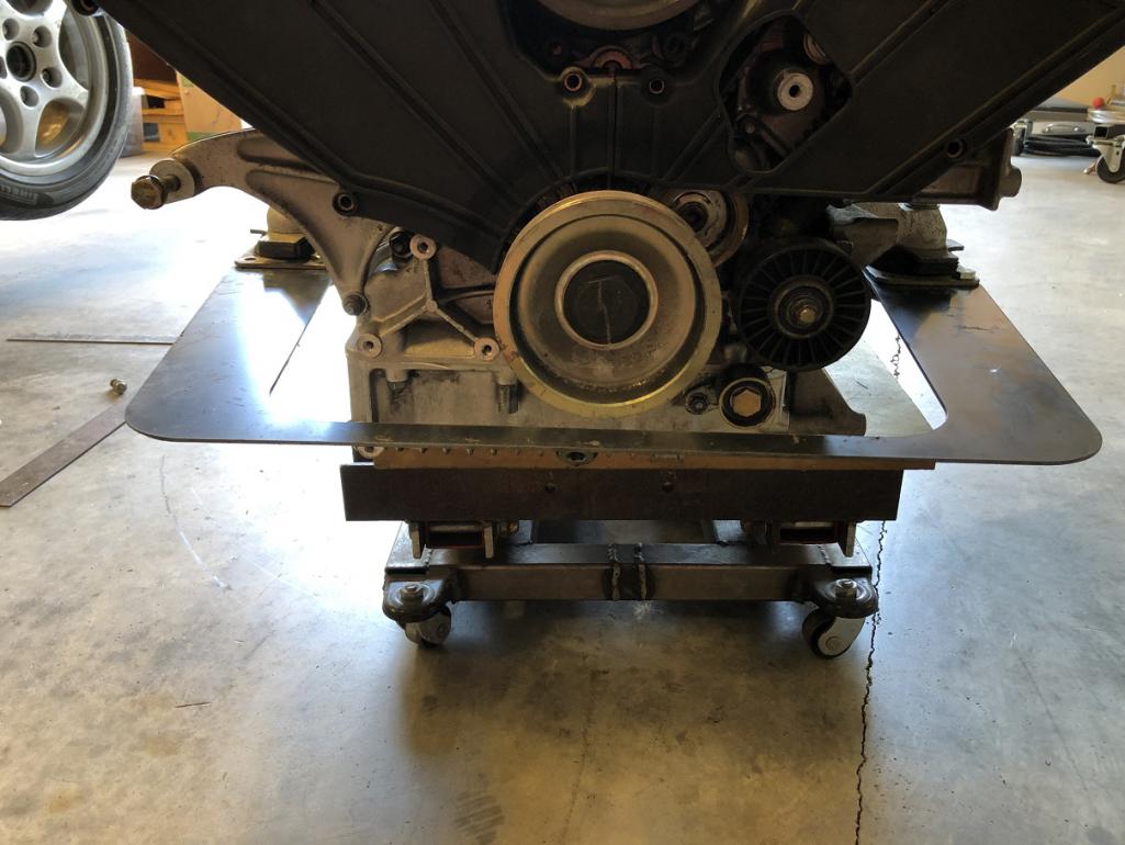 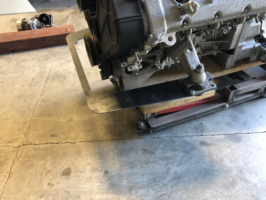
|
| mfennell |
 Sep 6 2022, 08:32 AM Sep 6 2022, 08:32 AM
Post
#250
|
|
Newbie  Group: Members Posts: 1 Joined: 6-September 22 From: NJ Member No.: 26,827 Region Association: None |
I hope you don't mind me registering to throw in a few cents of Ferrari info. Saw your build on grassrootsmotorsports.
Yes to replacing those engine mounts. They are not great. I helped my friend replace the ones in his 11k mile F430. They fell apart once the weight of the engine was off them! Also the trans mount. Unless it still has the new-trans-mount smell, you should replace it. Mike |
| tygaboy |
 Sep 6 2022, 05:40 PM Sep 6 2022, 05:40 PM
Post
#251
|
|
914 Guru      Group: Members Posts: 5,451 Joined: 6-October 15 From: Petaluma, CA Member No.: 19,241 Region Association: Northern California 
|
I hope you don't mind me registering to throw in a few cents of Ferrari info. Saw your build on grassrootsmotorsports. Yes to replacing those engine mounts. They are not great. I helped my friend replace the ones in his 11k mile F430. They fell apart once the weight of the engine was off them! Also the trans mount. Unless it still has the new-trans-mount smell, you should replace it. Mike @mfennell Mike - Are you kidding? I'll take all the help I can get! Please don't ever hesitate to toss information, suggestions or constructive critisism my way. |
| tygaboy |
 Sep 6 2022, 05:50 PM Sep 6 2022, 05:50 PM
Post
#252
|
|
914 Guru      Group: Members Posts: 5,451 Joined: 6-October 15 From: Petaluma, CA Member No.: 19,241 Region Association: Northern California 
|
It was about 105 degrees in the Red Barn today but I can take the heat and I'm staying in this kitchen!
As you know, I like to make a part and see it in real life before I know if I like it. Today was playing with a couple different designs/layouts for the transmission cross bars. In both of these, there will be a box that connects the bars and bosses in that box will have aluminum plates that drop down and pick up the transmission tab. I think I like the one that has the bars in front of the trans tab. This would require plates that cantilever off the back. If you look back at the Ferrari mount, it has that same sort of design so I think it'll work just fine. Still TBD but it's nice to see things "in the metal". And if I get lucky, the bend in that top tube will match the V of the engine! Talk about style points! (IMG:style_emoticons/default/wub.gif) Note too, that these bars will form the basic shape of the removable trunk so if you squint real hard, you can see how cool that shape is going to be. Attached thumbnail(s) 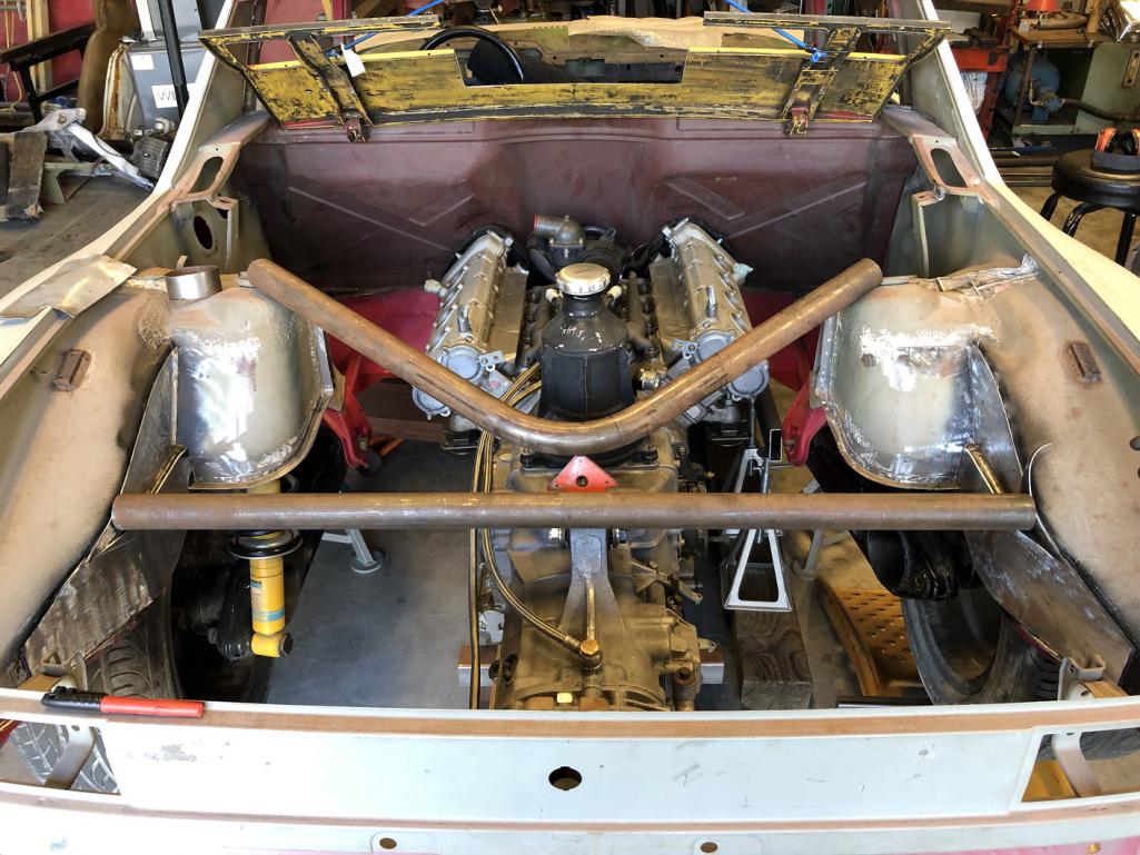 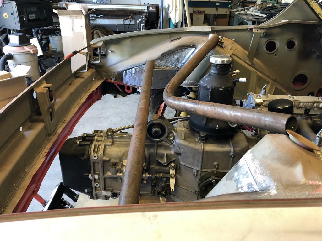 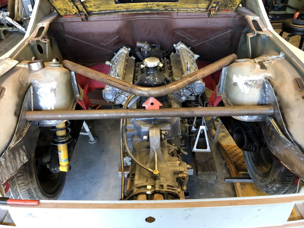 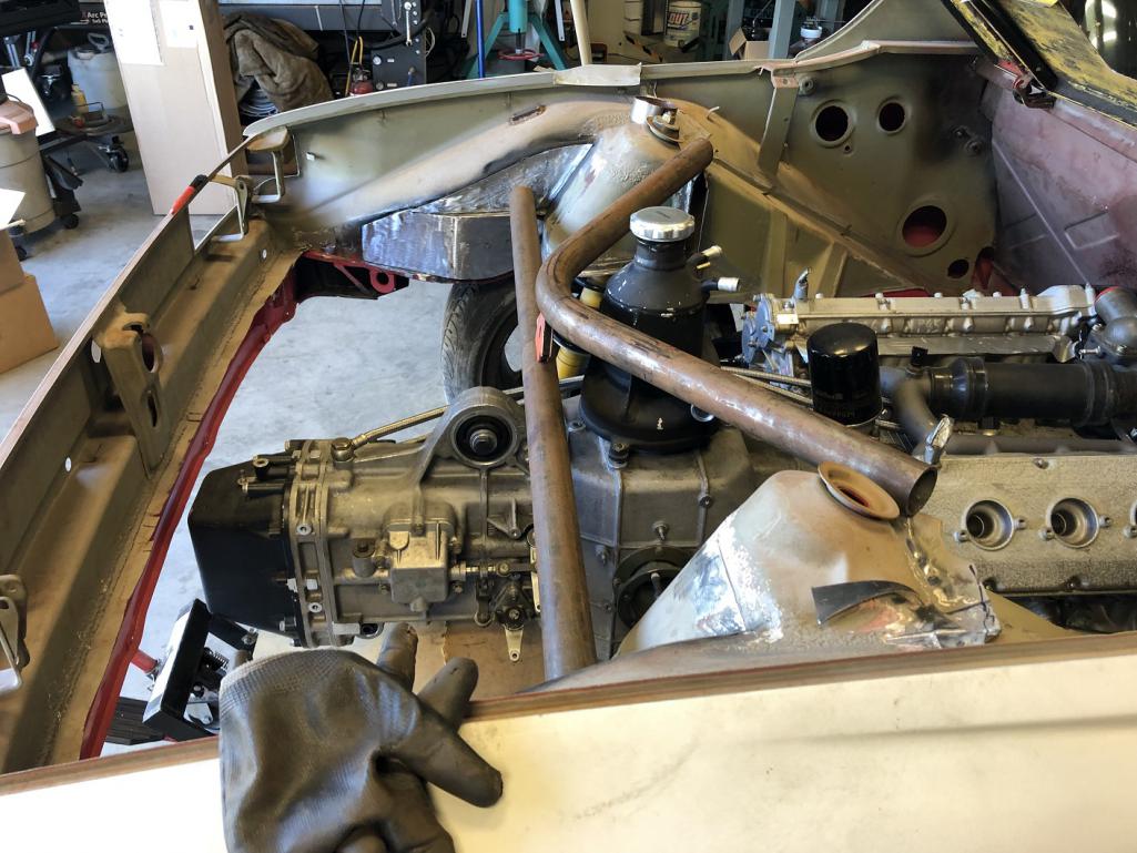
|
| tygaboy |
 Sep 6 2022, 07:01 PM Sep 6 2022, 07:01 PM
Post
#253
|
|
914 Guru      Group: Members Posts: 5,451 Joined: 6-October 15 From: Petaluma, CA Member No.: 19,241 Region Association: Northern California 
|
On 3rd thought, maybe it's this version. Better support for the hanger plates and a nice match to the engine V. The tape approximates the box that'll house the hanger mount bosses.
Attached thumbnail(s) 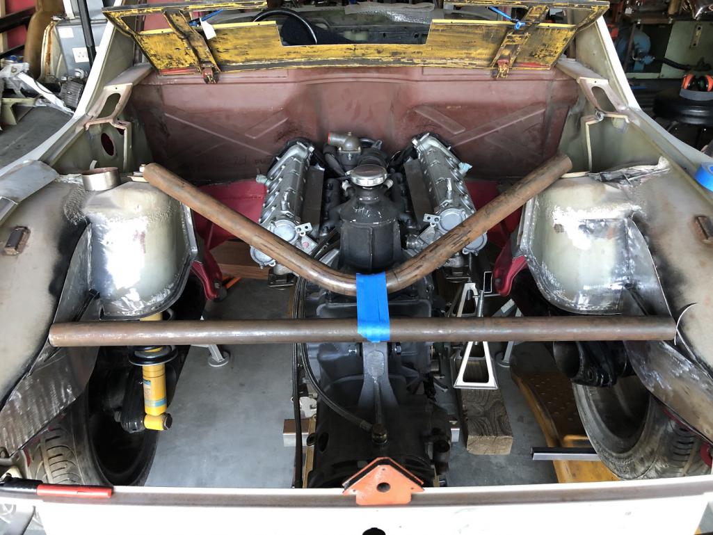 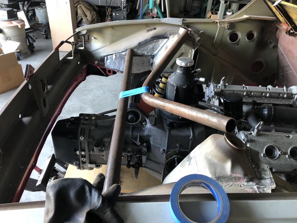
|
| Front yard mechanic |
 Sep 6 2022, 07:42 PM Sep 6 2022, 07:42 PM
Post
#254
|
|
Senior Member    Group: Members Posts: 1,227 Joined: 23-July 15 From: New Mexico Member No.: 18,984 Region Association: None 
|
I’m liking her curvature
|
| horizontally-opposed |
 Sep 6 2022, 09:09 PM Sep 6 2022, 09:09 PM
Post
#255
|
|
Advanced Member     Group: Members Posts: 3,445 Joined: 12-May 04 From: San Francisco Member No.: 2,058 Region Association: None 
|
I’m liking her curvature Ha, curious to see straight runs to a pointed V—to each their own. (IMG:style_emoticons/default/beerchug.gif) Curious: Which setup would be stronger? Trying to think of OE setups, whether Ferrari or Porsche or McLaren etc? If you went with straight pipes, and they are stronger, could the "V" pipes be thinner—or even removable for service? Have to imagine either are going to be pretty with Chris' fab work. |
| Retroracer |
 Sep 6 2022, 11:13 PM Sep 6 2022, 11:13 PM
Post
#256
|
|
Senior Member    Group: Members Posts: 621 Joined: 7-July 13 From: Bend OR Member No.: 16,100 Region Association: Pacific Northwest 
|
I like the lines /flow. Looks like it'll do the job; obvi you need to think about clearance / placement for airboxes, intake piping, filters, etc. Keep the posts coming!
- Tony |
| steuspeed |
 Sep 6 2022, 11:50 PM Sep 6 2022, 11:50 PM
Post
#257
|
|
Senior Member    Group: Members Posts: 1,008 Joined: 12-July 11 From: Portland, Oregon Member No.: 13,308 Region Association: Pacific Northwest |
Shock tower bracing seems like a 2 for 1 here.
|
| ClayPerrine |
 Sep 7 2022, 06:04 AM Sep 7 2022, 06:04 AM
Post
#258
|
|
Life's been good to me so far.....                Group: Admin Posts: 15,901 Joined: 11-September 03 From: Hurst, TX. Member No.: 1,143 Region Association: NineFourteenerVille 
|
I would use the straight crossbar.
Any bends in a pipe make is somewhat weaker and prone to more distortion at the bend in the pipe. Function over form. Clay |
| rick 918-S |
 Sep 7 2022, 06:15 AM Sep 7 2022, 06:15 AM
Post
#259
|
|
Hey nice rack! -Celette                Group: Members Posts: 20,783 Joined: 30-December 02 From: Now in Superior WI Member No.: 43 Region Association: Northstar Region 

|
Nice build (IMG:style_emoticons/default/sawzall-smiley.gif) (IMG:style_emoticons/default/smash.gif) (IMG:style_emoticons/default/welder.gif)
My transaxle is moved back (rearward) 2" and I do not have axle issues with stock axles. Except when I broke a worn out CV dropping the clutch. (IMG:style_emoticons/default/slap.gif) (IMG:style_emoticons/default/assimilate.gif) http://www.914world.com/bbs2/index.php?sho...ic=7725&hl= |
| ClayPerrine |
 Sep 7 2022, 06:31 AM Sep 7 2022, 06:31 AM
Post
#260
|
|
Life's been good to me so far.....                Group: Admin Posts: 15,901 Joined: 11-September 03 From: Hurst, TX. Member No.: 1,143 Region Association: NineFourteenerVille 
|
 |
  |
1 User(s) are reading this topic (1 Guests and 0 Anonymous Users)
0 Members:

|
Lo-Fi Version | Time is now: 23rd November 2024 - 08:23 AM |
Invision Power Board
v9.1.4 © 2024 IPS, Inc.


