|
|

|
Porsche, and the Porsche crest are registered trademarks of Dr. Ing. h.c. F. Porsche AG.
This site is not affiliated with Porsche in any way. Its only purpose is to provide an online forum for car enthusiasts. All other trademarks are property of their respective owners. |
|
|
  |
| tygaboy |
 Sep 7 2022, 08:11 AM Sep 7 2022, 08:11 AM
Post
#261
|
|
914 Guru      Group: Members Posts: 5,451 Joined: 6-October 15 From: Petaluma, CA Member No.: 19,241 Region Association: Northern California 
|
I’m liking her curvature Ha, curious to see straight runs to a pointed V—to each their own. (IMG:style_emoticons/default/beerchug.gif) Curious: Which setup would be stronger? Trying to think of OE setups, whether Ferrari or Porsche or McLaren etc? If you went with straight pipes, and they are stronger, could the "V" pipes be thinner—or even removable for service? Have to imagine either are going to be pretty with Chris' fab work. @horizontally-opposed Pete - You know me: I need to play around with various options. Good call/great minds on the tube diameter. That's 1.75" in the pics and I'm leaning toward 1.5". A bit better scale for the car - and this engine. It's tiny compared to the LS, intake aside. And note that in my LS car, the main trans cross bar is 1.75" and everything else in the car is 1.5". Another thing to consider is that I used a 6" radius die on that bend. General race cage rules call out a minimum bend radius of 3x tube diameter so I could go as small as 4.5" radius, assuming 1.5". That would tighten up the look of that area. More noodling, for sure. (IMG:style_emoticons/default/idea.gif) Keep the input coming! |
| tygaboy |
 Sep 7 2022, 08:22 AM Sep 7 2022, 08:22 AM
Post
#262
|
|
914 Guru      Group: Members Posts: 5,451 Joined: 6-October 15 From: Petaluma, CA Member No.: 19,241 Region Association: Northern California 
|
I would use the straight crossbar. Any bends in a pipe make is somewhat weaker and prone to more distortion at the bend in the pipe. Function over form. Clay @ClayPerrine Clay - Function over form... Have you met me? (IMG:style_emoticons/default/lol-2.gif) But seriously. One of the designs uses a bent tube, with the bend set vertically, just behind the trans mount. This tube would see forces trying to "unbend" it, make it longer and forcing the chassis wider where its welded at the inner fender. Think "arched doorway". That vs a straight tube where forces are trying to shorten it and pull the fender weldment location inward. Bending moments, bending moments... In the end, whichever design wins out, it'll be overbuilt given the car's use case. We want Function AND Form! (IMG:style_emoticons/default/aktion035.gif) |
| horizontally-opposed |
 Sep 7 2022, 10:56 AM Sep 7 2022, 10:56 AM
Post
#263
|
|
Advanced Member     Group: Members Posts: 3,445 Joined: 12-May 04 From: San Francisco Member No.: 2,058 Region Association: None 
|
Pete - You know me: I need to play around with various options. Good call/great minds on the tube diameter. That's 1.75" in the pics and I'm leaning toward 1.5". A bit better scale for the car - and this engine. It's tiny compared to the LS, intake aside. And note that in my LS car, the main trans cross bar is 1.75" and everything else in the car is 1.5". Another thing to consider is that I used a 6" radius die on that bend. General race cage rules call out a minimum bend radius of 3x tube diameter so I could go as small as 4.5" radius, assuming 1.5". That would tighten up the look of that area. More noodling, for sure. (IMG:style_emoticons/default/idea.gif) Keep the input coming! Ooh, good point re: scale of engine—and now consider the scale of the torque between these V8s, and how it comes in. Normally aspirated Ferrari V8s are a little like normally aspirated flat sixes—not exactly torque rich and what is there is at higher rpm. Tubes might even be able to slighter still... |
| tygaboy |
 Sep 7 2022, 01:59 PM Sep 7 2022, 01:59 PM
Post
#264
|
|
914 Guru      Group: Members Posts: 5,451 Joined: 6-October 15 From: Petaluma, CA Member No.: 19,241 Region Association: Northern California 
|
Ooh, good point re: scale of engine—and now consider the scale of the torque between these V8s, and how it comes in. Normally aspirated Ferrari V8s are a little like normally aspirated flat sixes—not exactly torque rich and what is there is at higher rpm. Tubes might even be able to slighter still... @horizontally-opposed Pete - On the torque thing: yep, exactly! My LS is something like 460 lb/ft and the Ferrari is 275. Easier on everything. On the slighter tubes: I follow the SCCA/NASA tech rules and for a car this weight, the spec is nothing smaller than 1.5" .095 wall. So that's what it's getting. Speaking of which, here we go! |
| tygaboy |
 Sep 7 2022, 02:16 PM Sep 7 2022, 02:16 PM
Post
#265
|
|
914 Guru      Group: Members Posts: 5,451 Joined: 6-October 15 From: Petaluma, CA Member No.: 19,241 Region Association: Northern California 
|
Here's some stuff for those interested in fab tips and tricks. Well, at least how I do this particular sort of thing:
The rear cross bar ends have to be cut at an angle. I measured the angle with a large protractor and got 25 degrees. The first cut is easy enough - just set the cold saw angle and cut it. The 2nd cut is the money cut in that it will set the length AND the angle has to be clocked so it's a mirror to the first one. First, the length: I determined where I wanted the tube to positioned in the chassis and measured between the chassis locations where the rear edge of the bar would land. Since the chassis is getting wider the farther back things go, this is the "long edge" of the tube. Being sure to have the tape measure at the tip (long part) of the first angle cut, I mark the measured distance on the tube then carefully spin the tube so I have that mark all the way around it. Then I position the saw's adjustable jaw to serve as a guide for the blade and position the tube with the mark at the edge of that jaw. That's what's shown in the pics. That last one is from under the saw head with the blade set on the tube, just so I can check things are where I want them. Of course, if you ever mark to cut stuff, you have to play the game of "do I leave the line or cut on the line?" Whatever works for you, just plan, mark and position things accordingly! Attached image(s) 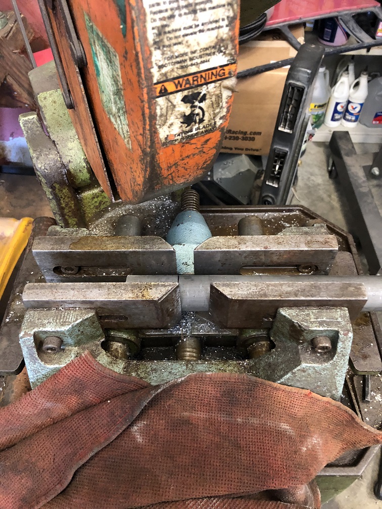 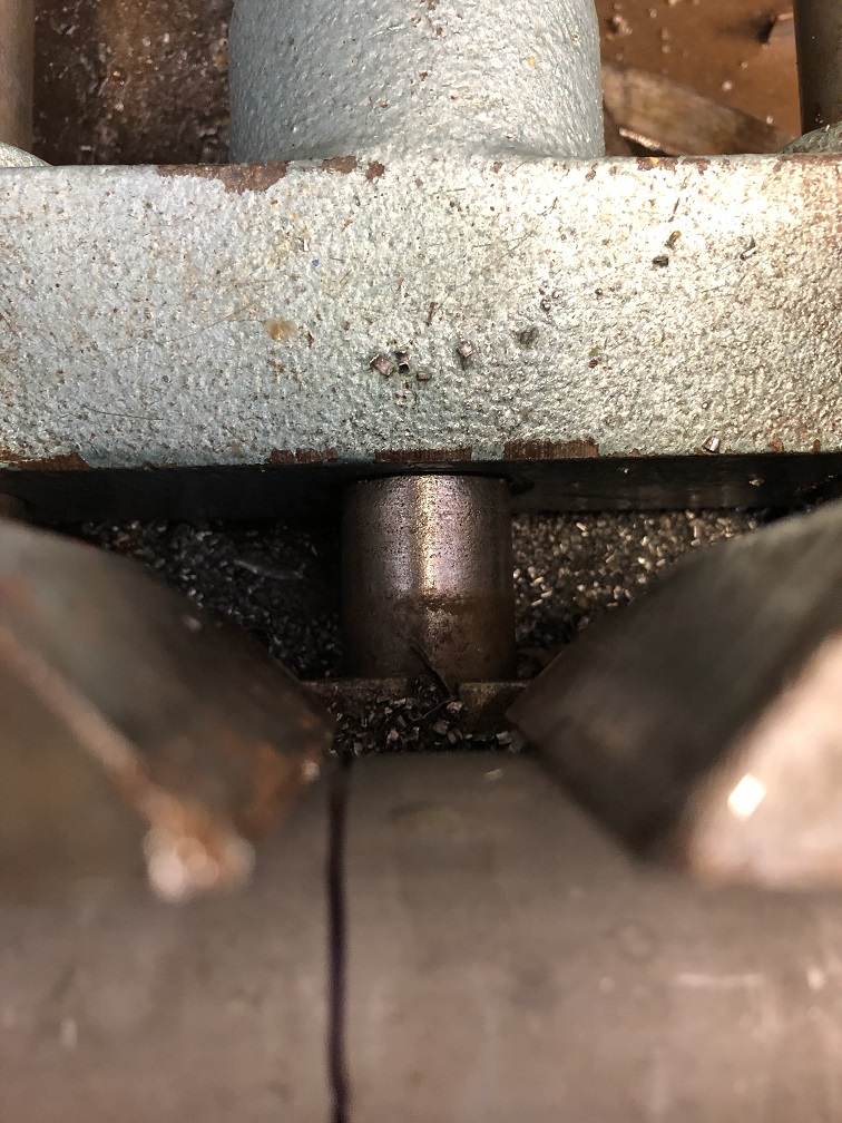 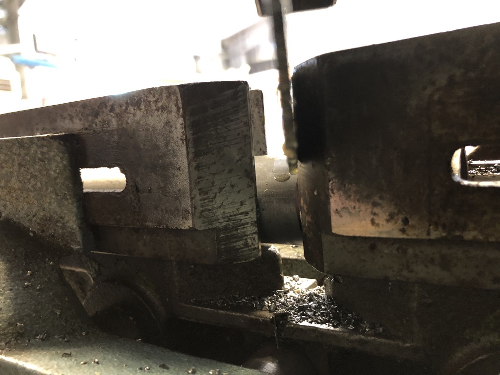
|
| tygaboy |
 Sep 7 2022, 02:22 PM Sep 7 2022, 02:22 PM
Post
#266
|
|
914 Guru      Group: Members Posts: 5,451 Joined: 6-October 15 From: Petaluma, CA Member No.: 19,241 Region Association: Northern California 
|
The next step is the clocking of the cut:
Hold a digital level fast to the face of the first cut. Simply rotate the tube until the level shows 0.0 degrees and you know the faces will be aligned! Simple, no? DO BE CAREFUL that you have the tube oriented in the saw so the cuts will be in the proper orientation else you'll have parallel angled ends not mirrored angled ends!!! I didn't make that mistake on this tube but... Ask me how I know. (IMG:style_emoticons/default/headbang.gif) Attached image(s) 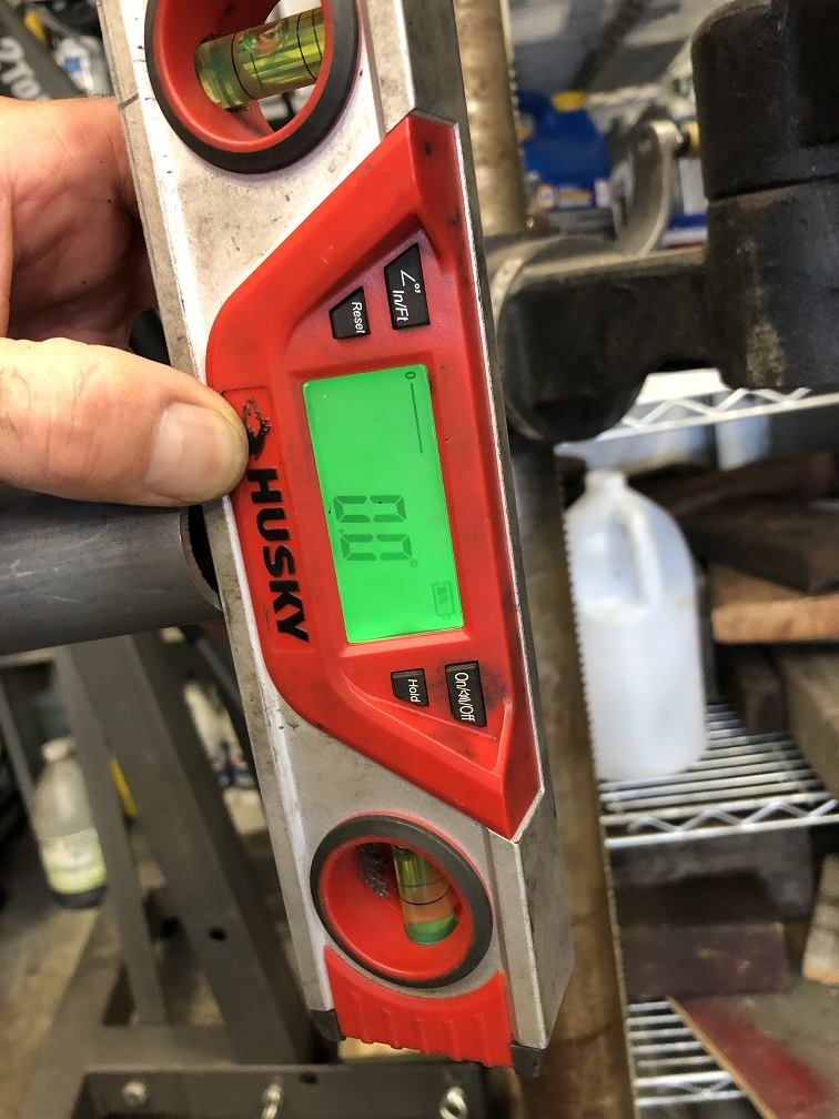 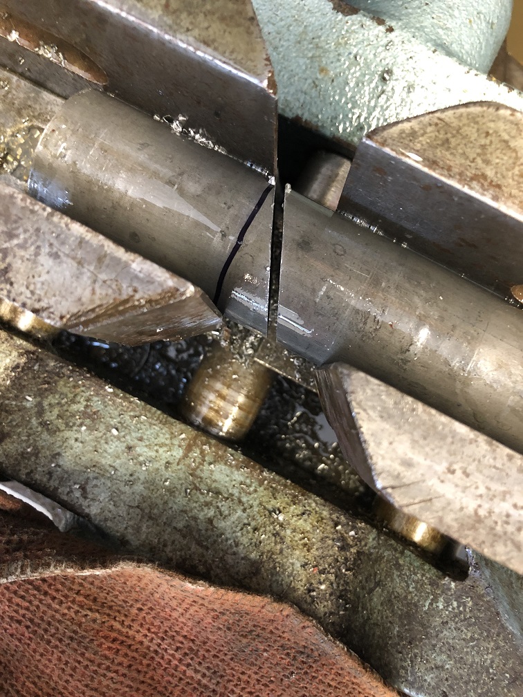
|
| tygaboy |
 Sep 7 2022, 02:23 PM Sep 7 2022, 02:23 PM
Post
#267
|
|
914 Guru      Group: Members Posts: 5,451 Joined: 6-October 15 From: Petaluma, CA Member No.: 19,241 Region Association: Northern California 
|
BAM! I love it when a plan comes together! (IMG:style_emoticons/default/sawzall-smiley.gif) (IMG:style_emoticons/default/smilie_pokal.gif)
Attached image(s) 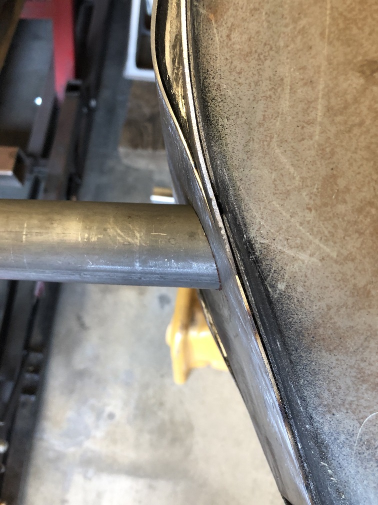
|
| tygaboy |
 Sep 7 2022, 04:54 PM Sep 7 2022, 04:54 PM
Post
#268
|
|
914 Guru      Group: Members Posts: 5,451 Joined: 6-October 15 From: Petaluma, CA Member No.: 19,241 Region Association: Northern California 
|
With the tubes (essentially) located, I went after a proof-of-concept hanger. This is how I do things: prove that the measurements are correct with something simple, adjust as needed until it's what it needs to be then make it "for real".
In this case, the for real pieces will start as 1x3 tube that'll get pie cut and welded to pretty much replicate this shape. And the hole will be replaced with a steel boss. It'll be plenty strong and should look pretty neat, too. And that gap at the back, between the bracket and the rear tube? That's due to the fact that the jack contraption I use doesn't hold the drive train perfectly vertical and that slight tip is causing things to not quite fit. Plus, that tube is trying to fall out of position and is sorta being held in place by that piece of scrap there behind it. Hey, I do what I have to... I also may need to trim the rear tube to get it into its happy place - it has to end up flush to the chassis on both sides and smack in the notches of the final hanger brackets. The good news is that I can move the drive train fore/aft a little, if needed, with no risk of anything colliding. I'm calling this a pretty productive day. Attached thumbnail(s) 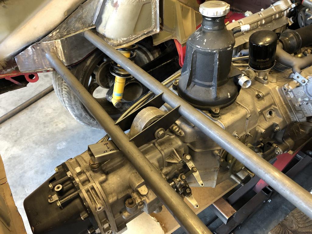 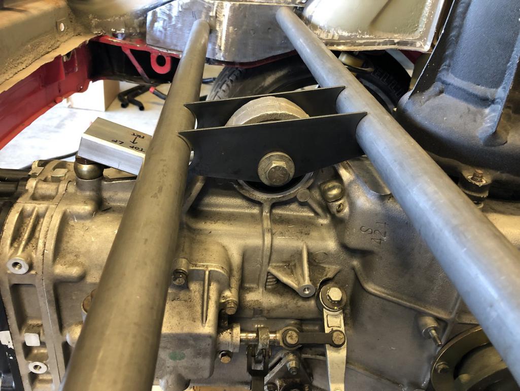
|
| tygaboy |
 Sep 7 2022, 05:10 PM Sep 7 2022, 05:10 PM
Post
#269
|
|
914 Guru      Group: Members Posts: 5,451 Joined: 6-October 15 From: Petaluma, CA Member No.: 19,241 Region Association: Northern California 
|
Probably should have started with this: Here's the final design I landed on, exact cross tube location aside. Pardon my MS Paint hackery.
It's simple and strong, leaves room for a reasonably sized trunk and, most importantly, gives @horizontally-opposed Pete his straight V! (IMG:style_emoticons/default/laugh.gif) The things I do for you guys... Attached image(s) 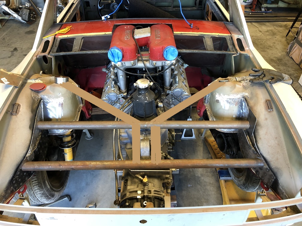
|
| Van B |
 Sep 7 2022, 08:41 PM Sep 7 2022, 08:41 PM
Post
#270
|
|
Senior Member    Group: Members Posts: 1,618 Joined: 20-October 21 From: WR, GA Member No.: 26,011 Region Association: None 
|
I appreciate the rust colored brush lines lol… it shows a solid effort (IMG:style_emoticons/default/lol-2.gif)
Personally though, I think it’s too much for the single point transmission mount. Consider the 996/997 cars, a simple hanger is all you need. The engine mounts are what stabilize the engine from torque twist. |
| Shivers |
 Sep 7 2022, 08:41 PM Sep 7 2022, 08:41 PM
Post
#271
|
|
Senior Member     Group: Members Posts: 2,780 Joined: 19-October 20 From: La Quinta, CA Member No.: 24,781 Region Association: Southern California |
Cool
|
| tygaboy |
 Sep 7 2022, 09:04 PM Sep 7 2022, 09:04 PM
Post
#272
|
|
914 Guru      Group: Members Posts: 5,451 Joined: 6-October 15 From: Petaluma, CA Member No.: 19,241 Region Association: Northern California 
|
I appreciate the rust colored brush lines lol… it shows a solid effort (IMG:style_emoticons/default/lol-2.gif) Personally though, I think it’s too much for the single point transmission mount. Consider the 996/997 cars, a simple hanger is all you need. The engine mounts are what stabilize the engine from torque twist. @Van B - I appreciate the input. I've looked pretty closely at the Ferrari mounting system as used in the 360 chassis, have had my hands on all the mounts and talked in detail about all this with a friend who has a 360 street car and a 360 Challenge car. I'll simply say that this isn't as straight forward as it looks. For example, what I haven't pointed out is the 4th mount/bracket. This bolts to a small tab on the underside of the trans and to a yet-to-be-worked-out "lower cross bar". I don't mean to come across as defensive, just that there's more going on with all this than it might otherwise appear. Plus, I'm a fan of over-building important structural areas. Keep the cards and letters coming. Attached thumbnail(s) 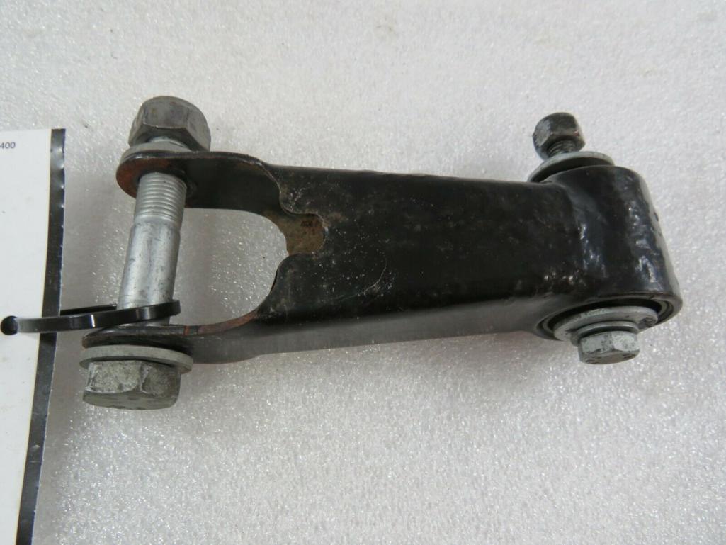
|
| Van B |
 Sep 7 2022, 09:19 PM Sep 7 2022, 09:19 PM
Post
#273
|
|
Senior Member    Group: Members Posts: 1,618 Joined: 20-October 21 From: WR, GA Member No.: 26,011 Region Association: None 
|
Well, I definitely didn’t mean to infer that your direction is wrong. I just think it’s serious overkill. And a fourth mount means you need even less from the top rubber mount. Your un-gusseted plate attachments will be the weakest joint and even that mock up looks stout as whiskey in a plastic bottle lol!
|
| horizontally-opposed |
 Sep 8 2022, 09:38 AM Sep 8 2022, 09:38 AM
Post
#274
|
|
Advanced Member     Group: Members Posts: 3,445 Joined: 12-May 04 From: San Francisco Member No.: 2,058 Region Association: None 
|
I appreciate the rust colored brush lines lol… it shows a solid effort (IMG:style_emoticons/default/lol-2.gif) ^ Lol! Personally though, I think it’s too much for the single point transmission mount. Consider the 996/997 cars, a simple hanger is all you need. The engine mounts are what stabilize the engine from torque twist. The big double bars also feel like overkill to me—and a bit Chevy truck-ish. Not an engineer, and won't pretend to play one, but tend to agree this is a place to "replicate" the factory setup with a boxed beam (maybe thicker) under your proposed trunk floor and maybe something else befitting your capabilities, but now hidden from view: The world's coolest firewall. Probably a lot stronger, too... Then again, that central mount requires a different approach and maybe this here peanut gallery needs to butt out. (IMG:style_emoticons/default/poke.gif) (IMG:style_emoticons/default/beerchug.gif) |
| ClayPerrine |
 Sep 8 2022, 10:30 AM Sep 8 2022, 10:30 AM
Post
#275
|
|
Life's been good to me so far.....                Group: Admin Posts: 15,901 Joined: 11-September 03 From: Hurst, TX. Member No.: 1,143 Region Association: NineFourteenerVille 
|
If I were doing this, I would not have cut the trunk floor out. I would have cut a small hole in it and made a raised box for the trans mount, adding doublers to the trunk floor where needed. I realize I would have had to cut a relief in the rear wall for the oil tank, but the rest would still be there.
And it would still be able to store the targa top in the trunk. Clay |
| tygaboy |
 Sep 8 2022, 03:53 PM Sep 8 2022, 03:53 PM
Post
#276
|
|
914 Guru      Group: Members Posts: 5,451 Joined: 6-October 15 From: Petaluma, CA Member No.: 19,241 Region Association: Northern California 
|
...Then again, that central mount requires a different approach and maybe this here peanut gallery needs to butt out. (IMG:style_emoticons/default/poke.gif) (IMG:style_emoticons/default/beerchug.gif) @horizontally-opposed Pete - Bring on the Peanuts!! I think I've demonstrated I'm open to input. I listen, noodle, then make up my mind - but may change it later, then again after that! (IMG:style_emoticons/default/wacko.gif) That said, I do think Gallery members need to check with @Retroracer Tony first. Remember with all their input on the hood vents of my LS build, we agreed going forward that Tony would be: Assistant Chairman, Design by Committee, 914world inc. (IMG:style_emoticons/default/av-943.gif) |
| tygaboy |
 Sep 8 2022, 04:57 PM Sep 8 2022, 04:57 PM
Post
#277
|
|
914 Guru      Group: Members Posts: 5,451 Joined: 6-October 15 From: Petaluma, CA Member No.: 19,241 Region Association: Northern California 
|
If I were doing this, I would not have cut the trunk floor out. I would have cut a small hole in it and made a raised box for the trans mount, adding doublers to the trunk floor where needed. I realize I would have had to cut a relief in the rear wall for the oil tank, but the rest would still be there. And it would still be able to store the targa top in the trunk. Clay @ClayPerrine Clay - still looking at designs, including one that may allow the top to fit. |
| tygaboy |
 Sep 8 2022, 05:34 PM Sep 8 2022, 05:34 PM
Post
#278
|
|
914 Guru      Group: Members Posts: 5,451 Joined: 6-October 15 From: Petaluma, CA Member No.: 19,241 Region Association: Northern California 
|
Proving yet again that I'm all ears when it comes to build ideas, the comments from @Van B and @horizontally-opposed got me thinking about other transmission mount designs. I have to admit, while that cross bars design is functional, it really isn't that attractive. And as I already mentioned, I'm after function AND form. So...
This is what happened today. No, it's not final. And I'm not going to attempt to explain what's still planned for the overall design, other than to say, I'm liking it better, so far. It's loads simpler and the beam sets the planes for a couple of the trunk panels. I'm also liking the extended shape of the suspension console that ties to the beam, complete with stampings to match the factory panel. I may extend them all the way along the shape of the spreader plates. TBD. The four holes on each side of the hanger echo the cylinder count - but those may give way to something different... So, as usual for this stage of my approach, still a way to go. Attached thumbnail(s) 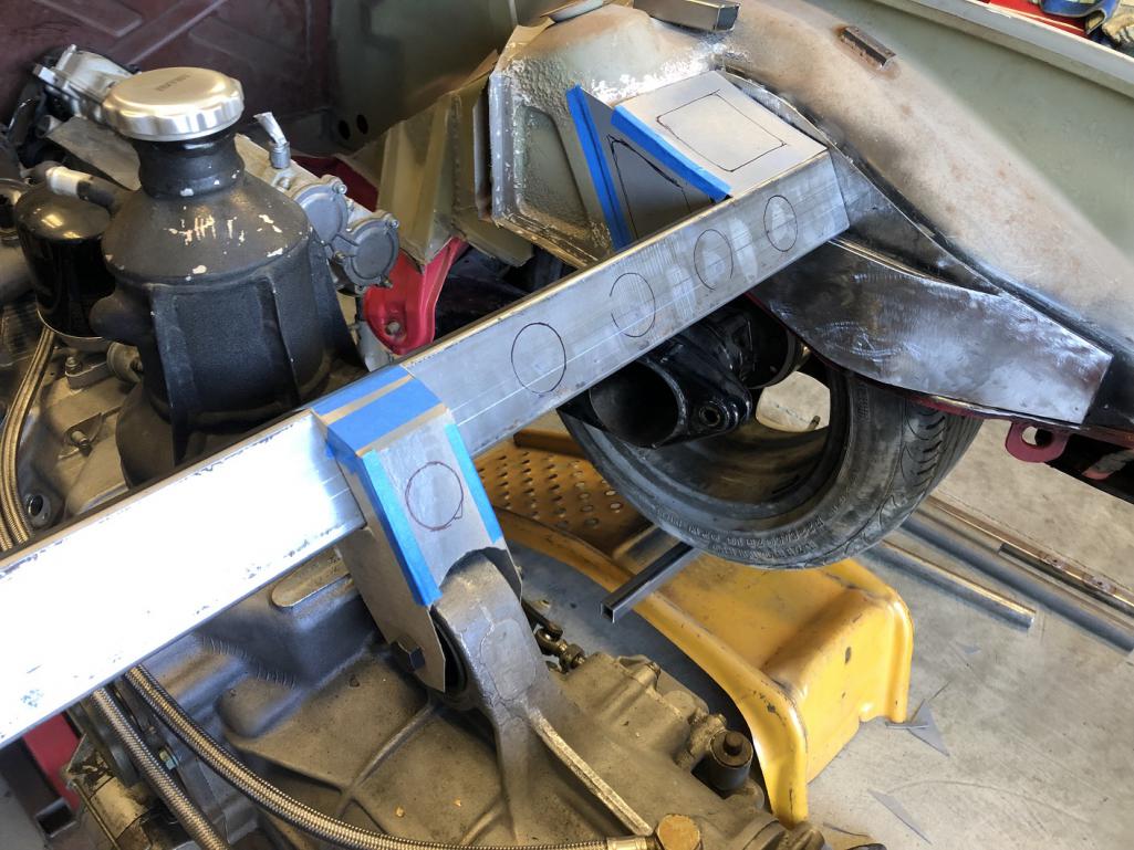
|
| tygaboy |
 Sep 8 2022, 07:36 PM Sep 8 2022, 07:36 PM
Post
#279
|
|
914 Guru      Group: Members Posts: 5,451 Joined: 6-October 15 From: Petaluma, CA Member No.: 19,241 Region Association: Northern California 
|
Then again, that central mount requires a different approach and maybe this here peanut gallery needs to butt out. (IMG:style_emoticons/default/poke.gif) (IMG:style_emoticons/default/beerchug.gif) @horizontally-opposed Pete - Let's agree I'll stop tagging you so often! I did want to address your comment about how this mounting system might be "different". Yep, you're spot on. A few things: That lower transmission mount "link" isn't a solid mount - it's a double pivot. The engine mounts are rather soft and have built in bump stops (!) and the upper trans mount is on the soft side too. Why? I suspect it's because of the flat plane crank, which makes for an inherently, let's say, "less than smooth", engine. It needs to be better, or at least differently, isolated than usual. And that means the drive train actually moves around quite a bit during operation. In trying to understand what Ferrari is up to, it appears it's about allowing the drive train to rotate (a little) around the trans output shafts in reaction to torque, but limiting torsional rotation around the length of the drive train. That lower mount has to allow the trans to rotate around the upper mount, hence the dual pivot, but help that upper mount resist twist. I won't go further than that other than to add that ahead of commenting, folks may want to consider they don't have the same info I do - not that I'm right, just that I have hands and eyes on all these parts and I'm researching a drive train that's a bit different that what we're all used to. Hope everyone understands the intent of this post. And again, please keep the comments and suggestions coming, just note the above. Thanks! |
| Van B |
 Sep 8 2022, 08:23 PM Sep 8 2022, 08:23 PM
Post
#280
|
|
Senior Member    Group: Members Posts: 1,618 Joined: 20-October 21 From: WR, GA Member No.: 26,011 Region Association: None 
|
That is a very clean look! And as long as the cardboard doesn’t get wet, it should hold up beautifully! (IMG:style_emoticons/default/slap.gif)
Seriously though, I see where you’re going here and I think it will really come together well. |
  |
3 User(s) are reading this topic (3 Guests and 0 Anonymous Users)
0 Members:

|
Lo-Fi Version | Time is now: 23rd November 2024 - 09:29 AM |
Invision Power Board
v9.1.4 © 2024 IPS, Inc.


