|
|

|
Porsche, and the Porsche crest are registered trademarks of Dr. Ing. h.c. F. Porsche AG.
This site is not affiliated with Porsche in any way. Its only purpose is to provide an online forum for car enthusiasts. All other trademarks are property of their respective owners. |
|
|
  |
| tygaboy |
 Nov 9 2022, 07:02 PM Nov 9 2022, 07:02 PM
Post
#381
|
|
914 Guru      Group: Members Posts: 5,452 Joined: 6-October 15 From: Petaluma, CA Member No.: 19,241 Region Association: Northern California 
|
Proof of concept of the "center" tab bracket. This is just a first effort based on a card board template and while I got pretty close, I have a couple changes to make to get a better fit. Plus the final version of all the tabs will be cut from 3/16" plate.
The cradle's upper bar will bolt to the outside of this where another tab will be, while the lower bar bolts to the inside of this with its other tab farther inboard. So, yes, the cradle walls will be slightly angled. And that ramp that heads forward under the floor will help establish the front section of the under-drive train skid plate/flat floor. I hope to be able to sneak tunnels on both sides with a difusser at the rear. Attached thumbnail(s) 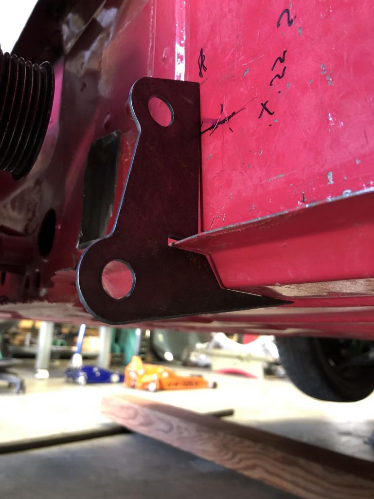
|
| tygaboy |
 Nov 9 2022, 07:05 PM Nov 9 2022, 07:05 PM
Post
#382
|
|
914 Guru      Group: Members Posts: 5,452 Joined: 6-October 15 From: Petaluma, CA Member No.: 19,241 Region Association: Northern California 
|
Here's the CAD rear view of the cradle geometry showing the 1.25" tubing and a 1" OD bung that'll bolt to the above mentioned set of tabs.
Attached image(s) 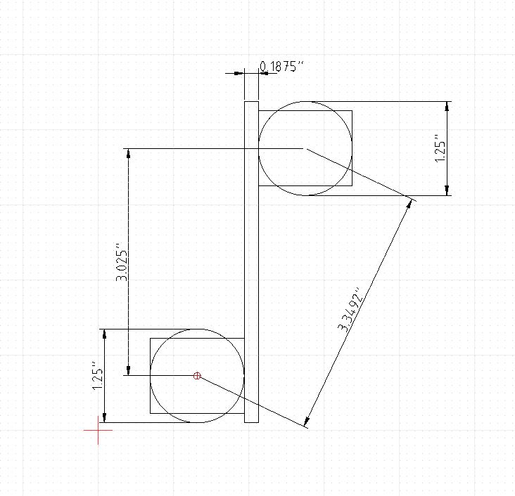
|
| willieg |
 Nov 10 2022, 09:53 AM Nov 10 2022, 09:53 AM
Post
#383
|
|
Member   Group: Members Posts: 138 Joined: 13-August 18 From: Pleasant Hill Member No.: 22,389 Region Association: Northern California 
|
Chris
Seeing yesterday what you are doing with the cradle and bracket, I do have some thoughts. Yes, there is one in every crowd. Cut (2) pieces of 1.25 tubing, 1” long. Fish eye one of the ends of the 1” tubing on both pieces. Weld the fish eye end to the ends of your cradle. Weld a nut onto the other end of the 1” piece of tubing. Run a bolt through your bracket into the nut welded onto the short tubing to secure your cradle the the bracket. BTW: awesome build! |
| Andyrew |
 Nov 11 2022, 05:18 AM Nov 11 2022, 05:18 AM
Post
#384
|
|
Spooling.... Please wait           Group: Members Posts: 13,377 Joined: 20-January 03 From: Riverbank, Ca Member No.: 172 Region Association: Northern California 
|
Proof of concept of the "center" tab bracket. This is just a first effort based on a card board template and while I got pretty close, I have a couple changes to make to get a better fit. Plus the final version of all the tabs will be cut from 3/16" plate. The cradle's upper bar will bolt to the outside of this where another tab will be, while the lower bar bolts to the inside of this with its other tab farther inboard. So, yes, the cradle walls will be slightly angled. And that ramp that heads forward under the floor will help establish the front section of the under-drive train skid plate/flat floor. I hope to be able to sneak tunnels on both sides with a difusser at the rear. Jebus… how tight fitting do you need it Chris? (IMG:style_emoticons/default/smile.gif) I mean it’s just gonna be welded, wouldn’t you want a nice 1/16” gap in there for weld space? Man that looks good! |
| tygaboy |
 Nov 11 2022, 02:29 PM Nov 11 2022, 02:29 PM
Post
#385
|
|
914 Guru      Group: Members Posts: 5,452 Joined: 6-October 15 From: Petaluma, CA Member No.: 19,241 Region Association: Northern California 
|
Jebus… how tight fitting do you need it Chris? (IMG:style_emoticons/default/smile.gif) I mean it’s just gonna be welded, wouldn’t you want a nice 1/16” gap in there for weld space? Man that looks good! @Andyrew Andrew, You've met me, right? (IMG:style_emoticons/default/laugh.gif) As I mentioned after my visit to Singer, my shop mantra is now "Plus or minus less than yesterday!" I'm happy with the latest design's fit. Attached image(s) 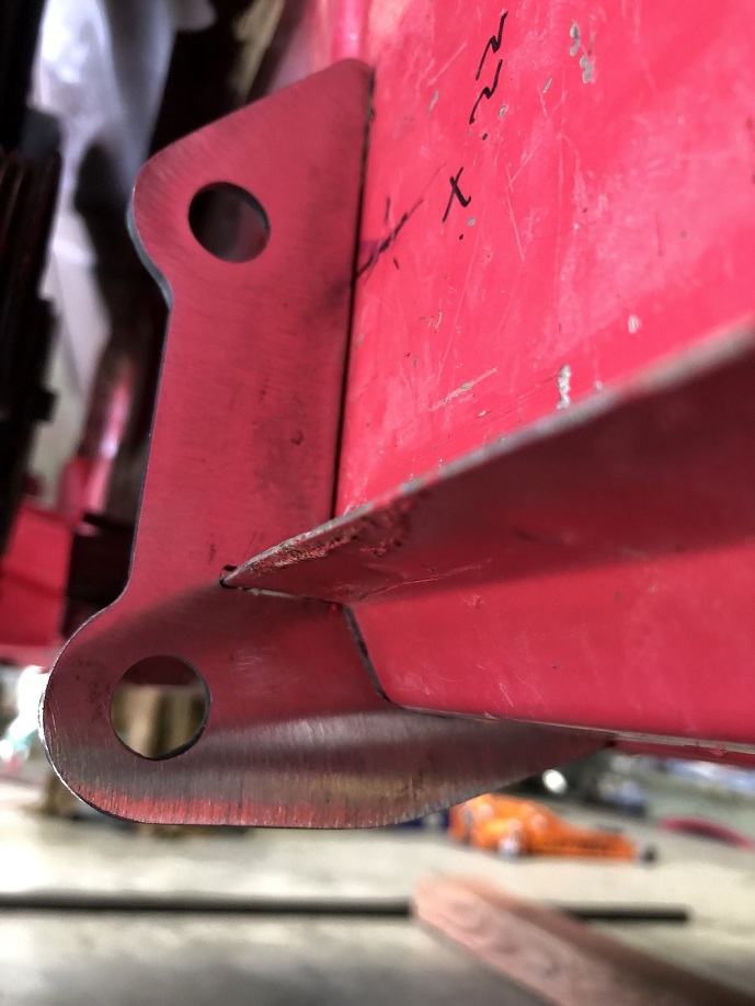
|
| Cairo94507 |
 Nov 11 2022, 03:36 PM Nov 11 2022, 03:36 PM
Post
#386
|
|
Michael           Group: Members Posts: 10,093 Joined: 1-November 08 From: Auburn, CA Member No.: 9,712 Region Association: Northern California 
|
Wow- that is a very nice fit. (IMG:style_emoticons/default/beerchug.gif)
|
| dr914@autoatlanta.com |
 Nov 11 2022, 03:48 PM Nov 11 2022, 03:48 PM
Post
#387
|
|
914 Guru      Group: Members Posts: 8,102 Joined: 3-January 07 From: atlanta georgia Member No.: 7,418 Region Association: None |
|
| tygaboy |
 Nov 11 2022, 05:35 PM Nov 11 2022, 05:35 PM
Post
#388
|
|
914 Guru      Group: Members Posts: 5,452 Joined: 6-October 15 From: Petaluma, CA Member No.: 19,241 Region Association: Northern California 
|
And here are the final parts in 7 ga (3/16"), fitted with approximate width bungs, just to get a look at whereabouts everything will be positioned.
The undersides of the lower cradle tubes will serve as the location for the drive train skid plate. Attached thumbnail(s) 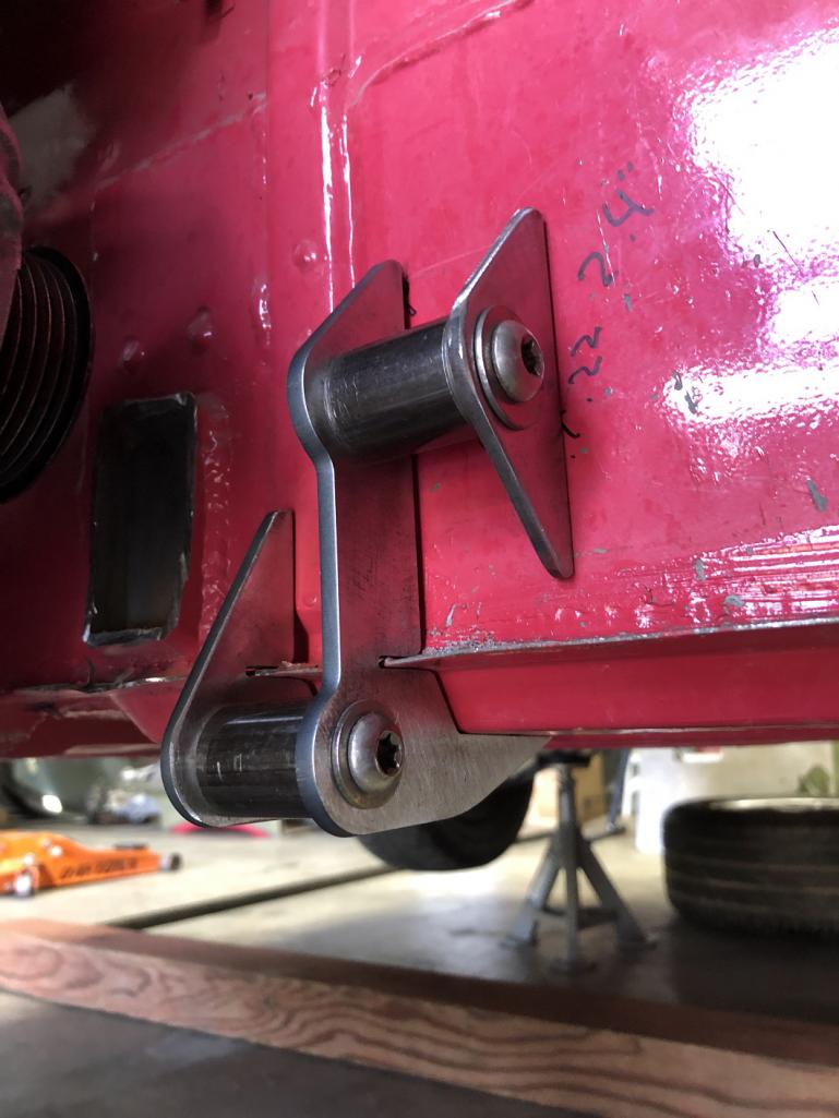 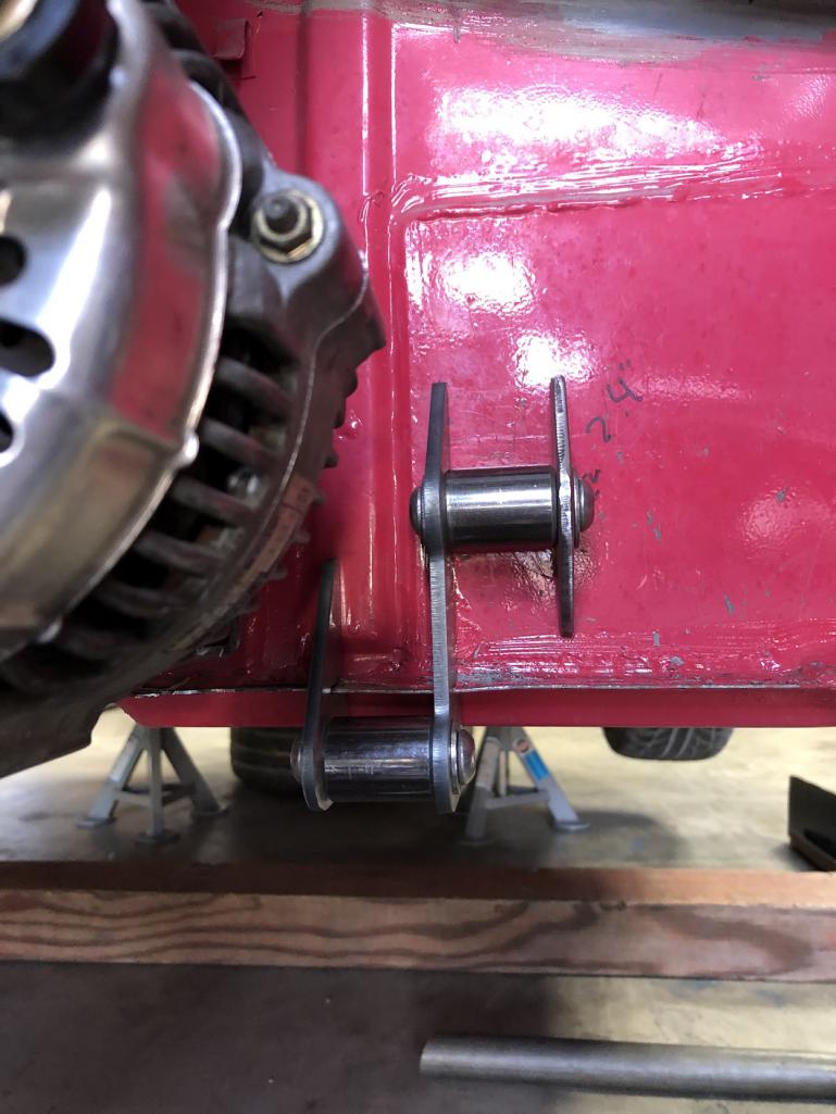
|
| Krieger |
 Nov 11 2022, 06:16 PM Nov 11 2022, 06:16 PM
Post
#389
|
|
Advanced Member     Group: Members Posts: 4,763 Joined: 24-May 04 From: Santa Rosa CA Member No.: 2,104 Region Association: None 
|
Very nice! Now I understand Martin's sketch of the removable mount. Does the third leg of the mount go to the long or is the exhaust the way?
|
| tygaboy |
 Nov 11 2022, 06:34 PM Nov 11 2022, 06:34 PM
Post
#390
|
|
914 Guru      Group: Members Posts: 5,452 Joined: 6-October 15 From: Petaluma, CA Member No.: 19,241 Region Association: Northern California 
|
Very nice! Now I understand Martin's sketch of the removable mount. Does the third leg of the mount go to the long or is the exhaust the way? @Krieger - Andy, Martin's latest sketch was close but changes were made, based on real dimensions. So at this point, the plan is that there will be similar tabs added low on the suspension console that will pick up a wide bung that's aligned with a 3" x 1" cross bar that runs in that gap under the drive train and ties up to the two cradle tubes. I hope to have the whole cradle mocked in place this weekend so clarifying pics should be coming soon. Or, just swing by and see it! |
| horizontally-opposed |
 Nov 11 2022, 07:34 PM Nov 11 2022, 07:34 PM
Post
#391
|
|
Advanced Member     Group: Members Posts: 3,445 Joined: 12-May 04 From: San Francisco Member No.: 2,058 Region Association: None 
|
When "mere" engine mounts are prettier than whole cars… (IMG:style_emoticons/default/aktion035.gif)
|
| tygaboy |
 Nov 12 2022, 02:30 PM Nov 12 2022, 02:30 PM
Post
#392
|
|
914 Guru      Group: Members Posts: 5,452 Joined: 6-October 15 From: Petaluma, CA Member No.: 19,241 Region Association: Northern California 
|
One Ferrari-in-a-914 engine cradle kit. Some machining and welding required.
Attached thumbnail(s) 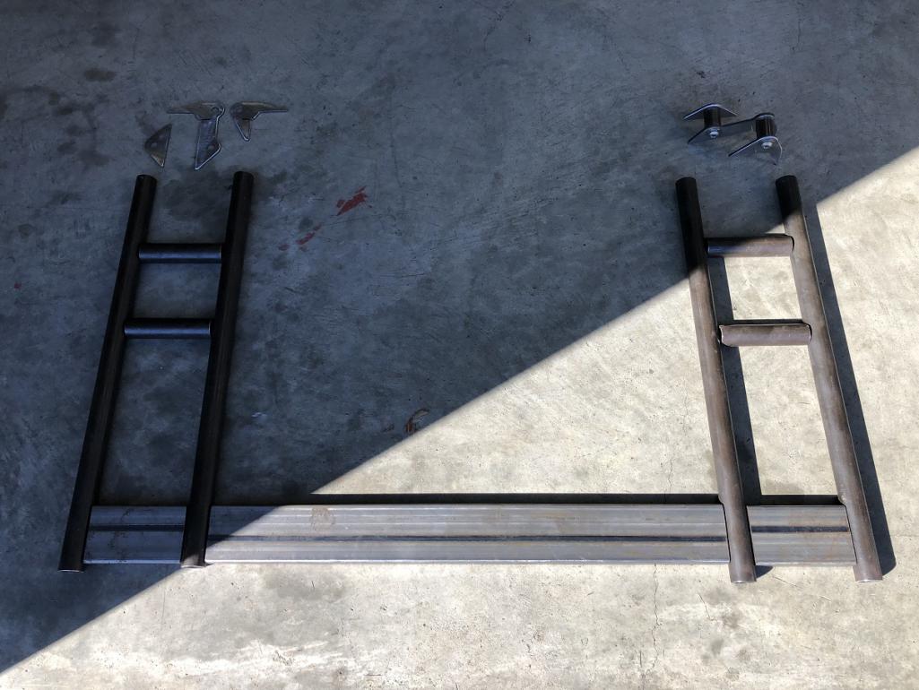
|
| tygaboy |
 Nov 12 2022, 06:09 PM Nov 12 2022, 06:09 PM
Post
#393
|
|
914 Guru      Group: Members Posts: 5,452 Joined: 6-October 15 From: Petaluma, CA Member No.: 19,241 Region Association: Northern California 
|
Today Martin and I went to another buddy's shop to borrow his lathe and mill.
First was the lathe, to face both ends of the bungs, then measure and trim them to final length. Attached thumbnail(s) 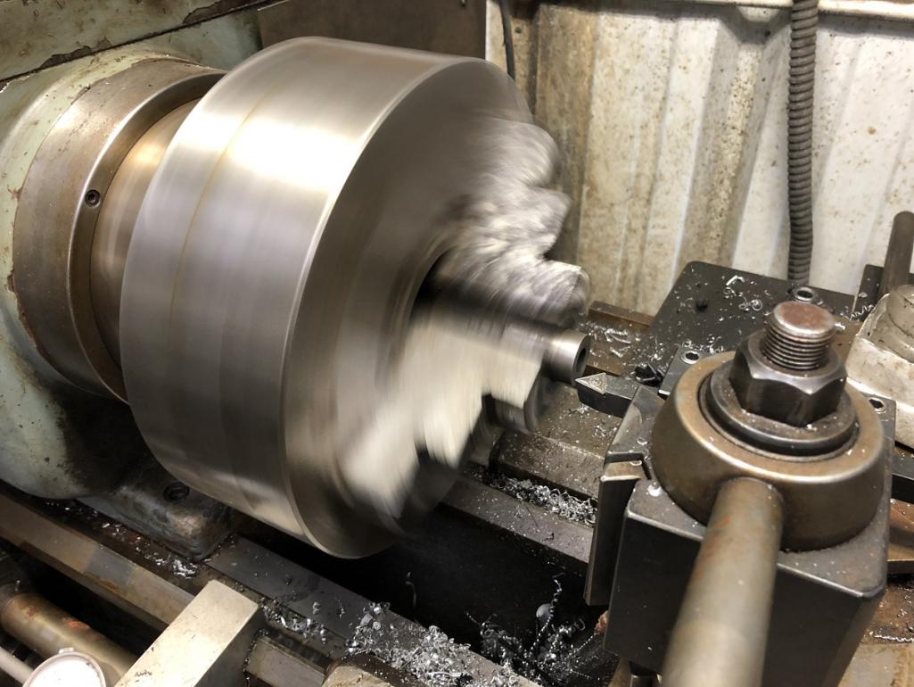
|
| tygaboy |
 Nov 12 2022, 06:10 PM Nov 12 2022, 06:10 PM
Post
#394
|
|
914 Guru      Group: Members Posts: 5,452 Joined: 6-October 15 From: Petaluma, CA Member No.: 19,241 Region Association: Northern California 
|
Next, it was into the mill with the cradle tubes to cut the... wait for it... bung hole! (IMG:style_emoticons/default/bootyshake.gif) (IMG:style_emoticons/default/shades.gif)
Attached thumbnail(s) 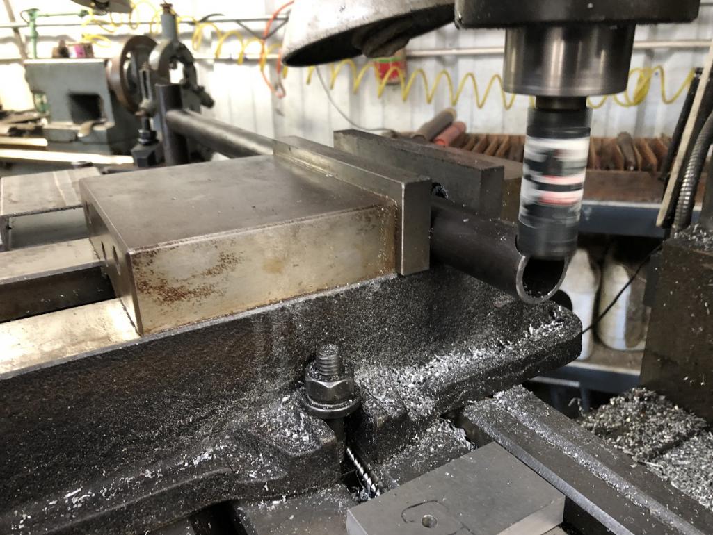
|
| tygaboy |
 Nov 12 2022, 06:13 PM Nov 12 2022, 06:13 PM
Post
#395
|
|
914 Guru      Group: Members Posts: 5,452 Joined: 6-October 15 From: Petaluma, CA Member No.: 19,241 Region Association: Northern California 
|
Nothing like having the proper tools available. Super nice result!
The outer edges of that excess material will be trimmed back and the remaining will be wrapped around the bung ahead of welding. Attached thumbnail(s) 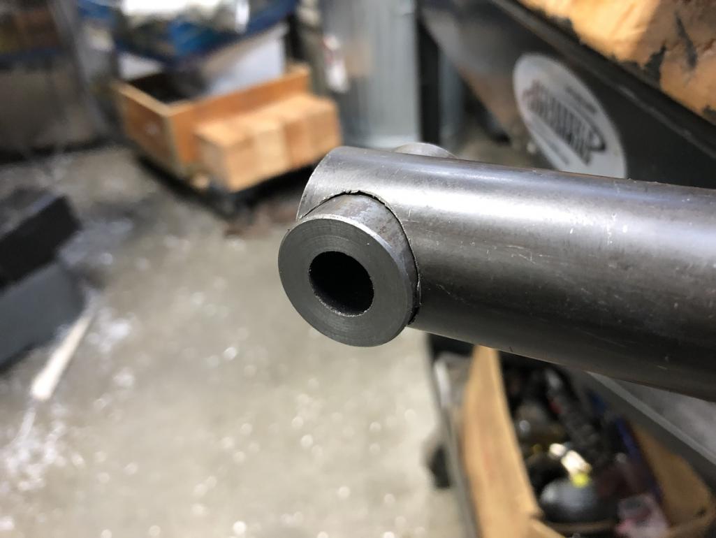
|
| Cairo94507 |
 Nov 28 2022, 08:40 AM Nov 28 2022, 08:40 AM
Post
#396
|
|
Michael           Group: Members Posts: 10,093 Joined: 1-November 08 From: Auburn, CA Member No.: 9,712 Region Association: Northern California 
|
Looking forward to some new pictures on this after 2 weeks of no World. (IMG:style_emoticons/default/beerchug.gif)
|
| tygaboy |
 Nov 28 2022, 09:21 AM Nov 28 2022, 09:21 AM
Post
#397
|
|
914 Guru      Group: Members Posts: 5,452 Joined: 6-October 15 From: Petaluma, CA Member No.: 19,241 Region Association: Northern California 
|
You'd think I'd have made a ton of progress in the past couple weeks. Well, if you count design changes, I did!
Remember, this cradle will be attached to the drivetrain and the entire set up then offered up to the chassis. So, after seeing the "vertical tabs" model mocked into the chassis, I realized the odds of being able to get all of the mounting bungs to slip into those slots, at the same time, at the necessary angle, on my contraption jack set up would be, um, "low". Why don't I think these things through on paper before I make parts? (IMG:style_emoticons/default/headbang.gif) Look at the how things mount in the 914. In the 911. All the mounts are horizontally oriented. I am such a doofus sometimes. OK, many times... The good news is all I had to do was rotate the cradle tubes 90 degrees, update the fire wall tab system to account for a horizontal orientation and cut the new parts. With that done I could fixture up the cradle tubes and get things tacked. Here are a few pics of the fixture set up being used to build each cradle side, then to position the cross bar. Again, having this table is like cheating. Attached thumbnail(s) 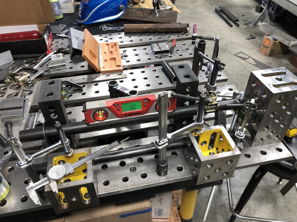 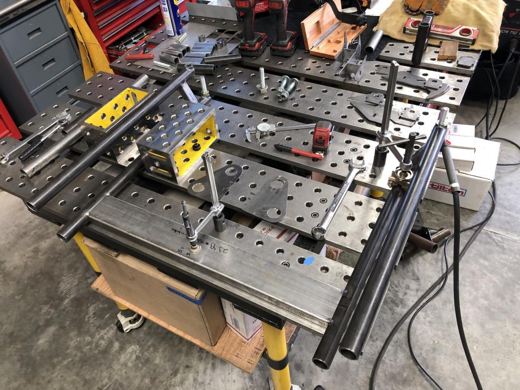 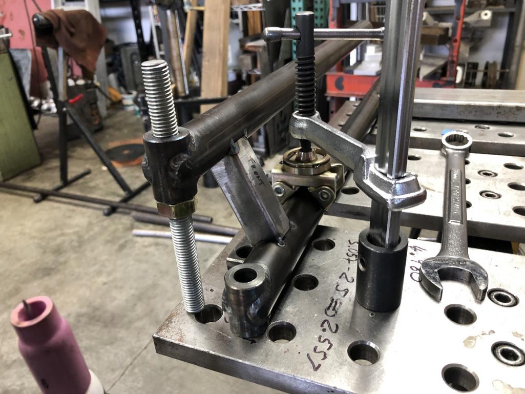 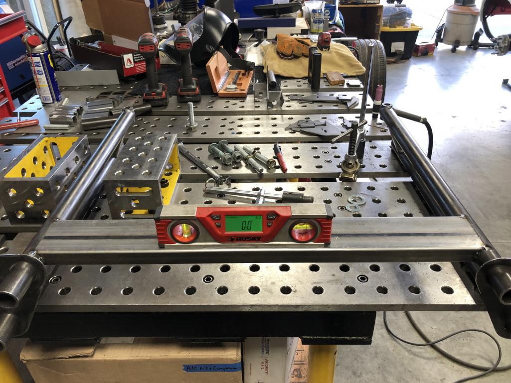
|
| tygaboy |
 Nov 28 2022, 09:29 AM Nov 28 2022, 09:29 AM
Post
#398
|
|
914 Guru      Group: Members Posts: 5,452 Joined: 6-October 15 From: Petaluma, CA Member No.: 19,241 Region Association: Northern California 
|
And here's the horizontal tab set. One thing I did account for is that the fire wall isn't necessarily 90 degress to the chassis. To account for that, I used a tab/slot approach with the tabs and mounting plates so that once the tabs are tight against the fire wall and the cradle is mocked into position, the mounting plates have enough slop that they can rotate to their "happy place" within the tabs and self-locate to the exact position needed.
See? Sometimes I'm all over a good approach! (IMG:style_emoticons/default/laugh.gif) Note, too, that I went after the edges of the mounting tabs with my little metal router. It makes for a really nicely finished part. Attached thumbnail(s) 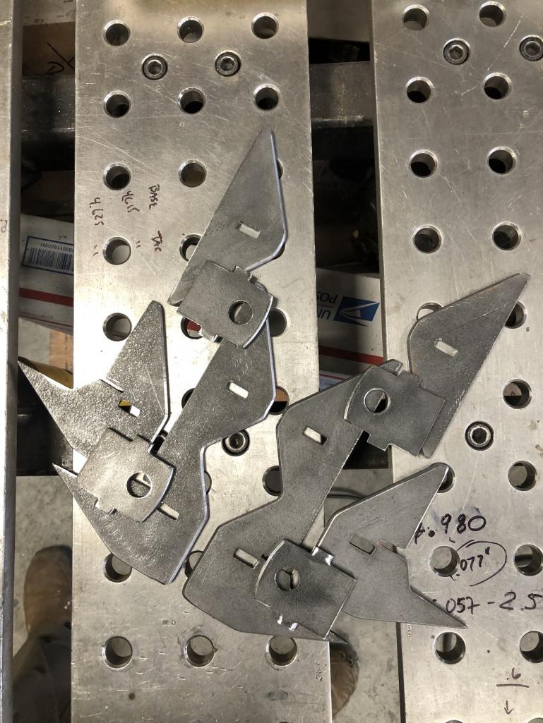 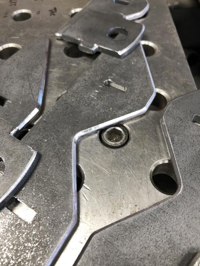
|
| tygaboy |
 Nov 28 2022, 09:33 AM Nov 28 2022, 09:33 AM
Post
#399
|
|
914 Guru      Group: Members Posts: 5,452 Joined: 6-October 15 From: Petaluma, CA Member No.: 19,241 Region Association: Northern California 
|
Cradle mocked in place, successfully demonstrating that all the measuring was accurate. I have the needed clearance at the alternator and the cross bar sits just where I wanted it, with plenty of clearance to the drivetrain.
Attached thumbnail(s) 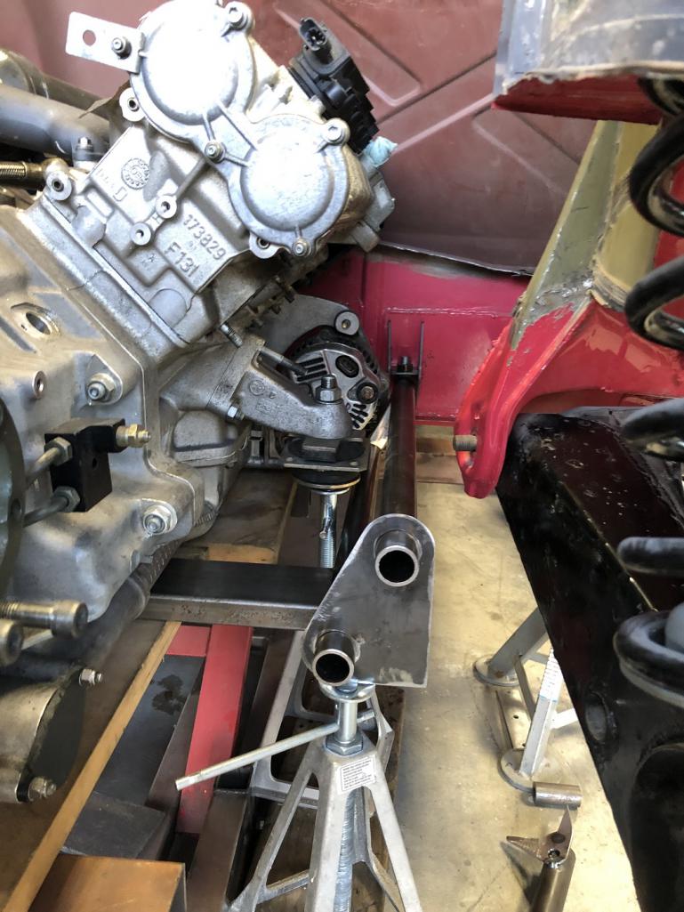 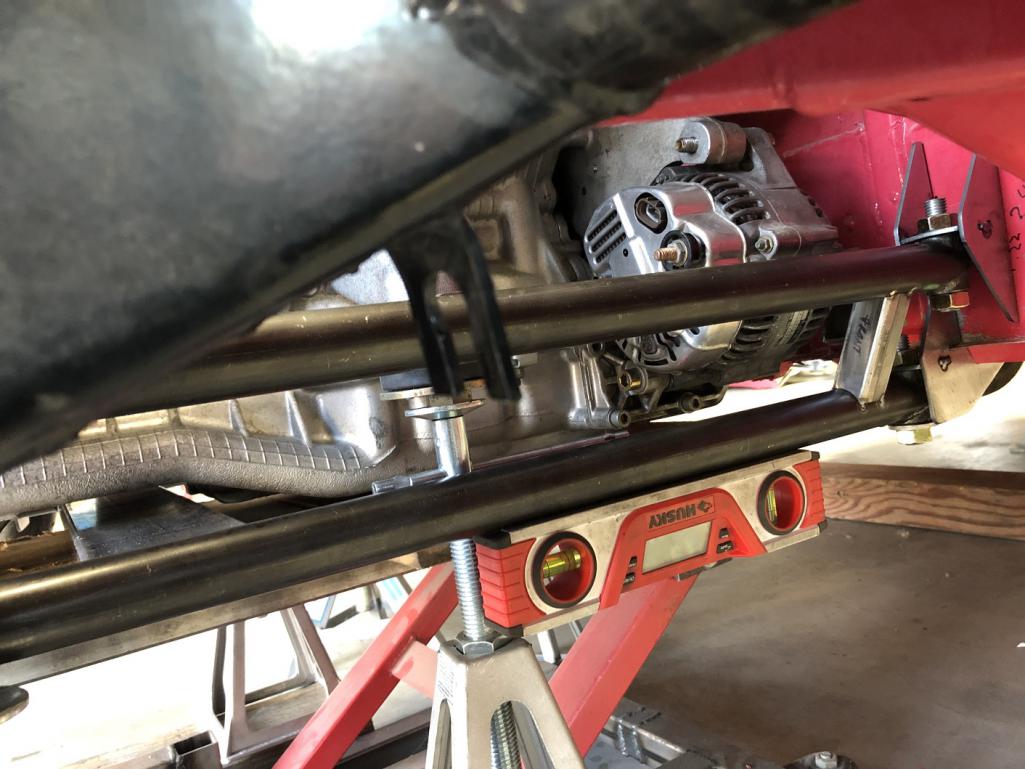
|
| tygaboy |
 Nov 28 2022, 09:42 AM Nov 28 2022, 09:42 AM
Post
#400
|
|
914 Guru      Group: Members Posts: 5,452 Joined: 6-October 15 From: Petaluma, CA Member No.: 19,241 Region Association: Northern California 
|
Next, it was on to the engine mount brackets. Here's the current design.
What's neat is that you can cut the holes with a bit over 180 degrees remaining and "snap" the piece over the tube. It really helps simplify mocking it into position as it pretty much holds itself in place. There will be one of these plates on each side of the mount with a vertical plate between them. Note that I routered the opening but didn't yet get to the outside edges. Attached thumbnail(s) 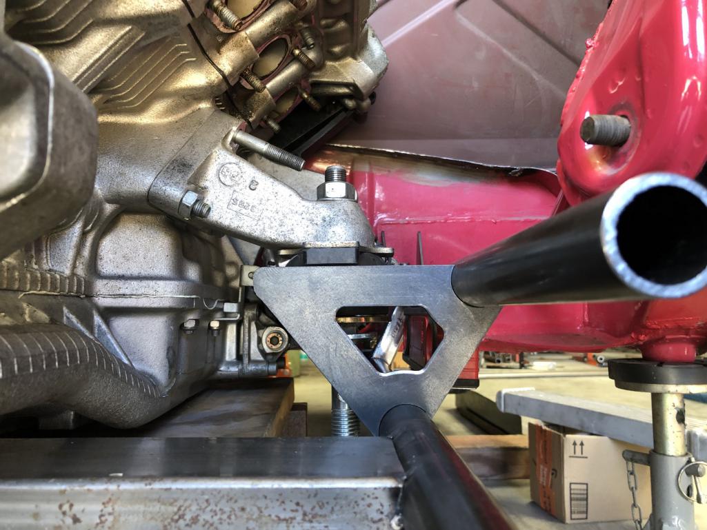 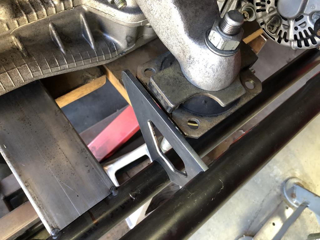
|
  |
1 User(s) are reading this topic (1 Guests and 0 Anonymous Users)
0 Members:

|
Lo-Fi Version | Time is now: 23rd November 2024 - 05:43 PM |
Invision Power Board
v9.1.4 © 2024 IPS, Inc.


