|
|
|
Porsche, and the Porsche crest are registered trademarks of Dr. Ing. h.c. F. Porsche AG.
This site is not affiliated with Porsche in any way. Its only purpose is to provide an online forum for car enthusiasts. All other trademarks are property of their respective owners. |
|
|

  |

| McMark |
 Jan 26 2007, 03:08 PM Jan 26 2007, 03:08 PM
Post
#1
|
|
914 Freak!  Group: Retired Admin Posts: 20,179 Joined: 13-March 03 From: Grand Rapids, MI Member No.: 419 Region Association: None |
I've been thinking about this for a long time. I would like to be able to quantitatively evaluate chassis stiffness. I have some ideas for increasing stiffness, but I'd like to be able to measure those changes by something other than the seat of my pants ("It feels stiffer.").
My best idea so far is to place a car on three jack stands of equal height and measure the droop of the fourth corner. Any other ideas? Any physicists that can help out here? |
   |

 
|
| messix |
Jan 26 2007, 03:35 PM
Post
#2
|
|
AKA "CLUTCH KILLER"! Group: Members Posts: 6,995 Joined: 14-April 05 From: between shit kickers and pinky lifters/ puget sound wa.north of Seattle south of Canada Member No.: 3,931 Region Association: Pacific Northwest |
it would seem that you would need to measure chassis rigidity with the suspension installed and locked to not allow the shocks to move. then you could manipulate the points of the suspension to find the torsional flex of the chassis.
|
|
|
|
| TravisNeff |
Jan 26 2007, 03:39 PM
Post
#3
|
|
914 Guru Group: Members Posts: 5,082 Joined: 20-March 03 From: Mesa, AZ Member No.: 447 Region Association: Southwest Region |
The only thing I could think of is to attach the chassis to a frame jig (like a cellete bench) and leave 1 corner free - then move the suspension and measure deflection one corner at a time.
|
|
|
|
| r_towle |
Jan 26 2007, 04:46 PM
Post
#4
|
|
Custom Member Group: Members Posts: 24,624 Joined: 9-January 03 From: Taxachusetts Member No.: 124 Region Association: North East States |
I would say build four custom jack stands that bolt to the suspension points on the chassis.
Three could be used, depending upon which corner you are testing. they would need to be rigid, with no suspension. Rich |
|
|
|
| JPB |
Jan 26 2007, 05:13 PM
Post
#5
|
|
The Crimson Rocket smiles in your general direction. Group: Members Posts: 2,927 Joined: 12-November 05 From: Tapmahamock, Va. Member No.: 5,107 |
I think torsion would be a snap. Just need to ballance the center of the car on a level I-beam. Fix solidly the opposit end of the car you will test. Lets say you want to test the rear, you then fix the front with a little frame bolted to the floor underneath the car. You then use a hydrolic item like Portapower to push and pull on opposit rear corners of the car and use the guages for a reading. You can do the same in the front. You can also test for sag by pulling on all four corners if thats what you want. You can also precamber your chassy and weld it up to stiffen even more. Hey, this sounds like gonna have a party fun (IMG:style_emoticons/default/beer.gif)
|
|
|
|
| Ferg |
Jan 26 2007, 05:38 PM
Post
#6
|
|
914 Guru Group: Members Posts: 5,948 Joined: 8-January 03 From: Boulder CO Member No.: 116 Region Association: None |
I agree with Rich. 3 Custom jack stands that bolt to suspension points, and then bolt to the floor. Use a laser pointer leveled on each corner of the car to measure movement on a fixed wall. (IMG:style_emoticons/default/confused24.gif)
Ferg |
|
|
|
| TonyAKAVW |
Jan 26 2007, 06:05 PM
Post
#7
|
|
That's my ride. Group: Members Posts: 2,151 Joined: 17-January 03 From: Redondo Beach, CA Member No.: 166 Region Association: None |
I'm assuming torsional stifness is what you want to measure. in that case, fix 3 points, vary the 4th. The fixing of the other three points would require that those jackstands be bolted to the floor I imagine.
Then to find out the stiffness, you put a jack on a scale and measure the force needed to lift the body some predetermined amount. That would be your torsional stiffness in pounds (of force) per inch (of travel). -Tony |
|
|
|
| IronHillRestorations |
Jan 26 2007, 06:26 PM
Post
#8
|
|
I. I. R. C. Group: Members Posts: 6,761 Joined: 18-March 03 From: West TN Member No.: 439 Region Association: None |
I saw one of the '97 GT1 tubs on a chassis dyno at Weissach. It was a special fixture made into the floor of the race shop and had what I'd guess to be 6" I beams about 15' long, spaced about 1" apart. There was probably 12 or 14 of them. They had the tub fastened to this and about 30 dial indicators and holders all over the tub. They used hydraulics to put force at different places on the tub and then recorded the changes.
When I say chassis dyno, it wasn't to measure horsepower, but the flex of the chassis. I would bet they probably used this fixture to build space frames too. Very cool stuff, once in a lifetime trip. I would say you have to secure the entire chassis, and release a corner or section at a time in order to correctly measure the flex. About six weeks ago I purchased an old Blackhawk frame bench. I plan to replicate the Celette type of fixtures specifically for a 914. |
|
|
|
| Mid_Engine_914 |
Jan 26 2007, 08:19 PM
Post
#9
|
|
Member Group: Members Posts: 195 Joined: 22-September 06 From: Left Coast Member No.: 6,888 |
Contact a few engineering consulting firms and ask them. Car manufacturers measure chassis stiffness by the frequency that the chassis naturally vibrates at. I have no idea how it's done or if it's easy to do.
I think I saw these guys do suspension engineering and chassis stiffening on old Mopars on Dream Car Garage http://www.multimatic.com/engineering/index.shtml This post has been edited by Mid_Engine_914: Jan 26 2007, 08:37 PM |
|
|
|
| TonyAKAVW |
Jan 26 2007, 08:47 PM
Post
#10
|
|
That's my ride. Group: Members Posts: 2,151 Joined: 17-January 03 From: Redondo Beach, CA Member No.: 166 Region Association: None |
To measure a chassis' resonsant frequency you have to mount the whole chassis to a giant transducer (speaker voice coil) and either pump it with white noise or sweep it from very low to very high frequency. I imagine this would have to be done in an acoutsically neutral (anechoic chamber) room to get good results.
For turbine blades and other stuff, they illuminate the whole thing with a pair of lasers and you can see the modes visibly as interference patterns. I think you have to polarize the light at some point... Anyway, not cheap, not easy is my guess. -Tony |
|
|
|
| r_towle |
Jan 26 2007, 09:17 PM
Post
#11
|
|
Custom Member Group: Members Posts: 24,624 Joined: 9-January 03 From: Taxachusetts Member No.: 124 Region Association: North East States |
The whole chassis resonance thing was done, and a detailed article of the test on a 914 appeared in "up-fixin der porsche" (I forget which one)
The test was done in a big lab in CA, and the results were a cage built to add strength the the 914. McMark, If you want to personally test and existing car, or a customers car as you are working on it...build a jig. I would think that two fixtures (jack stands) bolted to the suspension ear, and two bolted to the opening in the fender where the strut bolts (without the bearing) would be enough to measure not only a twisted condition, but the current state of flex... Rich |
|
|
|
| rick 918-S |
Jan 26 2007, 09:43 PM
Post
#12
|
|
Hey nice rack! -Celette Group: Members Posts: 20,680 Joined: 30-December 02 From: Now in Superior WI Member No.: 43 Region Association: Northstar Region |
QUOTE(r_towle @ Jan 26 2007, 07:17 PM)  The whole chassis resonance thing was done, and a detailed article of the test on a 914 appeared in "up-fixin der porsche" (I forget which one) The test was done in a big lab in CA, and the results were a cage built to add strength the the 914. McMark, If you want to personally test and existing car, or a customers car as you are working on it...build a jig. I would think that two fixtures (jack stands) bolted to the suspension ear, and two bolted to the opening in the fender where the strut bolts (without the bearing) would be enough to measure not only a twisted condition, but the current state of flex... Rich Build one like this. Attached image(s) 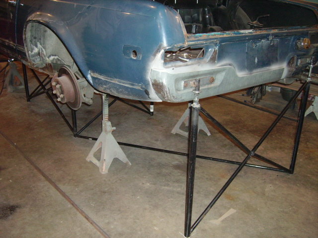
|
|
|
|
| rick 918-S |
Jan 26 2007, 09:57 PM
Post
#13
|
|
Hey nice rack! -Celette Group: Members Posts: 20,680 Joined: 30-December 02 From: Now in Superior WI Member No.: 43 Region Association: Northstar Region |
here's a couple more
Attached image(s) 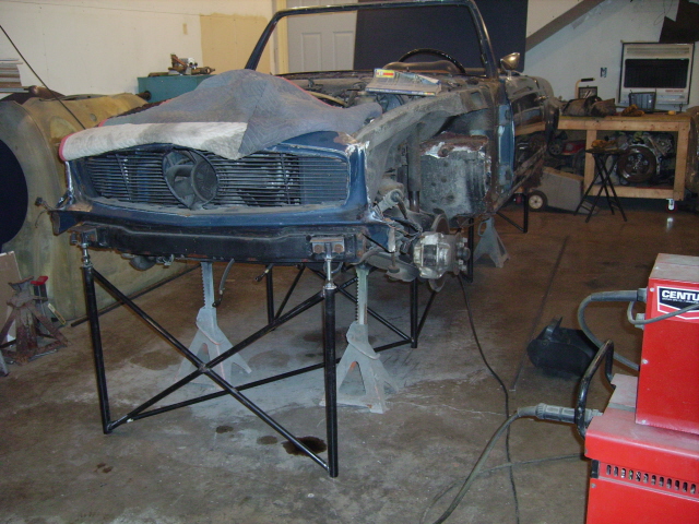
|
|
|
|
| alpha434 |
Jan 26 2007, 10:01 PM
Post
#14
|
|
My member number is no coincidence. Group: Members Posts: 3,154 Joined: 16-December 05 From: Denver, CO Member No.: 5,280 Region Association: Rocky Mountains |
Doesn't any of the local shops around you have a shaker table?
I actually have the shaker table data for my '75 around here someplace.... We threw a couple 356s and a short wheelbase 911 on there, too. |
|
|
|
| rick 918-S |
Jan 26 2007, 10:02 PM
Post
#15
|
|
Hey nice rack! -Celette Group: Members Posts: 20,680 Joined: 30-December 02 From: Now in Superior WI Member No.: 43 Region Association: Northstar Region |
All the tops are adjustable. I leveled the center check sets. You then can establish a datum line. and check the chassis for sag. This particular car was poorly repairs. I'm correcting the last guys mistakes. With the front and rear adjustment I'm able to correct the door gaps and top fit.
Attached image(s) 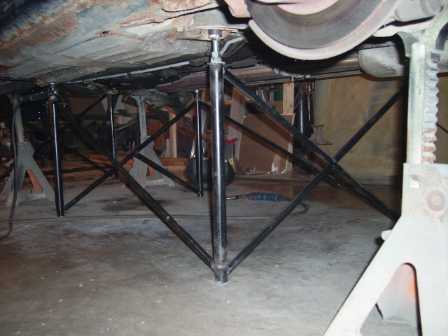
|
|
|
|
| rick 918-S |
Jan 26 2007, 10:05 PM
Post
#16
|
|
Hey nice rack! -Celette Group: Members Posts: 20,680 Joined: 30-December 02 From: Now in Superior WI Member No.: 43 Region Association: Northstar Region |
Mark once you get the chassis leveled in a jig like this you could crank one of the threaded points down and measure any drop in the chassis.
|
|
|
|
| McMark |
Jan 26 2007, 11:45 PM
Post
#17
|
|
914 Freak! Group: Retired Admin Posts: 20,179 Joined: 13-March 03 From: Grand Rapids, MI Member No.: 419 Region Association: None |
QUOTE(Ferg @ Jan 26 2007, 03:38 PM) I don't have any fixed walls, mine all move... (IMG:style_emoticons/default/blink.gif) (IMG:style_emoticons/default/av-943.gif) |
|
|
|
| McMark |
Jan 26 2007, 11:49 PM
Post
#18
|
|
914 Freak! Group: Retired Admin Posts: 20,179 Joined: 13-March 03 From: Grand Rapids, MI Member No.: 419 Region Association: None |
Cool stuff, Rick.
It sounds like I'm on the right track. Fix three points, vary the fourth. I was thinking something along the lines of using a spring scale to see how much force is needed to move the variable corner 0.5" or some such. |
|
|
|
| rick 918-S |
Jan 26 2007, 11:51 PM
Post
#19
|
|
Hey nice rack! -Celette Group: Members Posts: 20,680 Joined: 30-December 02 From: Now in Superior WI Member No.: 43 Region Association: Northstar Region |
I'm not sure it would be a good idea to viberate a 30 year old chassis... (IMG:style_emoticons/default/blink.gif) I guess this would help remove some of the rust but that's about it at this point. (IMG:style_emoticons/default/av-943.gif)
effin wireless.. I just had a long response drop when I tried to post. |
|
|
|
| Mugs914 |
Jan 27 2007, 04:13 AM
Post
#20
|
|
"Hey, yellow IS faster!" Group: Members Posts: 618 Joined: 22-July 05 From: Temple TEXAS Member No.: 4,452 Region Association: Southwest Region |
Typical practice among race engineers is to express chassis stiffness in foot-pounds per degree of twist. Of course an F-1 tub won't twist anywhere near 1 whole degree, and they have all kind of test rigs to give them NASA accurate numbers, but the results are still expressed the same way.
It would be pretty easy to test a 914 tub. Your rig would need to secure one end, let's say the rear, to the floor by the top shock mounts since this is where the vertical loads are fed into the tub (Chassis twisting loads are the result of vertical loads being fed into the tub by the tire via the suspension, so the test needs to measure the stiffness between the points where the spring loads are fed into the tub). The other end of the tub can be supported in the centre by a single point (jackstand (IMG:style_emoticons/default/smile.gif) ) and a l-o-n-g arm attached by the crossmember mounting bolts (vertical loads in the front go through the torsion bar end caps. If you have coil-overs up front, use the shock towers.). Measure ten feet from the centre point out toward the end of the arm and add weight until you measure 1 degree of twist at the front centreline. Multiply the weight required by ten (feet) and you have a result in foot-pounds per degree. This works, and even if the actual numbers aren't 100 percent accurate you're still able to tell whether your mods are effective as long as you are consistent with your test methods. For example, if you have 300 pounds out on the arm (times ten feet) and only see .5 of a degree, it might not (probably won't) mean you have an honest-to-God 6000 pound-foot per degree stiffness, but if it takes 400 pounds to get the same .5 of a degree after your mods you done good! Of course, like Rick said, twisting the business out of a thirty year old tub might scare ya... I've been thinking about building a rig like this to test the race car. Maybe I should do it sooner rather than later... |
|
|
|
|
1 User(s) are reading this topic (1 Guests and 0 Anonymous Users)
0 Members:

|
Lo-Fi Version | Time is now: 27th September 2024 - 11:50 AM |
Invision Power Board
v9.1.4 © 2024 IPS, Inc.