Help - Search - Members - Calendar
Full Version: MPS Tuning Analysis
914World.com > The 914 Forums > 914World Garage
Pages: 1, 2
Not_A_Six
EDIT: See post #17 for an update that contradicts some of the findings in this OP. See also post #29 for the final results.

I've recently gone down the rabbit hole of D-Jet and MPS tuning and wanted to post what I've learned in the hopes that it may help others. I also hope to start a discussion with some of the experts here in case I've missed something, or there are errors in my analysis.

Background:

With the increased displacement (2056cc) and non-stock cam (Webcam 73) in my engine, I was experiencing Air-Fuel Mixture (AFR) issues across the range of temperature, load, and rpm conditions.

This post concerns MPS tuning. At the moment, I'm also working on modifying component values inside the ECU to change the Volumetric Efficiency curve to better match the non-stock AFR vs RPM characteristics of my engine. If there is any interest in poking around that deep in the bowels of D-Jet, I'll start a thread when I finish. blink.gif

Engine Configuration:

'73 2.0
Displacement: 2056cc
Cam: Webcam 73
ECU: Porsche nnn906021E (Bosch 280000037)
MPS: Porsche 022906051E (Bosch 0280100049) w/ Tangerine Racing tuning kit + spacer ring; tuned to emulate 0280100037
CHT: 0280130017 w/ 270-ohm ballast resistor and steel spacer
Vacuum Hoses routed per @JeffBowlsby (see link below)
Fuel Pressure: 35 psi (at the moment -- still tuning)
PCV: Modern PCV valve routed to plenum
Ignition: 123Ignition PORSCHE-4-R-V-IE, running profile "1" w/ Vac Advance
Timing: 27 degrees at 3500 rpm (w/o vacuum adv/ret)

Equipment used:
Generic handheld vacuum pump/gauge
misc hoses+fittings
AMPROBE LCR55A meter (on 20H scale)
Innovate Motorsports (3837) LM-2 (BASIC) Digital Air/Fuel Ratio Wideband Meter w/ Bosch LSU 4.9
Home-fabricated tailpipe "Stinger" w/ O2 Sensor Bung TIG welded on

Reference Info:
Vacuum Hose Routing
MPS Theory of Operation @pbanders
AFR vs Manifold Vacuum Issue @Demick


Analysis:

Click to view attachment

As you can see in the "Chart A" sketch above, the MPS Inner Screw (in isolation), Outer Screw+Inner Screw (together), and Stop Plug Screw can be used to tune the MPS's affect on the AFR (via its effect on the Fuel Injection pulse width) vs Manifold Vacuum. As shown, the Inner Screw affects the mixture over the whole vacuum range; the Inner+Outer Screw controls the onset pressure P' where the diaphragm begins to lift off the part-load stop; the Stop Plug Screw controls the final pressure P'' where the diaphragm comes to rest on the full-load stop. On this chart, "up" corresponds to a longer FI pulse; "down" to a shorter FI pulse. For details, see pbanders's excellent link, above.

I had previously thought that the effect of the Inner Screw was similar to that of changing the fuel pressure via the fuel pressure regulator. Namely:

Inner Screw CCW = Increase Fuel Pressure => Richer AFR across entire vacuum range
Inner Screw CW = Decrease Fuel Pressure => Leaner AFR across entire vacuum range

There appeared to be no way to change the slope of the MPS Response curve in the region from 15 In-Hg to P'. And, I was experiencing the same problem that Demick posted about years ago in the thread linked above. Namely, the AFR would become too lean under moderate-load conditions across all RPM's, like this (from Demick's post):

IPB Image

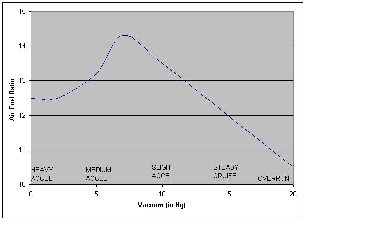
To fix the lean condition around 6-8 In-Hg, it's really necessary to change the slope of the MPS response curve, not just raise or lower the whole curve.

However, there appears to be hope. It seems that the MPS inductance is not simply linear WRT manifold pressure in the 15 In-Hg to P' region. I speculate that this may be due to non-linearity in the MPS Inductance across its range of movement and/or the effect of the MPS spring. The result is that the curve seems to look more like the "Chart B" sketch above. And, the effect of turning the MPS inner screw isn't really raising or lower the entire curve, but rather shifting the Chart B curve left/right. (Chart B is a really rough sketch, and may even have the convexity backwards. For a more quantitative look, see below.)

I measured the inductance of my MPS at two different inner-screw settings: The red curve is the MPS tuned to pbanders's values corrected for 700 Torr ambient pressure. The blue curve represents an attempt to richen the AFR by turning the inner screw CCW.

Click to view attachment

As you can see, the slope of the red curve is steeper than the blue curve in this region. Apparently, turning the inner screw CCW has the effect of reducing the slope by raising the right end, rather than raising the whole curve.

I'm surprised that the curves cross around 7 In-Hg and that the blue curve value is less than the red curve value at the left side of the chart. This may be due to the effect of the part-load stop coming into play near P', measurement error, or something else. confused24.gif

The salient point, however, is that adjusting the inner screw affects the slope of the curve, whereas presumably adjusting the fuel pressure does not.

The opens the possibility of tuning the AFR vs Manifold pressure curve by trading off fuel pressure vs inner screw position:

Increase Fuel Pressure + Turn Inner Screw CW => Enrich 6-8 In-Hg region
Decrease Fuel Pressure + Turn Inner Screw CCW = Lean out 6-8 In-Hg region

I experienced the same problem that Demick did (too lean at 6-8 In-Hg across all RPM), and have largely solved the problem by adjusting the fuel pressure up (to 35 psi currently), then tuning the MPS to set the AFR across the entire range of manifold vacuum levels.

I hope this is helpful to somebody. Comments are welcome. If I've made any errors, please feel free to beat me over the head. splat.gif

Cheers. beerchug.gif
Olympic 914
I will be watching this closely.

Had considered opening a thread similar with my results/findings

My AFR gauge just took a dump and was returned to Auto Meter for repair.

Similar engine config.

Will try my best to follow your explanations.
JOEPROPER
This is a great thread with great links. A lot of really good information. Thanks for posting.
I will probably be adjusting my MPS for my 2056, but wonder how often this is necessary in a stock application. The epoxy leads me to believe that these were adjusted in the factory and were to be left alone after. After 45+ years, I guess some adjustment may be necessary, but were probably not expected to last that long.
Bleyseng
With a stock cam and the slight increase in piston size you shouldn't need to adjust the MPS. "Shouldn't" is the key word as always after 45 years your setup should be tested for correct air fuel ratios with a wide band or on a rolling dyno. driving.gif
Not_A_Six
QUOTE(Bleyseng @ Aug 15 2020, 01:21 PM) *

With a stock cam and the slight increase in piston size you shouldn't need to adjust the MPS. "Shouldn't" is the key word as always after 45 years your setup should be tested for correct air fuel ratios with a wide band or on a rolling dyno. driving.gif


I agree. The bigger displacement should have a larger appetite for fuel than stock. But with a stock cam, you can likely compensate just by bumping up the fuel pressure a bit, and get it to run "good enough" -- if everything else is working properly. smile.gif

If you want to go down to the next level in the dungeon, you may want to tune the MPS with a Tangerine kit and wideband O2 meter.

If you want to descend all the way to the lowest level of D-Jet hell, you may have to tune the ECU component values to adjust the VE curve at specific RPM's. (Likely unneeded with the stock cam.) happy11.gif
JOEPROPER
Webcam 73...
Not_A_Six
QUOTE(JOEPROPER @ Aug 15 2020, 04:56 PM) *

Webcam 73...


Your engine setup sounds similar to mine then. I couldn't get mine to run to my satisfaction across temp/load/rpm. And, so began my descent into madness... prop.gif

But, I'm an obsessive engineering geek. I'd start with the fuel pressure and see if you're happy with the results. A little richness can cover up a lot of niggling issues. Good luck. Please post your results.

Cheers. beerchug.gif
Olympic 914
On your Blue/Red graph, how many data points did you use? Every( in Hg) ?

I was thinking of mapping my MPS. Was there a reason you did not map it to "0"

Did you correct your numbers to sea level? Could you share the formula? please keep it simple for me.

My location is about 1000 ft alt

BeatNavy
Just for fun I'll throw in some of my data and "analysis" from a few years ago. This was when I was trying to tune a 2056 with a stock cam and later a 2056 with a Raby 9950 (or 9550, whichever it is). I think the latter is similar to a Webcam 73, or maybe even the same grind.

I ended up comparing the following for vacuum / inductance numbers for the 043 MPS, which should have been correct for my '74 D-Jet setup (and compatible with the 043 ECU):

1. Anders' numbers for MPS tuning on his website.
2. An 043 "Primary" that I rebuilt using Chris Foley's kit. This was the one I fiddled with the most in terms of tuning and driving.
3. 043 "Spare." This one was also rebuilt, and I used this kind of as my fallback if I screwed up the primary too badly. I also used it to compare how the car ran with the other one.
4. 043 "Reman." This one was rebuilt and tuned years ago by that company that used to perform this service years ago ("Fuel Injection Company" or whatever it is/was). I did not mess with this one.
5. 043 "Stock." Thanks to the yard sale at Jim McLeod's (RIP sad.gif ) a couple of years ago I managed to acquire a working, unmolested 043. Used this primarily to baseline my inductance meter's numbers against those of Anders.

Here are the results in table form. Remember, I was primarily tuning 043 "Primary" and "Spare," so those numbers could be all over the place. I've got the slope in there, but the most relevant slope is that over the "linear region" which I think Anders defines as between 6 and 18 in Hg.
Click to view attachment

And here's the graph, such as it is.
Click to view attachment

Here are my lessons learned:

1. I spend a LOT of time on this, and I learned a lot, which was enjoyable. But I got more return out of that than any performance increase or optimization smile.gif

2. Inductance meters seem to vary significantly. I'm not sure why this is (I know mine was a cheap one, not a Wavetek), but I know others have had similar findings. You can see that my stock 043 didn't even get close to Anders' numbers, which I found interesting. It also means you can't simply go by Anders' numbers if you are using those as a baseline.

3. Chasing AFR can be a challenge. Type 4 idle AFR can be very unreliable, and exhaust leaks and/or valve issues can really mess with the numbers. Different exhaust systems / bung location can also impact your values. I guess my point here is that trying to get to an exact AFR down to the tenth can be like chasing your tail. Sometimes it's more important to focus on what the car is telling you (how much that engine "likes" the tune in terms of performance, gas consumption, plug fouling, etc. etc.).

4. I took a tip from a member here (Frank, I believe), and hooked up a "T" vacuum line from my MPS to a vac gauge in the cockpit. That was very helpful for understanding the relationship between "part load," throttle position, and AFR. It gave me a better understanding of when I should be looking for what AFR value. EDIT: in that regard, I should have changed the labels in the table above where 4 in Hg is not "cruise" but "strong acceleration" and 6 in Hg "acceleration."

5. D-Jet has limitations (of course). It works like a champ for what it was intended to do, but of course you can only tease so much out of it either in terms of fine-tuning or performance enhancements. Unless you REALLY get creative or go off the deep end. I've recently moved on to Microsquirt where I can now be ignorant in that arena smile.gif

Just my two cents for the OP who obviously has a much more rigorous scientific and analytical background than do I.

beerchug.gif
Bleyseng
Using a Wavetek just like Anders I came up with these numbers on a NOS 043 at sealevel :

15hg-.71
4hg-1.20
0hg-1.42

I found the best way is to tune your MPS to your car using a LM2 O2 setup. I
just hook it up and test drive the car at partload (cruise -4HG) and adjust the MPS to a AFR of 13.7 to 1. Then set the WOT to start at 11 to 1. Idle is adjusted by the ECU knob.

I think these engines are so old and parts are different than a brand new engine's spec's its impossible to expect to just plug in a NOS MPS and want it to be perfect.
Not_A_Six
QUOTE(Olympic 914 @ Aug 15 2020, 07:01 PM) *

On your Blue/Red graph, how many data points did you use? Every( in Hg) ?

I was thinking of mapping my MPS. Was there a reason you did not map it to "0"

Did you correct your numbers to sea level? Could you share the formula? please keep it simple for me.

My location is about 1000 ft alt


I measured the inductance and collected data from 0-15 In-Hg, at 1 In-Hg intervals. And, I have a bunch of different MPS "tunes" that I was experimenting with as I played with fuel pressure, ignition timing, etc.

On my graph, I just plotted the data from 5 to 15 In-Hg to show that the slope would change in that region as you turned the MPS inner screw. The red and blue curves diverge below 5 In-Hg due to different tuning in that region.

pbanders's values for the 028100037 MPS measured at 726 Torr (1260 ft elevation) are:

0 in Hg 1.44H
4 in Hg 1.26H
15 in Hg 0.72H

I'm at 2250 ft elevation (700 Torr). So, those values at my elevation are roughly:

0 in Hg 1.39H
4 in Hg 1.22H
15 in Hg 0.70H

The red curve on my graph was tuned to these values, and has data points every 1 In-Hg.

To adjust pbanders's numbers for my elevation, I used the simple straight-line method outlined in his MPS link in my OP. There are more accurate ways to make the altitude correction, but this was easy and good enough for my purposes:

"The simplest way to calculate a correction factor is to compare the absolute pressure of your location in Torr to my absolute pressure, 726 Torr. For example:

Sea level: absolute pressure is 760 Torr. Therefore, the correction factor is 760/723 = 1.05 . So, for a 0 280 100 043 MPS, the 0, 4, and 15 in. Hg calibration values would be, 1.45, 1.24, and 0.75 H, respectively."


All of these values were measured with an LCR55A meter on the 20H scale. That meter is now made by Amprobe instead of Wavetek. pbanders's values were apparently measured with an older Wavetek meter; mine were measured with a newer Amprobe version. I believe the calibration and values are the same for both meters.

It's important to note that the meter type/model and even scale used will likely read different values than those above. So, my numbers in this thread shouldn't be used as any sort of tuning values for any other MPS, in any other car, at any other elevation.

My tuning process was to start with pbanders's values adjusted for my altitude (the red curve), then make adjustments to fuel pressure and MPS from that starting point based on O2 readings while driving under different conditions.

FWIW, my goal AFR tuning values are:

Hot Idle: 12.5-13
Hot Cruise: 13-13.5
Hot WOT: 12.5

This is 45+ year-old d-jet, so those AFR numbers are expected to vary a bit over rpm, vacuum, engine temp, altitude, etc.

Cheers. beerchug.gif
Olympic 914
This is great.

I have been hoping others would post there numbers.

Like Rob I have three 043 MPS units with different tunes I adjust but its mostly looking at the AFR numbers and remembering when it whet lean or rich and making the changes.

also using a Amprobe LCR55A meter so I may be able to compare somewhat our numbers.

Will post later and add my 0 4 and 15 figures when I get a chance.

It does seem right now that my numbers are richer than Not a Six

also as stated above my AFR is out for service, though my Butt Dyno tells me its running better.

I really miss looking at the AFR gauge.
JeffBowlsby
"2. Inductance meters seem to vary significantly. I'm not sure why this is (I know mine was a cheap one, not a Wavetek), but I know others have had similar findings. You can see that my stock 043 didn't even get close to Anders' numbers, which I found interesting. It also means you can't simply go by Anders' numbers if you are using those as a baseline."

agree.gif

"I think these engines are so old and parts are different than a brand new engine's spec's its impossible to expect to just plug in a NOS MPS and want it to be perfect."

agree.gif FWIW I have had the opportunity to characterize multiple different NOS MPSs. Each has had somewhat different calibration, using the same Wavetek LCR55. Goes to show you there are no absolutes with this stuff. Let the specific engine tell you what it specifically needs using an O2 sensor or dyno. I have found that Brad's (Anders) numbers are lean when compared to calibration readings from my meter, as adjusted for elevation. My calibration numbers are richer than his.

"All of these values were measured with an LCR55A meter on the 20H scale. That meter is now made by Amprobe instead of Wavetek. pbanders's values were apparently measured with an older Wavetek meter; mine were measured with a newer Amprobe version. I believe the calibration and values are the same for both meters."

Who knows, there has never been a comparison and these are delicate numbers.

"I found the best way is to tune your MPS to your car using a LM2 O2 setup."

agree.gif
Superhawk996
biggrin.gif

Great thread. Love seeing a logical, methodical approach.
Not_A_Six
The main reason that different meters give different inductance readings is that *real* inductors (especially coupled ones like in an MPS) are not very linear devices -- their value is a function of voltage, frequency, etc.

Different meters use different frequencies, and even different waveform shapes (e.g. sine, triangle, square) to measure inductance. They also use different frequencies for different ranges. For example, the LCR55A uses a 1000 Hz frequency for the 200uH to 2H ranges, and 100 Hz for the 20H and 200H ranges.

I wouldn't get too hung up on the absolute inductance numbers if you are tuning an MPS on a particular car. The inductance values are just a starting point, as you'll likely be using AFR rather than inductance numbers to make adjustments. The 15 In-Hg value is pretty important as it relates directly to the part-load AFR. But, the 4 and 0 In-Hg numbers are just proxies for the P' and P'' pressures respectively.

IMO, It's the P' and P'' values that are much more valuable than the 0 or 4 In-Hg numbers.

If you measure a given MPS in 1 In-Hg increments with a given (pretty much any) meter, and plot the results, you can determine P' and P'' from the corners on the curve (which should look something like "Chart A" in my OP).


beerchug.gif
Not_A_Six
QUOTE(BeatNavy @ Aug 16 2020, 05:19 AM) *

Just for fun I'll throw in some of my data and "analysis" from a few years ago. This was when I was trying to tune a 2056 with a stock cam and later a 2056 with a Raby 9950 (or 9550, whichever it is). I think the latter is similar to a Webcam 73, or maybe even the same grind.

I ended up comparing the following for vacuum / inductance numbers for the 043 MPS, which should have been correct for my '74 D-Jet setup (and compatible with the 043 ECU):

1. Anders' numbers for MPS tuning on his website.
2. An 043 "Primary" that I rebuilt using Chris Foley's kit. This was the one I fiddled with the most in terms of tuning and driving.
3. 043 "Spare." This one was also rebuilt, and I used this kind of as my fallback if I screwed up the primary too badly. I also used it to compare how the car ran with the other one.
4. 043 "Reman." This one was rebuilt and tuned years ago by that company that used to perform this service years ago ("Fuel Injection Company" or whatever it is/was). I did not mess with this one.
5. 043 "Stock." Thanks to the yard sale at Jim McLeod's (RIP sad.gif ) a couple of years ago I managed to acquire a working, unmolested 043. Used this primarily to baseline my inductance meter's numbers against those of Anders.

Here are the results in table form. Remember, I was primarily tuning 043 "Primary" and "Spare," so those numbers could be all over the place. I've got the slope in there, but the most relevant slope is that over the "linear region" which I think Anders defines as between 6 and 18 in Hg.
Click to view attachment

And here's the graph, such as it is.
Click to view attachment

Here are my lessons learned:

1. I spend a LOT of time on this, and I learned a lot, which was enjoyable. But I got more return out of that than any performance increase or optimization smile.gif

2. Inductance meters seem to vary significantly. I'm not sure why this is (I know mine was a cheap one, not a Wavetek), but I know others have had similar findings. You can see that my stock 043 didn't even get close to Anders' numbers, which I found interesting. It also means you can't simply go by Anders' numbers if you are using those as a baseline.

3. Chasing AFR can be a challenge. Type 4 idle AFR can be very unreliable, and exhaust leaks and/or valve issues can really mess with the numbers. Different exhaust systems / bung location can also impact your values. I guess my point here is that trying to get to an exact AFR down to the tenth can be like chasing your tail. Sometimes it's more important to focus on what the car is telling you (how much that engine "likes" the tune in terms of performance, gas consumption, plug fouling, etc. etc.).

4. I took a tip from a member here (Frank, I believe), and hooked up a "T" vacuum line from my MPS to a vac gauge in the cockpit. That was very helpful for understanding the relationship between "part load," throttle position, and AFR. It gave me a better understanding of when I should be looking for what AFR value. EDIT: in that regard, I should have changed the labels in the table above where 4 in Hg is not "cruise" but "strong acceleration" and 6 in Hg "acceleration."

5. D-Jet has limitations (of course). It works like a champ for what it was intended to do, but of course you can only tease so much out of it either in terms of fine-tuning or performance enhancements. Unless you REALLY get creative or go off the deep end. I've recently moved on to Microsquirt where I can now be ignorant in that arena smile.gif

Just my two cents for the OP who obviously has a much more rigorous scientific and analytical background than do I.

beerchug.gif


BeatNavy, That's awesome data! Thanks.

Your "Anders" values look like they are for 1280 ft el (726 Torr). At what elevation did you measure the others? (I assume your values are raw -- uncorrected for elevation.)

"I spend a LOT of time on this, and I learned a lot, which was enjoyable. But I got more return out of that than any performance increase or optimization"

Yeah! No kidding. I've got way too much time in this so far, but I think it's been really worthwhile. The most valuable stuff for me was 1) Getting a wideband O2 meter instead of trying to tune it blind, and 2) Tangerine Racing's MPS adjustment kit which lets you easily tune the MPS in-car rather than taking it out and fiddling with it on a bench.

"I took a tip from a member here (Frank, I believe), and hooked up a "T" vacuum line from my MPS to a vac gauge in the cockpit."

I've been doing the same thing. Tuning would be much simpler if I had data logging and a couple hours of dyno time. As it is, I have an analog vac gauge and hand-held non-logging AFR meter in the car. I have a 5-mile loop with a nice hill in the middle. I drive a loop, glance at the numbers. Stop, write everything down. Make a small adjustment to...something. Lather, rinse, repeat. biggrin.gif

"I've recently moved on to Microsquirt where I can now be ignorant in that arena"

When I first bought my car, the fact that it had the original D-Jet mostly intact and mostly working was part of its appeal. Had I to do it all over again, I think I would have gone with a Microsquirt as well when I had the engine rebuilt. unsure.gif

Cheers. beerchug.gif
Not_A_Six
*** UPDATE ***

I was bothered by the Inductance vs Vacuum graph in my OP (the one with the red and blue lines). I couldn't explain why the red and blue curves crossed at around 7 In-Hg. I also wanted to illustrate how to determine P' and P'' from the graphs. Finally, Olympic914 asked why the graph didn't go all the way to 0 In-Hg.

So, I took some more data. I'm at 2250 ft elevation (700 Torr), and its about 90F in the garage today. The red curve in the graph below shows my actual current MPS tune. The blue curve shows the effect of turning the inner MPS screw (in isolation) one full turn CW. The blue curve is just an experiment to see what would happen to the MPS response -- it doesn't represent any kind of useful tune. I also graphed the data all the way down to 0 In-Hg to show the WOT part of the response.

Click to view attachment

At first glance, it appears that turning the inner screw CW just lowers the whole curve. But, if you "raise" the blue curve by adding an offset so it starts at .750H at 15 In-Hg like the red curve, the difference in slope becomes clearer:

Click to view attachment

P', where the MPS diaphram begins to lift off of the part-load stop, and P'', where the diaphram hits the full-load stop aren't readily visible with this particular tune because their effects on the slope are too small to see here.

As to the crossing traces in the OP, data for that graph was taken on different days with different tunes. So, maybe the effect of the outer screw and/or plug affected the values. Maybe it was a difference in temperature or barometric pressure on those days. Maybe it was a measurement error. I dunno. confused24.gif

Finally, the graph in my OP appeared to show that turning the inner screw CW would make the slope of the response curve steeper and thus:

Increase Fuel Pressure + Turn Inner Screw CW => Enrich 6-8 In-Hg region
Decrease Fuel Pressure + Turn Inner Screw CCW = Lean out 6-8 In-Hg region

Today's data shows exactly the reverse -- turning the inner screw CW appears to reduce the slope of the response curve. Hence:

Increase Fuel Pressure + Turn Inner Screw CW => Lean out 6-8 In-Hg region
Decrease Fuel Pressure + Turn Inner Screw CCW = Enrichen out 6-8 In-Hg region

So, I dunno. I may reduce my fuel pressure back to 29 psi and retune the MPS to see the actual in-car driveability effects. If anybody else wants to post data from their own MPS's, that might be useful.


Cheers. beerchug.gif
Bleyseng
My readings for a 037 MPS after testing several know good ones were:
0hg-1.52
4hg-1.26
15hg-.74

yes, Seattle is at sea level..

and using a O2 setup get the WOT setting richer than 12.5 at WOT to start as it leans out as you run up the rpms and you don't want to be at 14-15 to 1 at 5500rpms
Not_A_Six
QUOTE(Bleyseng @ Aug 17 2020, 03:51 PM) *

My readings for a 037 MPS after testing several know good ones were:
0hg-1.52
4hg-1.26
15hg-.74

yes, Seattle is at sea level..

and using a O2 setup get the WOT setting richer than 12.5 AFR at WOT to start as it leans out as you run up the rpms and you don't want to be at 14-15 to 1 at 5500rpms


Thanks for the data.

Correcting (straight-line) your numbers for my elevation (700 Torr) gives:

0hg-1.40
4hg-1.16
15hg-.68

FWIW, The 0 and 15 In-Hg values are pretty close to pbanders's. It looks like your MPS outer screw is turned more CW than pbanders's as your 4 In-Hg value is a bit lower than his. So, your P' threshold is correspondingly lower (closer to 0 In-Hg).

I have exactly that WOT problem at the moment. I can't maintain 12.5 AFR across the full rpm range, and I'm seeing it spike lean at around 4600 rpm.

But, I just ripped into the ECU and changed the Wfm4 voltage divider in the Speed Compensation sub-circuit to change the VE curve for my displacement/cam. blink.gif

I haven't finished tuning/testing the car with the ECU change yet. I'll start a thread here when I have some results.

beerchug.gif
Olympic 914
The engine configuration I am running basically mirrors Jake Rabys 2056-120 motor

2056 D-jet (of course)
KB pistons 8.6-1 comp
Raby 9590 cam
Ham RS+ heads 42x36 valves (I think)
037 ECU (stock for the ’73)
043 MPS w/stock spacer – rebuilt with tangerine kit. Initial settings to 037 MPS and adjusted from there.
No Ballast resistor
SS HE’s and a Triad muffler,
Auto Meter Wideband AFR. The 02 sensor is in the muffler
Dakota Digital CHT and oil temp
My altitude is 1000 ft. so 760/733 = 1.0368 sea level correction

Tested with a Amprobe LCR55a and a Mityvac vacuum pump.

Now my MPS settings are much richer than the OP’s and Robs, I am NOT running a ballast resistor.
Robs set-up with the 043/044 ECU doesn’t require one and “Not a Six” has one installed. As I understand this resistor (and any resistor under 300 Ohms) richens the mixture but only during the warm-up phase.
The fuel pressure is around 30, not as high as the OP’s. But I will have to check and report exactly what it is since it is an important component.

Recently my MPS developed a leak and I have ordered a new diaphragm kit from Chris.

I ran this MPS (let’s call it “B”) for three years and about 8K miles. I felt it was a little lean, during a steady highway cruise I would see 13.8 – 14.7 AFR
Settings were

0 – 1.51
4 -- 1.34
15 - 0.85

Corrected to sea level

0 -- 1.56
4 -- 1.39
15 - 0.86

So these settings SEEM that they would be way to rich but were not.


I then installed one of my spare MPS units (“C”) and it did come up as too rich across the range.
Settings on “C” were

0 -- 1.51
4 -- 1.38
15 - 0.86

Corrected

0 -- 1.56
4 -- 1.43
15 - 0 89

So I retuned my third MPS “A” and installed it. Unfortunately at this time my Wide band AFR quit so I don’t have any real numbers for it. But it does FEEL better.
Settings on MPS “A” are

0 -- 1.50
4 -- 1.35
15 - 0.83

Corrected

0 -- 1.55
4 -- 1.40
15 - 0.86


When I set the full load stop on the first MPS “B” and Later on “A” it was adjusted it at 4 points from the fully released position. Possibly this contributed to the diaphragm failure of unit “B”.
I may have to look at adjusting it further in.
Also again I will have to check the fuel pressure.
Olympic 914
I will plot the points on my MPS but I am not sure how to make them into a nice graph like "Not a Six" has posted.

Maybe I'll send him my numbers and he could make a graph out of them for me..


Not_A_Six
QUOTE(Olympic 914 @ Aug 17 2020, 04:57 PM) *

The engine configuration I am running basically mirrors Jake Rabys 2056-120 motor

2056 D-jet (of course)
KB pistons 8.6-1 comp
Raby 9590 cam
Ham RS+ heads 42x36 valves (I think)
037 ECU (stock for the ’73)
043 MPS w/stock spacer – rebuilt with tangerine kit. Initial settings to 037 MPS and adjusted from there.
No Ballast resistor
SS HE’s and a Triad muffler,
Auto Meter Wideband AFR. The 02 sensor is in the muffler
Dakota Digital CHT and oil temp
My altitude is 1000 ft. so 760/733 = 1.0368 sea level correction

Tested with a Amprobe LCR55a and a Mityvac vacuum pump.

Now my MPS settings are much richer than the OP’s and Robs, I am NOT running a ballast resistor.
Robs set-up with the 043/044 ECU doesn’t require one and “Not a Six” has one installed. As I understand this resistor (and any resistor under 300 Ohms) richens the mixture but only during the warm-up phase.
The fuel pressure is around 30, not as high as the OP’s. But I will have to check and report exactly what it is since it is an important component.

Recently my MPS developed a leak and I have ordered a new diaphragm kit from Chris.

I ran this MPS (let’s call it “B”) for three years and about 8K miles. I felt it was a little lean, during a steady highway cruise I would see 13.8 – 14.7 AFR
Settings were

0 – 1.51
4 -- 1.34
15 - 0.85

Corrected to sea level

0 -- 1.56
4 -- 1.39
15 - 0.86

So these settings SEEM that they would be way to rich but were not.


I then installed one of my spare MPS units (“C”) and it did come up as too rich across the range.
Settings on “C” were

0 -- 1.51
4 -- 1.38
15 - 0.86

Corrected

0 -- 1.56
4 -- 1.43
15 - 0 89

So I retuned my third MPS “A” and installed it. Unfortunately at this time my Wide band AFR quit so I don’t have any real numbers for it. But it does FEEL better.
Settings on MPS “A” are

0 -- 1.50
4 -- 1.35
15 - 0.83

Corrected

0 -- 1.55
4 -- 1.40
15 - 0.86


When I set the full load stop on the first MPS “B” and Later on “A” it was adjusted it at 4 points from the fully released position. Possibly this contributed to the diaphragm failure of unit “B”.
I may have to look at adjusting it further in.
Also again I will have to check the fuel pressure.


Good data. Thanks.

It's amazing how small differences in the MPS Inductance readings affect the overall AFR and driveability. I think part of that reason is that the 4 In-Hg reading in particular is super sensitive. With the 4 In-Hg inductance, you're really trying to determine (or set) the pressure P' where the diaphragm begins to lift off the part-load stop. But, that 4 In-Hg measurement is a very indirect way of finding P'.

I currently have my fuel pressure at 35 psi. But after taking more data today (see post #17), I'm planning to try the other extreme (29 psi) and re-tune the MPS as an experiment.

The choice of CHT sensor and ballast resistor affects the warmup characteristics. As you probably know, the '73 2.0 was an odd case where Porsche apparently tried to adapt the older ECU designed for the smaller engine to work with the bigger displacement. Hence the odd MPS and ballast resistor for the '73 2.0. It looks like they finally got it sorted out in '74. Then all hell broke loose in '75 with emissions stuff.

beerchug.gif
Olympic 914
QUOTE(Not_A_Six @ Aug 17 2020, 08:19 PM) *


The choice of CHT sensor and ballast resistor affects the warmup characteristics. As you probably know, the '73 2.0 was an odd case where Porsche apparently tried to adapt the older ECU designed for the smaller engine to work with the bigger displacement. Hence the odd MPS and ballast resistor for the '73 2.0. It looks like they finally got it sorted out in '74. Then all hell broke loose in '75 with emissions stuff.

beerchug.gif


Yes on the '73 2.0 they used the same 037 ECU as on the 1.7 tuned the 037 MPS just for that engine and put a different CHT in.

The CHT used for the 2.0 is a 017 and is NLA the cold ohms for that was somewhere around 1600 whereas the 012 CHT used on the 1.7 had ~3200 Ohms resistance.

what may work, (and this is what I did on my 73 2.0 system with the 012 cht) is to add another resistor in parallel and connected to ground. I used a 2500 ohm. When cold this cuts the total resistance down to around 1200, and when it warms up and the CHT resistance goes to around 0, the extra parallel resistor had no effect any longer. Now if in your case the ECU does need to see the extra 270 Ohms of the original ballast resistor you could put it in series between the harness wire and the split of the CHT and the 2500 ohm in parallel.

Hope thats clear....


I also rigged up a 500 Ohm variable Pot to assist in tuning the warm up.
Not_A_Six
QUOTE(Olympic 914 @ Aug 17 2020, 05:46 PM) *

QUOTE(Not_A_Six @ Aug 17 2020, 08:19 PM) *


The choice of CHT sensor and ballast resistor affects the warmup characteristics. As you probably know, the '73 2.0 was an odd case where Porsche apparently tried to adapt the older ECU designed for the smaller engine to work with the bigger displacement. Hence the odd MPS and ballast resistor for the '73 2.0. It looks like they finally got it sorted out in '74. Then all hell broke loose in '75 with emissions stuff.

beerchug.gif


Yes on the '73 2.0 they used the same 037 ECU as on the 1.7 tuned the 037 MPS just for that engine and put a different CHT in.

The CHT used for the 2.0 is a 017 and is NLA the cold ohms for that was somewhere around 1600 whereas the 012 CHT used on the 1.7 had ~3200 Ohms resistance.

what may work, (and this is what I did on my 73 2.0 system with the 012 cht) is to add another resistor in parallel and connected to ground. I used a 2500 ohm. When cold this cuts the total resistance down to around 1200, and when it warms up and the CHT resistance goes to around 0, the extra parallel resistor had no effect any longer. Now if in your case the ECU does need to see the extra 270 Ohms of the original ballast resistor you could put it in series between the harness wire and the split of the CHT and the 2500 ohm in parallel.

Hope thats clear....


I also rigged up a 500 Ohm variable Pot to assist in tuning the warm up.


I went down the road of rigging a parallel resistor with a 0280130003 CHT sensor. But, then I managed to find one of the last 0280130017 parts, and have that in the car at the moment.

If/when that -017 CHT finally dies, I think I'll end up with a setup just like yours.

I'm thinking about adding a warmup pot, too. But, I want to keep the cabin looking stock and haven't found a good place to mount it yet. I might pull off the heater light gizmo from the center console and put a pot there instead...
Frank S
[quote name='Not_A_Six' date='Aug 18 2020, 12:31 AM' post='2843555']
*** UPDATE ***

I was bothered by the Inductance vs Vacuum graph in my OP (the one with the red and blue lines). I couldn't explain why the red and blue curves crossed at around 7 In-Hg. I also wanted to illustrate how to determine P' and P'' from the graphs. Finally, Olympic914 asked why the graph didn't go all the way to 0 In-Hg.

So, I took some more data. I'm at 2250 ft elevation (700 Torr), and its about 90F in the garage today. The red curve in the graph below shows my actual current MPS tune. The blue curve shows the effect of turning the inner MPS screw (in isolation) one full turn CW. The blue curve is just an experiment to see what would happen to the MPS response -- it doesn't represent any kind of useful tune. I also graphed the data all the way down to 0 In-Hg to show the WOT part of the response.

Click to view attachment

At first glance, it appears that turning the inner screw CW just lowers the whole curve. But, if you "raise" the blue curve by adding an offset so it starts at .750H at 15 In-Hg like the red curve, the difference in slope becomes clearer:

Click to view attachment

P', where the MPS diaphram begins to lift off of the part-load stop, and P'', where the diaphram hits the full-load stop aren't readily visible with this particular tune because their effects on the slope are too small to see here.

As to the crossing traces in the OP, data for that graph was taken on different days with different tunes. So, maybe the effect of the outer screw and/or plug affected the values. Maybe it was a difference in temperature or barometric pressure on those days. Maybe it was a measurement error. I dunno. confused24.gif

Finally, the graph in my OP appeared to show that turning the inner screw CW would make the slope of the response curve steeper and thus:

Increase Fuel Pressure + Turn Inner Screw CW => Enrich 6-8 In-Hg region
Decrease Fuel Pressure + Turn Inner Screw CCW = Lean out 6-8 In-Hg region

Today's data shows exactly the reverse -- turning the inner screw CW appears to reduce the slope of the response curve. Hence:

Increase Fuel Pressure + Turn Inner Screw CW => Lean out 6-8 In-Hg region
Decrease Fuel Pressure + Turn Inner Screw CCW = Enrichen out 6-8 In-Hg region

So, I dunno. I may reduce my fuel pressure back to 29 psi and retune the MPS to see the actual in-car driveability effects. If anybody else wants to post data from their own MPS's, that might be useful.

Subscribed...
I`m on vacation right now and don't have access to my MPS tuning data, will post later (3weeks from now).

1. Make sure that Full Load Stop does not influence your data. So remove Full Load Stop to record Part Load and Part Load to FullLoad tranition area. Latest data look much better/correct.

2. IN Chart A, P" arrows should go up and down versus left and right, I think

3. Fuel pressure should be limited to a maximum of 33 PSI as Injectors do not operate reliable above (stay open at max duty cycle, causing very rich mixture at above 5200 RPM)

4. Yes, engine leans out at higher part load RPM and if you compensate you will end up pig rich at coldstart, idle and blow max. torque (3000 - 3100 RPM) and overrun, rest can be tuned almost perfect.
So, I think you need to touch ECU internals (uplift the idle pot. capability and tue the RPM range between idle and max. torque and keep us posted...)

5. I'm just trying to gather data for volumetric efficiency for almost the same engine with Megasquirt and to translate/mimic it to D-Jet ECU later

6. I think the 0043/0044 ECU will be easier to tune as you have a better mechanical range of the MPS available

Take care,
Frank
Not_A_Six
Awesome insights! Thanks, Frank. Please see my comments below in italics.

Cheers. beerchug.gif

QUOTE(Frank S @ Aug 18 2020, 11:06 AM) *
...

1. Make sure that Full Load Stop does not influence your data. So remove Full Load Stop to record Part Load and Part Load to FullLoad tranition area. Latest data look much better/correct.

I believe that the Full Load Stop (Let's call it the "FLS") should only affect the curve in the region from P'' to 0 In-Hg, unless there is some subtle effect at other pressures that I don't understand. What say you? confused24.gif

2. IN Chart A, P" arrows should go up and down versus left and right, I think

The position of the FLS sets the mechanical distance that the diaphram can move between the Part Load Stop (PLS) and the FLS. You can find that actual distance by measuring the number of FLS turns from its limit at the PLS. The screw has a 1mm pitch, so a full turn CCW from the PLS corresponds to 1mm of diaphragm travel. IIRC, pbanders estimated the stock distance to be around 1.3mm (on some MPS variant, at least). FWIW, thanks to the Tangerine kit, I can turn the FLS with a hex key, and I count hex "flats" (1/6 of a turn) to determine the distance when tuning.

On Chart A in the OP, this diaphragm travel distance corresponds to the delta-P between P' and P''.


3. Fuel pressure should be limited to a maximum of 33 PSI as Injectors do not operate reliable above (stay open at max duty cycle, causing very rich mixture at above 5200 RPM)

Thanks. Yet another reason to try 29 psi again.

4. Yes, engine leans out at higher part load RPM and if you compensate you will end up pig rich at coldstart, idle and blow max. torque (3000 - 3100 RPM) and overrun, rest can be tuned almost perfect.
So, I think you need to touch ECU internals (uplift the idle pot. capability and tue the RPM range between idle and max. torque and keep us posted...)

I've finished my ECU mod and put it back into the car. I'll post about it after some testing. smile.gif

5. I'm just trying to gather data for volumetric efficiency for almost the same engine with Megasquirt and to translate/mimic it to D-Jet ECU later

Very cool! Please keep us posted.

6. I think the 0043/0044 ECU will be easier to tune as you have a better mechanical range of the MPS available

Take care,
Frank
McMark
QUOTE(Not_A_Six @ Aug 17 2020, 08:52 PM) *
I'm thinking about adding a warmup pot, too. But, I want to keep the cabin looking stock and haven't found a good place to mount it yet. I might pull off the heater light gizmo from the center console and put a pot there instead...

Check out the trip odometer reset knob location... shades.gif
Frank S
QUOTE(Not_A_Six @ Aug 18 2020, 08:29 PM) *

Awesome insights! Thanks, Frank. Please see my comments below in italics.

Cheers. beerchug.gif

QUOTE(Frank S @ Aug 18 2020, 11:06 AM) *
...

1. Make sure that Full Load Stop does not influence your data. So remove Full Load Stop to record Part Load and Part Load to FullLoad tranition area. Latest data look much better/correct.

I believe that the Full Load Stop (Let's call it the "FLS") should only affect the curve in the region from P'' to 0 In-Hg, unless there is some subtle effect at other pressures that I don't understand. What say you? confused24.gif

2. IN Chart A, P" arrows should go up and down versus left and right, I think

The position of the FLS sets the mechanical distance that the diaphram can move between the Part Load Stop (PLS) and the FLS. You can find that actual distance by measuring the number of FLS turns from its limit at the PLS. The screw has a 1mm pitch, so a full turn CCW from the PLS corresponds to 1mm of diaphragm travel. IIRC, pbanders estimated the stock distance to be around 1.3mm (on some MPS variant, at least). FWIW, thanks to the Tangerine kit, I can turn the FLS with a hex key, and I count hex "flats" (1/6 of a turn) to determine the distance when tuning.

On Chart A in the OP, this diaphragm travel distance corresponds to the delta-P between P' and P''.


I'll post some data when I'm back home, can continue this part of the discusssion based on data then.

3. Fuel pressure should be limited to a maximum of 33 PSI as Injectors do not operate reliable above (stay open at max duty cycle, causing very rich mixture at above 5200 RPM)

Thanks. Yet another reason to try 29 psi again.

4. Yes, engine leans out at higher part load RPM and if you compensate you will end up pig rich at coldstart, idle and blow max. torque (3000 - 3100 RPM) and overrun, rest can be tuned almost perfect.
So, I think you need to touch ECU internals (uplift the idle pot. capability and tue the RPM range between idle and max. torque and keep us posted...)

I've finished my ECU mod and put it back into the car. I'll post about it after some testing. smile.gif

Perfect, Thanks!

5. I'm just trying to gather data for volumetric efficiency for almost the same engine with Megasquirt and to translate/mimic it to D-Jet ECU later

Very cool! Please keep us posted.

Will do that, but will be a whole project as I need to build a test stand to mimic all input parameters and have to calibrate the output data against MS data as good as possible.

6. I think the 0043/0044 ECU will be easier to tune as you have a better mechanical range of the MPS available

Take care,
Frank


Not_A_Six
*** UPDATE ***

Based on the data from post #17 and Frank S's suggestion, I lowered my fuel pressure to 29 PSI -- basically going from the high extreme to the low extreme to try to exploit the differences in the slopes of the curves to compensate for an over-lean condition I was seeing under moderate load (about 8 In-Hg).

I re-tuned the MPS and adjusted the idle knob for the following AFRs:

Hot Idle: 12.0
Hot Cruise 13.0
Hot WOT 11.5-13.5

Notes:

1) Today was 90F out, so I may make some further adjustments if/when I can test at a cooler temperature.

2) My idle AFR is a bit richer than I would like, but I'm running into a heat-soak issue after dropping to idle immediately after a hard WOT run, where the car would sometimes stall.

3) My "cruise" AFR is still a bit rich at low load to keep the mix from going too lean at moderate load (about 8 In-Hg). Note that this tendency to go lean at 8 In-Hg, pretty much across all rpms, was what prompted me to start this thread and explore the MPS slopes.

4) This current MPS tune reflects changes I made to the VE curve inside the ECU, as I was having a problem where the AFR would go too lean at around 4600 RPM, WOT. The WOT AFR still varies across RPM, and is a bit lower than I would like at 3000 rpm (11.5) and a bit higher than I would like at 4600 rpm (13.5), but it is much improved after modifying the ECU.

5) Driveability is excellent. It idles well. There is no noticeable surging or flat spots across all loads and RPMs.

Click to view attachment

The yellow curve in the chart above is my latest MPS tune, after lowering the fuel pressure to 29 psi, and modifying the ECU.

Note that the yellow curve has the highest slope of any so far in the region from 5-15 In-Hg, and represents my best effort yet of reducing the lean spot at 8 In-Hg.

On the yellow curve, you can also see the "knees" corresponding to P' at 5 In-Hg, and P'' at 3 In-Hg. (P' is set by turning the inner and outer MPS screws together. P'' is set by turning the Full-Load Stop Plug screw.)

EDIT: These MPS inductance values are at 700 Torr; they have not been corrected to sea level.

I'll start another thread with details on my ECU mod.

Cheers. beerchug.gif
Olympic 914
QUOTE(Not_A_Six @ Aug 19 2020, 06:13 PM) *

*** UPDATE ***

Based on the data from post #17 and Frank S's suggestion, I lowered my fuel pressure to 29 PSI -- basically going from the high extreme to the low extreme to try to exploit the differences in the slopes of the curves to compensate for an over-lean condition I was seeing under moderate load (about 8 In-Hg).

I re-tuned the MPS and adjusted the idle knob for the following AFRs:

Hot Idle: 12.0
Hot Cruise 13.0
Hot WOT 11.5-13.5

Notes:

1) Today was 90F out, so I may make some further adjustments if/when I can test at a cooler temperature.

2) My idle AFR is a bit richer than I would like, but I'm running into a heat-soak issue after dropping to idle immediately after a hard WOT run, where the car would sometimes stall.

3) My "cruise" AFR is still a bit rich at low load to keep the mix from going too lean at moderate load (about 8 In-Hg). Note that this tendency to go lean at 8 In-Hg, pretty much across all rpms, was what prompted me to start this thread and explore the MPS slopes.

4) This current MPS tune reflects changes I made to the VE curve inside the ECU, as I was having a problem where the AFR would go too lean at around 4600 RPM, WOT. The WOT AFR still varies across RPM, and is a bit lower than I would like at 3000 rpm (11.5) and a bit higher than I would like at 4600 rpm (13.5), but it is much improved after modifying the ECU.

5) Driveability is excellent. It idles well. There is no noticeable surging or flat spots across all loads and RPMs.

Click to view attachment

The yellow curve in the chart above is my latest MPS tune, after lowering the fuel pressure to 29 psi, and modifying the ECU.
[color=#3366FF]
Note that the yellow curve has the highest slope of any so far in the region from 5-15 In-Hg, and represents my best effort yet of reducing the lean spot at 8 In-Hg.

On the yellow curve, you can also see the "knees" corresponding to P' at 5 In-Hg, and P'' at 3 In-Hg. (P' is set by turning the inner and outer MPS screws together. P'' is set by turning the Full-Load Stop Plug screw.)

I'll start another thread with details on my ECU mod.

Cheers. beerchug.gif


This thread is great.

Did you happen to break out the difference in dropping the fuel pressure and the latest MPS tune, before making the ECU mods?

Waiting to see what you can change inside the BOX...
I have an 044 ECU sitting in the wings but I'm not sure I want to go through the route with retuning the MPS for that one..
Not_A_Six
QUOTE(Olympic 914 @ Aug 19 2020, 05:16 PM) *


This thread is great.

Did you happen to break out the difference in dropping the fuel pressure and the latest MPS tune, before making the ECU mods?

Waiting to see what you can change inside the BOX...
I have an 044 ECU sitting in the wings but I'm not sure I want to go through the route with retuning the MPS for that one..


In a perfect world, I would have made just one change at a time. But, alas, I made the ECU mod, dropped the fuel pressure, and went out for an MPS tuning drive.

But, theoretically, the MPS tune and ECU tune should be pretty independent:

The MPS tune affects AFR vs Manifold Vacuum.

The ECU mod (at least what I changed) affects AFR vs RPM.

Cheers. beerchug.gif
914_teener
I.m a little confused with parts of your posts particulary where you say that you made changes to the VE of the engine by altering the ECU. Brad anders is an EE and I have a minor in Mechanical Eng. So I.m dangerous with electrical circuits in that I know enough to sound like I know what I.m talking about. So I.m curious to know, because I love to learn.

What do you mean by this and what did you change in the ECU?
Not_A_Six
QUOTE(914_teener @ Aug 20 2020, 09:09 PM) *

I.m a little confused with parts of your posts particulary where you say that you made changes to the VE of the engine by altering the ECU. Brad anders is an EE and I have a minor in Mechanical Eng. So I.m dangerous with electrical circuits in that I know enough to sound like I know what I.m talking about. So I.m curious to know, because I love to learn.

What do you mean by this and what did you change in the ECU?


I'm an EE also. After studying Brad Ander's work, I took the plunge, pried open the box, broke out the soldering iron, and changed component values. I'm composing a thread to describe the process. ohmy.gif

(In the end, I only needed to change the value of a single resistor - R161 - to change the "Wfm4" part of the VE (SC) curve.)

EDIT: Here is the link:

http://www.914world.com/bbs2/index.php?act...=0#entry2844727

beerchug.gif
Olympic 914
Got my MPS graph done

0 = 1.52
4 = 1.34
15 = 0.83

Fuel pressure at 29

Click to view attachment

For comparison sake, the above graph with the range Not_a_Six used.

Click to view attachment

BTW Torr will be affected by the current barometric pressure, in addition to altitude.

Just to throw another factor into the equation.

http://www.leaktestingspec.com/Content/Cal...ic_Pressure.htm

rjames
I know I'm late to the party- this thread is over a year old, but I finally got around to picking up an inductance meter (The same Wavetek LC55 that Anders used, not the newer 'A' version) and measured my MPS (043). I had previously calibrated it by measuring AFR only and the car drives great and AFR #s are good, although admittedly I'm not sure I'm setting AFR for part load correctly- not sure where in the RPMs/what speed (& flat or incline) I should be focusing on for part load AFR measurement. The shape of the curve from 15 in. Hg to 6 in. Hg makes me think my adjustment might be off.
Click to view attachment

I also have a spare MPS (let's call it MPS #2) and decided to calibrate it for the 'stock' numbers per Anders site (and adjusting for elevation). After calibration it was too lean and the car wouldn't start. I then adjusted it to match MPS #1's inductance settings. Afterwards, it started and idled ok but would stall on acceleration. I double checked the settings with the meter, and sure enough both MPSs matched. confused24.gif
After adjusting the outer screw independent of the inner screw (and readjusting the inner screw accordingly), i got it to idle and accelerate without stalling.
I need to drive the car with #2 installed and adjust for AFR. Once I've done that I'll be curious to see what the inductance #s are on it. I don't understand why 2 MPSs with the same inductance settings would lead to different AFR#s.
rjames
Speaking of MPS tuning...

How does one know when the outer screw is adjusted correctly given that part load calibration can be obtained by adjusting either the outer screw or the inner screw (when they are turned independent of one another).

I've seen other posts refer to the outer screw as used to adjust transition from part load to WOT, but don't see that mentioned in Anders information.
adolimpio
QUOTE(rjames @ Sep 4 2021, 01:34 AM) *

Speaking of MPS tuning...

How does one know when the outer screw is adjusted correctly given that part load calibration can be obtained by adjusting either the outer screw or the inner screw (when they are turned independent of one another).

I've seen other posts refer to the outer screw as used to adjust transition from part load to WOT, but don't see that mentioned in Anders information.


Although turning the outer screw independently of inner screw will affect part-load, you would not want to do this because it will also affect full-load.

The proper sequence is to turn the inner screw, independent of outer screw to set part-load with outer screw against part-load stop (~15 inHG). Then turn the outer screw together with inner screw to set full load (~4 inHg). Then use the cap screw (full-load-stop) to set the maximum travel at WOT (~0 inHg).
rjames
QUOTE(adolimpio @ Sep 5 2021, 05:32 AM) *

QUOTE(rjames @ Sep 4 2021, 01:34 AM) *

Speaking of MPS tuning...

How does one know when the outer screw is adjusted correctly given that part load calibration can be obtained by adjusting either the outer screw or the inner screw (when they are turned independent of one another).

I've seen other posts refer to the outer screw as used to adjust transition from part load to WOT, but don't see that mentioned in Anders information.


Although turning the outer screw independently of inner screw will affect part-load, you would not want to do this because it will also affect full-load.

The proper sequence is to turn the inner screw, independent of outer screw to set part-load with outer screw against part-load stop (~15 inHG). Then turn the outer screw together with inner screw to set full load (~4 inHg). Then use the cap screw (full-load-stop) to set the maximum travel at WOT (~0 inHg).


@adolimpio

*EDITED*
Thanks. Ok, what was throwing me off was trying to figure out where the starting point for the outer screw should be since at 15 in.HG moving both the inner and outer screws independently of one another will change the inductance reading. I suspect a few folks noted for their MPS knowledge have figured out the starting point measurement of where the inner screw needs to be in relation to the stop plate at 0 in. HG. Would be great to know what that measurement is as it would save a LOT of time when rebuilding an MPS if you don't have a good starting point.

One also has to take into account that after calibrating for inductance, the final step of installing the full load stop screw will also change the part load inductance #s.
Following Ander's excellent write up can get you in the ball park, but there's also some nuance to getting it set right so the car runs decently even before you can start to make micro adjustments to get the AFR fully dialed in.
adolimpio
I suspect that you're losing vacuum because you've backed out the outer screw to the point where its o-ring is no longer sealing against the diaphragm.

rjames
QUOTE(adolimpio @ Sep 6 2021, 04:37 AM) *

I suspect that you're losing vacuum because you've backed out the outer screw to the point where its o-ring is no longer sealing against the diaphragm.


Thanks- that occurred to me as my head hit the pillow last night and validated that had indeed happened it when I took it apart this morning.
Robarabian
I hate to revive this, but....I am now diving into this.


There is a conflicting post in this thread... which way to turn the inner/outer adjusters to richen versus lean...
emerygt350
QUOTE(Robarabian @ Sep 13 2022, 06:47 PM) *

I hate to revive this, but....I am now diving into this.


There is a conflicting post in this thread... which way to turn the inner/outer adjusters to richen versus lean...


There is a table on this site. And lots of good info. You really need an afr to tune it by hand though. And the kit from tangerine. I tried bench tuning mine, then on the dyno, but nothing beat my own afr and just driving. Oh a vacuum gauge is a good idea too. You run it lean and you could really hurt your motor.

https://members.rennlist.com/pbanders/DJetParts.htm
mgphoto
This is what I use.

Inside screw only cw part load lean, full load lean
Inside screw only ccw part load rich, full load rich

Inside and outside screws together cw part load no effect, full load lean
Inside and outside screws together ccw part load no effect, full load rich

Full load stop screw cw part load no effect, full load lean
Full load stop screw ccw part load no effect, full load rich
Robarabian
@mgphoto thank you I will use those as I progress.

NOTE: Tangerine'w rebuild kit is excellent and has everything you need. The instructions are excellent, with photos. The tool kit will hopefully make this a bit less stressful.

I could not get the stop screw out of the housing even after getting the epoxy scraped and melted out. They are a bugger! I emailed Chris and he said I could send it to him and he would get it done. It is on the way to him, and I am putting this here because our vendors and community make having these cars possible. So thank you to everyone and to Chris at Tangerine for the product and willingness to help.

I ended up finding a "Meterman" like in Pbanders article for a reasonable price so I can at least have a starting point setting it up electronically before running it on the car.
emerygt350
QUOTE(Robarabian @ Sep 25 2022, 08:36 AM) *

@mgphoto thank you I will use those as I progress.

NOTE: Tangerine'w rebuild kit is excellent and has everything you need. The instructions are excellent, with photos. The tool kit will hopefully make this a bit less stressful.

I could not get the stop screw out of the housing even after getting the epoxy scraped and melted out. They are a bugger! I emailed Chris and he said I could send it to him and he would get it done. It is on the way to him, and I am putting this here because our vendors and community make having these cars possible. So thank you to everyone and to Chris at Tangerine for the product and willingness to help.

I ended up finding a "Meterman" like in Pbanders article for a reasonable price so I can at least have a starting point setting it up electronically before running it on the car.


I have found that the interrelatedness of the adjustments results in a cascade of effects. Simply moving one screw does not result in a single linear outcome. The position of each can effect the performance of others. The stop screw (the one you couldn't get out), is really the only thing you can set and forget. Follow Chris's instructions for that closely (and do it on the bench). After that I suggest the afr and drive tuning. You can jump out and insert Chris's tool in the MPS and change it quickly. I found that after 3 or 4 runs on the interstate and up and down some hills I had a second sense for how it would react changing the inner and outer screws. It really isn't as straight forward as the table implies, although it is a great start. Really getting a good mental image of how the thing works internally helps as well. And that vacuum gauge really is a good addition (they are super cheap and don't require wiring, just t off your decel valve or any other manifold port). You need to know what vacuum you are pulling to do it right. just put it on the seat next to you, nothing permanent needed.
Eric_Shea
Click to view attachment

Sorry! IT’S A JOKE!!! biggrin.gif
emerygt350
That's awesome.
rjames
av-943.gif

The guy that spent his life trying to dial it in properly is probably buried next to it.
gonzo54
I'm not sure I understand half of the technical detail involed in MPS tuning and I don't have the equipment, so I'm looking for someone in the Southern California area that can provide this service. I know that I will have to add a Bung to my Bursch exhaust (cylinder #3?) Any advice or reource would be appreciated.

Thanks-Rick
Quinn Moore
QUOTE(gonzo54 @ Dec 1 2022, 01:24 PM) *

I'm not sure I understand half of the technical detail involed in MPS tuning and I don't have the equipment, so I'm looking for someone in the Southern California area that can provide this service. I know that I will have to add a Bung to my Bursch exhaust (cylinder #3?) Any advice or reource would be appreciated.

Thanks-Rick

I've sent (2) to FIC. for testing and rebuild.
(no affiliation).

https://fuelinjectioncorp.com/

QM
This is a "lo-fi" version of our main content. To view the full version with more information, formatting and images, please click here.
Invision Power Board © 2001-2024 Invision Power Services, Inc.