I always learn something when I see other people's engine bay pics, so I thought I'd start a topic where we can post pics and have others comment on what they see. I'll start by posting my pics with a few comments.
Full Version: Engine Bay Pics: Post Yours Here
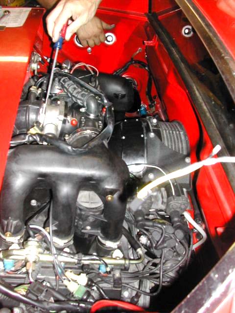
Passenger side, looking across.
* You can see I don't have a branch tee fitting on the plenum, I've used a short length of hose with a plastic tee fitting to substitute. Finally fixing this next week.
* Big washer under the coil strap - that's a fix for a flaw in the attachment to the sheet metal. Ugly but works.
* Shorty transistorized Bosch voltage regulator
* Bowlsby FI wiring harness
* Non-OEM hoses for the fuel evaporation fresh air supply and return
Passenger side, looking down
* Yes, those are the 50 year-old plastic fuel lines. Hopefully, to be replaced later this year.
* The red/black wires at the bottom are a permanent connection for my trickle charger
* Battery cover and acid mat
* Decel valve (vacuum limiter) in place and correctly plumbed. While this device is often though of as being solely for reduced emissions, it has a second purpose. When the throttle is closed while engine braking, vacuum in the intake manifold can approach 25 inHg, as compared to 10 to 15 inHg at idle. This vacuum is applied to the MPS, which means the full-load diaphragm in the MPS (the thing that cracks due to fatigue stress, and makes your MPS leaky) receives additional stress, leading to early failure. The decel valve limits manifold vacuum to 18 inHg, significantly reducing stress on the full-load diaphragm.
A lot of people with D-Jetronic remove the decel valve - I do not recommend it. The MPS is critical to the operation of your FI system, and a rebuilt unit is expensive.
Driver's side, looking across.
* Trickle charger cable again visible.
* Note the second cable attached to the battery ground point. This is a cable connected directly to the starter body to eliminate any ground drops.
* Trickle charger cable again visible.
* Note the second cable attached to the battery ground point. This is a cable connected directly to the starter body to eliminate any ground drops.
Driver's side, looking down.
Only thing of note here is hard to see. One of the cables going through the engine tin grommet is a 10 gauge ground wire that connects to the ground point in the engine compartment, and to the body of the alternator below. I figured out some time ago that the alternator bracket was the only way ground was being supplied to it. Adding a heavy ground wire eliminated a significant voltage drop here.
Only thing of note here is hard to see. One of the cables going through the engine tin grommet is a 10 gauge ground wire that connects to the ground point in the engine compartment, and to the body of the alternator below. I figured out some time ago that the alternator bracket was the only way ground was being supplied to it. Adding a heavy ground wire eliminated a significant voltage drop here.

Fantastic, great pic
Somehow, this all fits without any cutting ...

Pbanders, have you run a vacuum gauge while driving? My numbers are quite a bit different and was curious about that. 17-18 at idle warm, dragging down a hill, 23ish is common. Decel works great, full open by 18.5....
My engine bay looks like a 50 year old car. Yours looks brand new.
You can see my copper foil on the oil pressure sender, the extra ground to the shroud in yellow, and the cht sender wire being all ugly. Otherwise stock. And my aav bypass valve for troubleshooting. And the t for the in dash vacuum gauge
Click to view attachment

2.0
[quote name='pbanders' post='3003100' date='May 20 2022, 04:01 PM']
Passenger side, looking down
* Yes, those are the 50 year-old plastic fuel lines. Hopefully, to be replaced later this year.
No engine pic here. But yes time to replace the fuel lines to Stainless Steel fuel lines all the way to the fuel tank.
Passenger side, looking down
* Yes, those are the 50 year-old plastic fuel lines. Hopefully, to be replaced later this year.
No engine pic here. But yes time to replace the fuel lines to Stainless Steel fuel lines all the way to the fuel tank.
Wow, some impressive engine bays!
Work in progress
QUOTE(emerygt350 @ May 21 2022, 04:14 AM) 
Pbanders, have you run a vacuum gauge while driving? My numbers are quite a bit different and was curious about that. 17-18 at idle warm, dragging down a hill, 23ish is common. Decel works great, full open by 18.5....
My engine bay looks like a 50 year old car. Yours looks brand new.
You can see my copper foil on the oil pressure sender, the extra ground to the shroud in yellow, and the cht sender wire being all ugly. Otherwise stock. And my aav bypass valve for troubleshooting. And the t for the in dash vacuum gauge
Click to view attachment
I don't have a gauge, our numbers look reasonably similar to me. Will do a temporary gauge and check it out.
Is your fuel evaporation system present? Looks like you have the fresh air supply for it plumbed to your flashback trap.
Looks like a 73 throttle body, as you have the vacuum advance port.
What's the yellow two conductor wire at the bottom of the pic for?
Is that a fuel pressure gauge in the lower left corner?
QUOTE(KevinW @ May 21 2022, 06:13 AM)
Work in progress
Very impressive!
QUOTE(brant @ May 21 2022, 06:01 AM)
2.0
Super-clean, beautiful.
QUOTE(ClayPerrine @ May 21 2022, 04:25 AM)
Clay, what an I looking at here?
Like others have already mentioned: "originally" a 1.8.
Unlike others, there was a bit of cutting...
Unlike others, there was a bit of cutting...
QUOTE(brant @ May 21 2022, 09:01 AM)
2.0
As an engineer I love all the FI and the modern air cooled swaps.
But . . . the triple carbs just resonate with my soul.

Click to view attachment
Mine
QUOTE(tygaboy @ May 21 2022, 07:03 AM)
Like others have already mentioned: "originally" a 1.8.
Unlike others, there was a bit of cutting...
Awesome, thanks!
QUOTE(BillJ @ May 21 2022, 08:03 AM)
Mine
Beautiful.
Click to view attachment
Need a low profile breather can to drain to oil intake.
I see no oil residue in translucent lines. My head vents are connected together
Need a low profile breather can to drain to oil intake.
I see no oil residue in translucent lines. My head vents are connected together
QUOTE(barefoot @ May 21 2022, 12:05 PM)
Click to view attachment
Need a low profile breather can to drain to oil intake.
I see no oil residue in translucent lines. My head vents are connected together
Very clean install, great job. Where does the outlet hose from your catch can go to?
not as eye popping as the two previous 6s but stock has its place too.Click to view attachment

QUOTE(pbanders @ May 21 2022, 07:17 AM)
QUOTE(emerygt350 @ May 21 2022, 04:14 AM)
Pbanders, have you run a vacuum gauge while driving? My numbers are quite a bit different and was curious about that. 17-18 at idle warm, dragging down a hill, 23ish is common. Decel works great, full open by 18.5....
My engine bay looks like a 50 year old car. Yours looks brand new.
You can see my copper foil on the oil pressure sender, the extra ground to the shroud in yellow, and the cht sender wire being all ugly. Otherwise stock. And my aav bypass valve for troubleshooting. And the t for the in dash vacuum gauge
Click to view attachment
I don't have a gauge, our numbers look reasonably similar to me. Will do a temporary gauge and check it out.
Is your fuel evaporation system present? Looks like you have the fresh air supply for it plumbed to your flashback trap.
Looks like a 73 throttle body, as you have the vacuum advance port.
What's the yellow two conductor wire at the bottom of the pic for?
Is that a fuel pressure gauge in the lower left corner?
It would be nice to know about the vac.
I believe I have it all going correctly. Counter clockwise I have decel, EVAP, aav, then pcv (fresh air in to the flashback trap). Are the ports on the air cleaner different?
The ugly yellow is for the cht gauge.
And yes, fuel pressure gauge a very helpful addition.
QUOTE(emerygt350 @ May 21 2022, 08:33 PM)
QUOTE(pbanders @ May 21 2022, 07:17 AM)
QUOTE(emerygt350 @ May 21 2022, 04:14 AM)
Pbanders, have you run a vacuum gauge while driving? My numbers are quite a bit different and was curious about that. 17-18 at idle warm, dragging down a hill, 23ish is common. Decel works great, full open by 18.5....
My engine bay looks like a 50 year old car. Yours looks brand new.
You can see my copper foil on the oil pressure sender, the extra ground to the shroud in yellow, and the cht sender wire being all ugly. Otherwise stock. And my aav bypass valve for troubleshooting. And the t for the in dash vacuum gauge
Click to view attachment
I don't have a gauge, our numbers look reasonably similar to me. Will do a temporary gauge and check it out.
Is your fuel evaporation system present? Looks like you have the fresh air supply for it plumbed to your flashback trap.
Looks like a 73 throttle body, as you have the vacuum advance port.
What's the yellow two conductor wire at the bottom of the pic for?
Is that a fuel pressure gauge in the lower left corner?
It would be nice to know about the vac.
I believe I have it all going correctly. Counter clockwise I have decel, EVAP, aav, then pcv (fresh air in to the flashback trap). Are the ports on the air cleaner different?
The ugly yellow is for the cht gauge.
And yes, fuel pressure gauge a very helpful addition.
OK, I see what you're doing. You have it (CCW) Decel/Evap/AAR/Flashback. It's normally Decel/Flashback/AAR/Evap. Putting the Evap where you have it makes it cross in front of the engine fan, probably OK but not as Porsche did it.
As you have your Decel in place, but it's not visible in the pic, which port are you running that hose from the airbox to? The port on the end, or the port on the side? You may not be aware of this, but most of the hose diagrams are wrong when it comes to the Decel valve connections. Vacuum should be connected to the 5 mm control port (the one with the thread and nut) and to the 9 mm port on the opposite end, and fresh air from the air box should be connected to the 9 mm port on the side. Most diagrams have the connections to the two 9 mm ports reversed. If you connect it that way, the valve cannot work, because there's vacuum on both sides of the internal diaphragm, and it never moves, no matter what the vacuum is in the intake plenum.
A different view!Click to view attachment
I'll throw this in here - took it recently while working through the oil pressure gauge block install. Don't judge that too harshly - work in progress. 74 2.0
Click to view attachment
Click to view attachment
Mixin it up with some stock goodness
QUOTE(pbanders @ May 21 2022, 08:33 AM)
QUOTE(ClayPerrine @ May 21 2022, 04:25 AM)
Clay, what an I looking at here?
That is a 4.0L 964 motor in a 914. LN Engineering Cylinders, JE Pistons, Pauter Rods, 993RS spec cams, and a Steve Wong Motronic chip. All tied to the ground through a cable shifted Cayman 6 speed.
That picture was taken right after I put the motor in the car.
Caly
Yowzer!!!
QUOTE(JeffBowlsby @ May 22 2022, 09:47 AM)
Mixin it up with some stock goodness
Nice!
QUOTE(pbanders @ May 22 2022, 07:18 AM)
[]
OK, I see what you're doing. You have it (CCW) Decel/Evap/AAR/Flashback. It's normally Decel/Flashback/AAR/Evap. Putting the Evap where you have it makes it cross in front of the engine fan, probably OK but not as Porsche did it.
As you have your Decel in place, but it's not visible in the pic, which port are you running that hose from the airbox to? The port on the end, or the port on the side? You may not be aware of this, but most of the hose diagrams are wrong when it comes to the Decel valve connections. Vacuum should be connected to the 5 mm control port (the one with the thread and nut) and to the 9 mm port on the opposite end, and fresh air from the air box should be connected to the 9 mm port on the side. Most diagrams have the connections to the two 9 mm ports reversed. If you connect it that way, the valve cannot work, because there's vacuum on both sides of the internal diaphragm, and it never moves, no matter what the vacuum is in the intake plenum.
Interesting! When I get back to the states I will double check that! It's been a while so I can't remember if I just followed the diagram or used common sense.
Nice to know about the EVAP. I plumbed that based on the length of hose available. Figured there was a reason for all of that hose but I guess it could have been messed with.
[quote name='emerygt350' date='May 23 2022, 06:05 AM' post='3003602']
[quote name='pbanders' post='3003407' date='May 22 2022, 07:18 AM']
[]. Vacuum should be connected to the 5 mm control port (the one with the thread and nut) and to the 9 mm port on the opposite end, and fresh air from the air box should be connected to the 9 mm port on the side. Most diagrams have the connections to the two 9 mm ports reversed. If you connect it that way, the valve cannot work, because there's vacuum on both sides of the internal diaphragm, and it never moves, no matter what the vacuum is in the intake plenum.
[/quote]
Just to be clear. Vacuum goes to the small port facing the passenger, that is what I have for sure. And vacuum also to the posterior port facing the rear of the car? Wouldn't that create vacuum on both sides? I don't really know what the construction of the valve looks like internally but it just feels like it would...
[quote name='emerygt350' date='May 23 2022, 05:19 AM' post='3003604']
[quote name='emerygt350' date='May 23 2022, 06:05 AM' post='3003602']
[quote name='pbanders' post='3003407' date='May 22 2022, 07:18 AM']
[]. Vacuum should be connected to the 5 mm control port (the one with the thread and nut) and to the 9 mm port on the opposite end, and fresh air from the air box should be connected to the 9 mm port on the side. Most diagrams have the connections to the two 9 mm ports reversed. If you connect it that way, the valve cannot work, because there's vacuum on both sides of the internal diaphragm, and it never moves, no matter what the vacuum is in the intake plenum.
[/quote]
Just to be clear. Vacuum goes to the small port facing the passenger, that is what I have for sure. And vacuum also to the posterior port facing the rear of the car? Wouldn't that create vacuum on both sides? I don't really know what the construction of the valve looks like internally but it just feels like it would...
[/quote]
Below is a diagram of the internals of the decel valve. As you can see, it's two chambers separated by a flexible diaphragm, and a valve covering the end port.
If vacuum is applied to both the control and the side port, and the end port is connected to atmospheric pressure, the diaphragm has the same pressure on both sides and will never move, no matter what pressure is applied. This configuration is the way many of the hose diagrams show.
Now, swap the hoses on the side and end port, so that the side port is connected to atmospheric pressure and the end port to vacuum. If P1 is at atmospheric pressure and P2 is at a vacuum below the setpoint, the tension spring will hold the valve shut. Once P2 is at a high enough vacuum to overcome the spring tension, the valve opens, and P1 now cannot exceed the setpoint vacuum, limiting the vacuum - which is why the device is also called a vacuum limiter.
BTW, this is not conjecture, I have tested it in both configurations using my hand vacuum pump and hoses and tee connectors to apply vacuum to the ports. You can test it yourself, this is how it works.

Just another 3.6 swap. 
]
Just switched the decel to the right configuration, max vacuum on drag is 23 lbs. I hooked up my vac pump while the car was running and noticed it doesn't really affect engine speed untill maybe 21 pounds even though bench test had it opening at 18.5. anyone try it on the motor? Wondering if I should adjust that ..
Just switched the decel to the right configuration, max vacuum on drag is 23 lbs. I hooked up my vac pump while the car was running and noticed it doesn't really affect engine speed untill maybe 21 pounds even though bench test had it opening at 18.5. anyone try it on the motor? Wondering if I should adjust that ..
Click to view attachment
I’ve got a 2.0L with duel webers in a 1970.
Looks like the tops of the air filters could use a clean.
-Lance
I’ve got a 2.0L with duel webers in a 1970.
Looks like the tops of the air filters could use a clean.
-Lance
QUOTE(KevinW @ May 21 2022, 06:13 AM)
Work in progress
I might try this throttle linkage setup for my build when I get to this point... I like how simple it is. Just wonder if the cable can still operate smoothly in a long/bent configuration.
@tygaboy - Hey that fits remarkably well. 
[quote name='pbanders' date='May 23 2022, 07:18 AM' post='3003614']
[quote name='emerygt350' date='May 23 2022, 05:19 AM' post='3003604']
[quote name='emerygt350' date='May 23 2022, 06:05 AM' post='3003602']
[quote name='pbanders' post='3003407' date='May 22 2022, 07:18 AM']
[]. Vacuum should be connected to the 5 mm control port (the one with the thread and nut) and to the 9 mm port on the opposite end, and fresh air from the air box should be connected to the 9 mm port on the side. Most diagrams have the connections to the two 9 mm ports reversed. If you connect it that way, the valve cannot work, because there's vacuum on both sides of the internal diaphragm, and it never moves, no matter what the vacuum is in the intake plenum.
[/quote]
Just to be clear. Vacuum goes to the small port facing the passenger, that is what I have for sure. And vacuum also to the posterior port facing the rear of the car? Wouldn't that create vacuum on both sides? I don't really know what the construction of the valve looks like internally but it just feels like it would...
[/quote]
Below is a diagram of the internals of the decel valve. As you can see, it's two chambers separated by a flexible diaphragm, and a valve covering the end port.
If vacuum is applied to both the control and the side port, and the end port is connected to atmospheric pressure, the diaphragm has the same pressure on both sides and will never move, no matter what pressure is applied. This configuration is the way many of the hose diagrams show.
Now, swap the hoses on the side and end port, so that the side port is connected to atmospheric pressure and the end port to vacuum. If P1 is at atmospheric pressure and P2 is at a vacuum below the setpoint, the tension spring will hold the valve shut. Once P2 is at a high enough vacuum to overcome the spring tension, the valve opens, and P1 now cannot exceed the setpoint vacuum, limiting the vacuum - which is why the device is also called a vacuum limiter.
BTW, this is not conjecture, I have tested it in both configurations using my hand vacuum pump and hoses and tee connectors to apply vacuum to the ports. You can test it yourself, this is how it works.
[/quote]
you are correct @pbanders
i have seen hose diagrams floating around which have the wrong connections to the ports on the decel valve for 1.8 L-Jets. amongst other hose errors.
even the diagrams in the factory workshop manual covering D Jet are questionable.
often the decel valve isn't even drawn as an accurate representation with regard to ports.
you can find a reliable configuration layout in the parts catalogue.
OK, here's my '74's engine bay. This is a 2375 with dual 44 IDFs and top-mounted A/C Compressor. Thinking about installing a bus-bar for all my "direct to battery" connections.
Click to view attachment
Click to view attachment
That's very clean and a nice small compressor.
This is a "lo-fi" version of our main content. To view the full version with more information, formatting and images, please click here.