|
|

|
Porsche, and the Porsche crest are registered trademarks of Dr. Ing. h.c. F. Porsche AG.
This site is not affiliated with Porsche in any way. Its only purpose is to provide an online forum for car enthusiasts. All other trademarks are property of their respective owners. |
|
|
  |
| bdstone914 |
 Mar 29 2019, 04:34 PM Mar 29 2019, 04:34 PM
Post
#41
|
|
bdstone914     Group: Members Posts: 4,735 Joined: 8-November 03 From: Riverside CA Member No.: 1,319 |
I think it was the No high beams you were discussing. The relay requires more load to trigger to high, the additional wire in resistors fix that. Who would think not drawing current on the headlights could be a problem. @Chi-town @mikey914 Dylan, Yes exact same problem we discussed. Low beam on, turn on fogs and high beams come on. Common in LED conversions. Many U tube videos showing how to install the resistor of circuits like turn signal. Affect many vehicles. Mark, Who would have thought low resistance was a problem ? About everyone on this thread including me. |
| Spoke |
 Mar 29 2019, 07:18 PM Mar 29 2019, 07:18 PM
Post
#42
|
|
Jerry      Group: Members Posts: 7,104 Joined: 29-October 04 From: Allentown, PA Member No.: 3,031 Region Association: None 
|
Seems when changing to LEDs one should expect issues and then be pleasantly surprised if no issues arise.
For LED turnsignals likely the OEM flasher relay will need replaced. It's an absolute must with the 911 as its OEM flasher will hyperflash even if one turnsignal front or rear is replaced with LEDs. For 911's with cruise control, if all brake lights are changed to LEDs, the CC will not engage. Turns out the CC ECU dumps about 7ma into the brake lights. With incandescent bulbs, this is not a problem. With LED brake lights, the light will glow dimly as LEDs will light up even with a tenth of a milliamp. The 911 CC ECU monitors the voltage on the brake lights. I couldn't put enough ballast resistance on the boards to allow the CC to function properly. What solved this was the pigtail below with two 12 ohm 50W resistors in parallel. One 6 ohm 50W resistor could have been used but it would get too hot if one engaged the brakes for a long period of time. This pigtail is inserted in series with the brake light switch on the brake master cylinder. Attached thumbnail(s) 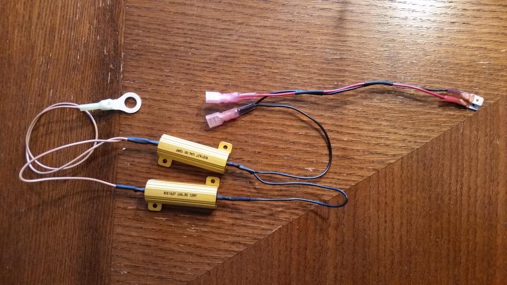 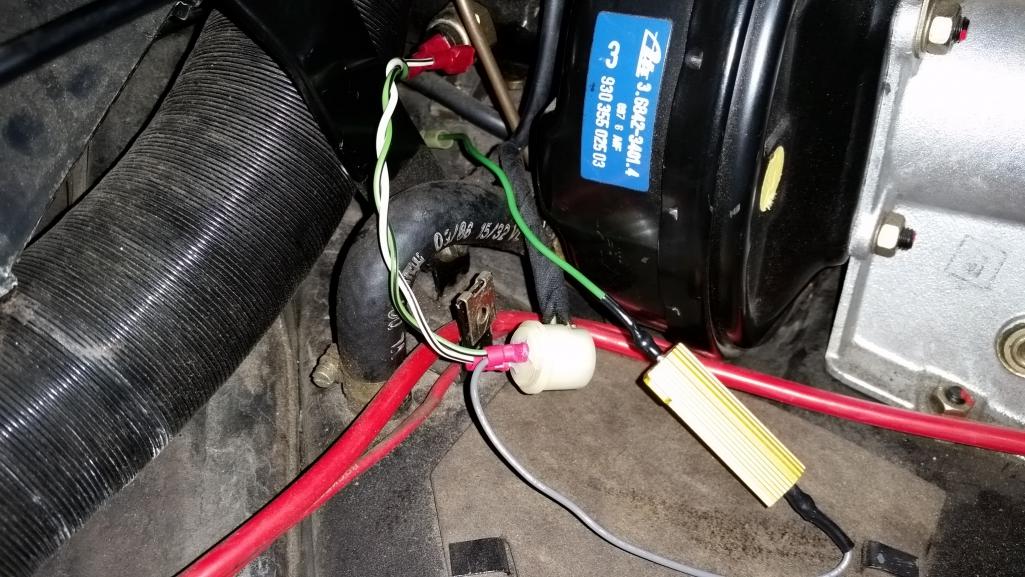
|
| Matty900 |
 Mar 29 2019, 11:19 PM Mar 29 2019, 11:19 PM
Post
#43
|
|
Senior Member    Group: Members Posts: 1,284 Joined: 21-February 15 From: Oregon Member No.: 18,454 Region Association: Pacific Northwest |
The issue is the led is not pulling enough load. When you add a resistor it solves the problem. We have them and I tested them to confirm that it solves the problem. I have not had the chance to finalize the install instructions and Bruce has been trying to help me on this. The only questions I have are where is the best place to mount it. One thought is to mount it to the headlight housing on the opposite side of the bar as far away from the metals pop up cover. The reason being, it's a resistor and will get warm. I don't want it next to the paint. The pros of putting it hear is that it is out of sight. The con's if you drive in the rain this can become a wet area so your connections need to be properly weather proofed (good barrel connectors and heat shrink.)
The 2nd photo is only showing you what wires you need to tie in to, not where to do so. However, you can put the wires in here and plug the light in to test and make sure this resolves your issue. Spoke, Chi-town, Mike B where would you suggest mounting this? Attached thumbnail(s) 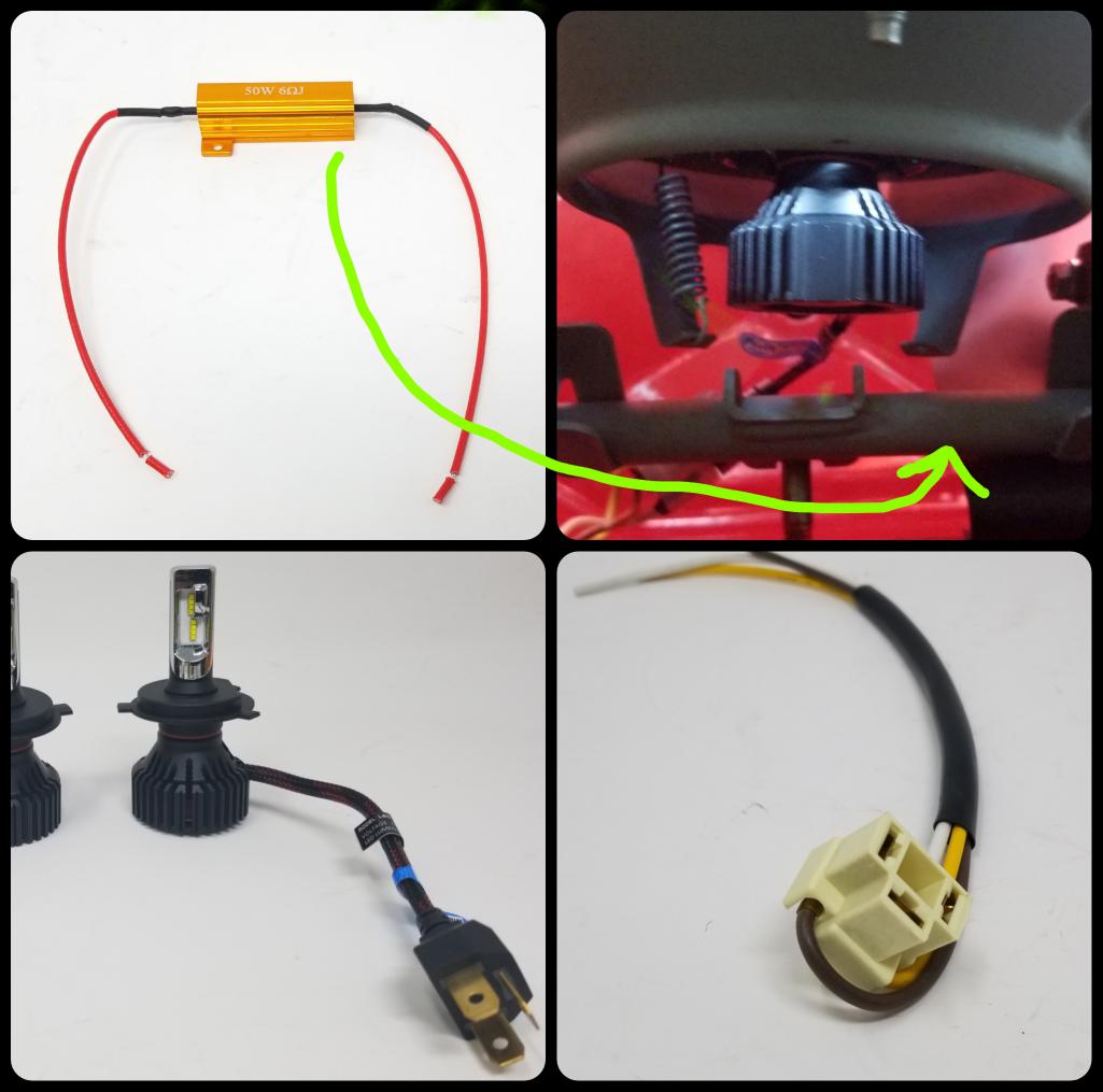 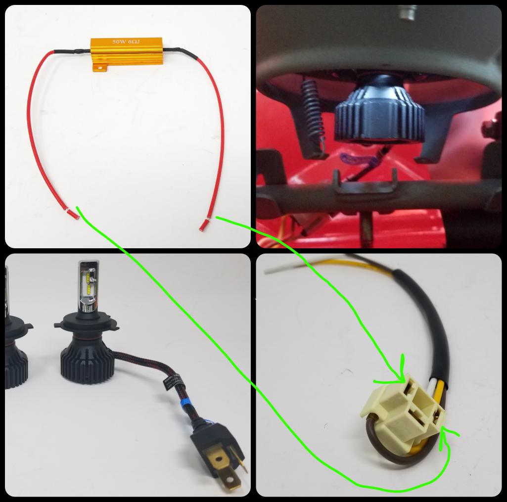
|
| Spoke |
 Mar 30 2019, 07:46 AM Mar 30 2019, 07:46 AM
Post
#44
|
|
Jerry      Group: Members Posts: 7,104 Joined: 29-October 04 From: Allentown, PA Member No.: 3,031 Region Association: None 
|
...it's a resistor and will get warm. Spoke, Chi-town, Mike B where would you suggest mounting this? Does this go across the high beam or low beam LED? I assume the resistor will have full battery voltage (14V) on it when energized. From the picture it looks like its a 6 ohm, 50W resistor. With a 6 ohm resistor with 14V across it, it will be burning 32W (V*V/R). According to Vishay's TMC0506R000FE02 6 ohm, 50W resistor specs, free air mounting of the resistor allows only 40% of the power dissipation or 20W. To burn 32W reliably the resistor should be mounted on a metal surface like an inner fender likely using the tabs to mount it with screws. A metal brace or bracket might work as well as long as there is solid contact between the brace and the bottom of the resistor. All paint should be scraped off of the brace/bracket/fender for good thermal conduction. This derating in power dissipation in free air is why I ended up with two 12 ohm 50W resistors for the brake light ballast. I started with one 6 ohm 50W resistor but realized this would exceed the manufacturer's recommended free air power dissipation. The resistors for the brake ballast can be tie wrapped onto a brace near the brake MC. Can you use a higher ohm resistor like 12 ohm? If so, then the power dissipation would be 16W and would be consistent with the manufacturer's guidelines for free air mounting. I think you only need to be able to trick the high/low beam switch and provide a low enough resistance to energize the fog light relay. Interestingly these resistors are recommended as ballast resistors for turnsignals when LEDs are used. In this case, they can be used in free air since the turnsignal is on only 1/2 the time thus the overall power dissipation is 32/2 which is less than 20W (40%). |
| FlacaProductions |
 Mar 30 2019, 09:10 AM Mar 30 2019, 09:10 AM
Post
#45
|
|
Senior Member    Group: Members Posts: 1,845 Joined: 24-November 17 From: LA Member No.: 21,628 Region Association: Southern California 
|
Sounds like this is the truth.....
QUOTE Seems when changing to LEDs one should expect issues and then be pleasantly surprised if no issues arise. |
| Chi-town |
 Mar 30 2019, 10:56 PM Mar 30 2019, 10:56 PM
Post
#46
|
|
Senior Member    Group: Members Posts: 851 Joined: 31-August 18 From: Disneyland Member No.: 22,446 Region Association: Southern California |
Could you separate the ground for the fog relay from the high beam circuit?
Give it an actual ground and turn them off manually when using high beams? |
| Spoke |
 Mar 31 2019, 06:37 AM Mar 31 2019, 06:37 AM
Post
#47
|
|
Jerry      Group: Members Posts: 7,104 Joined: 29-October 04 From: Allentown, PA Member No.: 3,031 Region Association: None 
|
Could you separate the ground for the fog relay from the high beam circuit? Give it an actual ground and turn them off manually when using high beams? Separating the ground for the fog relay would negate the need for the fog light relay to have a ballast resistor. It would make the fog light independent of the high/low beam. Here's how the '74 914 foglights are connected. Notice the white/blue wire from the fog light relay to the top of fuses 1 and 2. Likely this wire is connected at the fuse panel and able to be easily disconnected. Then make a short pigtail with a male spade on one side and a ring terminal on the other side. Connect the male spade to the white/blue wire and the the ring terminal to a nearby chassis bolt. 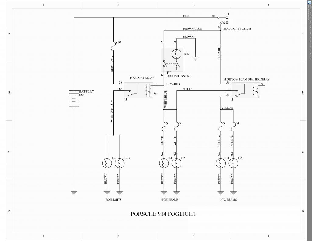 |
| Mikey914 |
 Mar 31 2019, 12:52 PM Mar 31 2019, 12:52 PM
Post
#48
|
|
The rubber man           Group: Members Posts: 12,741 Joined: 27-December 04 From: Hillsboro, OR Member No.: 3,348 Region Association: None 
|
The load resistor needs to be on the low beam, to trigger the relay.
|
| Chi-town |
 Apr 1 2019, 02:11 PM Apr 1 2019, 02:11 PM
Post
#49
|
|
Senior Member    Group: Members Posts: 851 Joined: 31-August 18 From: Disneyland Member No.: 22,446 Region Association: Southern California |
|
| Spoke |
 Apr 1 2019, 04:00 PM Apr 1 2019, 04:00 PM
Post
#50
|
|
Jerry      Group: Members Posts: 7,104 Joined: 29-October 04 From: Allentown, PA Member No.: 3,031 Region Association: None 
|
Easiest way It could be so that this wire is found on the lugs on the fuse panel for fuse 1 or 2. Easily removed and with a pigtail with male spade on one side and ring terminal on the other side, the modification "should" be an easy update. The fogs would be on then with low or high beam. Talking to Bruce today, I realized my 930 with LED headlights has the same connections as the 914. I haven't tried the foglights with the LED headlights to see if they still work. Will have to try it this weekend. |
| bdstone914 |
 Apr 2 2019, 08:43 AM Apr 2 2019, 08:43 AM
Post
#51
|
|
bdstone914     Group: Members Posts: 4,735 Joined: 8-November 03 From: Riverside CA Member No.: 1,319 |
Easiest way It could be so that this wire is found on the lugs on the fuse panel for fuse 1 or 2. Easily removed and with a pigtail with male spade on one side and ring terminal on the other side, the modification "should" be an easy update. The fogs would be on then with low or high beam. Talking to Bruce today, I realized my 930 with LED headlights has the same connections as the 914. I haven't tried the foglights with the LED headlights to see if they still work. Will have to try it this weekend. @Chi-town @spoke @mikey914 @matty900 Dylan, ( Chi-town) Anxious to see if it works. Will be glad to help and document exactly how it it done. Bruce |
| Spoke |
 Apr 2 2019, 11:20 AM Apr 2 2019, 11:20 AM
Post
#52
|
|
Jerry      Group: Members Posts: 7,104 Joined: 29-October 04 From: Allentown, PA Member No.: 3,031 Region Association: None 
|
I may drop the fuse panel this weekend in my 914 to look for the white/blue foglight wire.
|
| bdstone914 |
 Apr 2 2019, 06:06 PM Apr 2 2019, 06:06 PM
Post
#53
|
|
bdstone914     Group: Members Posts: 4,735 Joined: 8-November 03 From: Riverside CA Member No.: 1,319 |
I may drop the fuse panel this weekend in my 914 to look for the white/blue foglight wire. @spoke @chi-town Dylan is going to try the same on a 914. I like the option of separating the operation of the dogs from the headlights. Still looking at best mounting for the load resitor. Here is where I think it should go. Thick metal and air flow when the lights are up. Attached thumbnail(s) 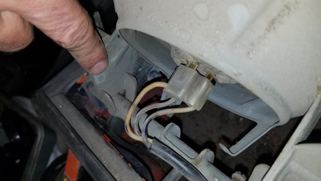
|
| Spoke |
 Apr 6 2019, 10:34 AM Apr 6 2019, 10:34 AM
Post
#54
|
|
Jerry      Group: Members Posts: 7,104 Joined: 29-October 04 From: Allentown, PA Member No.: 3,031 Region Association: None 
|
Talking to Bruce today, I realized my 930 with LED headlights has the same connections as the 914. I haven't tried the foglights with the LED headlights to see if they still work. Will have to try it this weekend. Confirmed today that the foglights on the 930 do work with low beams and turn off with high beams. It could be so that the LED headlights on the 930 have a different impedance than the ones on the 914. |
| orthobiz |
 Apr 6 2019, 11:00 AM Apr 6 2019, 11:00 AM
Post
#55
|
|
Senior Member    Group: Members Posts: 1,757 Joined: 8-January 07 From: Cadillac, Michigan Member No.: 7,438 Region Association: Upper MidWest 
|
I never posted my final solution. I had the fogs wired separately so no more hi beam/lo beam woes.
Paul |
| FlacaProductions |
 Apr 6 2019, 01:13 PM Apr 6 2019, 01:13 PM
Post
#56
|
|
Senior Member    Group: Members Posts: 1,845 Joined: 24-November 17 From: LA Member No.: 21,628 Region Association: Southern California 
|
separately? you mean direct and bypassing the interconnection/relay with the hi/lo switch?
|
| orthobiz |
 Apr 6 2019, 02:35 PM Apr 6 2019, 02:35 PM
Post
#57
|
|
Senior Member    Group: Members Posts: 1,757 Joined: 8-January 07 From: Cadillac, Michigan Member No.: 7,438 Region Association: Upper MidWest 
|
|
| drem914 |
 Apr 7 2019, 10:32 AM Apr 7 2019, 10:32 AM
Post
#58
|
|
Senior Member    Group: Members Posts: 1,051 Joined: 16-May 08 From: Trabuco Canyon, CA Member No.: 9,062 Region Association: Southern California 
|
|
| Spoke |
 Apr 7 2019, 09:48 PM Apr 7 2019, 09:48 PM
Post
#59
|
|
Jerry      Group: Members Posts: 7,104 Joined: 29-October 04 From: Allentown, PA Member No.: 3,031 Region Association: None 
|
I modified the headlight/foglight schematic to show where the foglight relay attaches to the high beam lights. Turns out the 914 is wired such that the white/blue wire from the foglight relay is connected directly to the spade connected to the high/low beam relay.
Attached thumbnail(s) 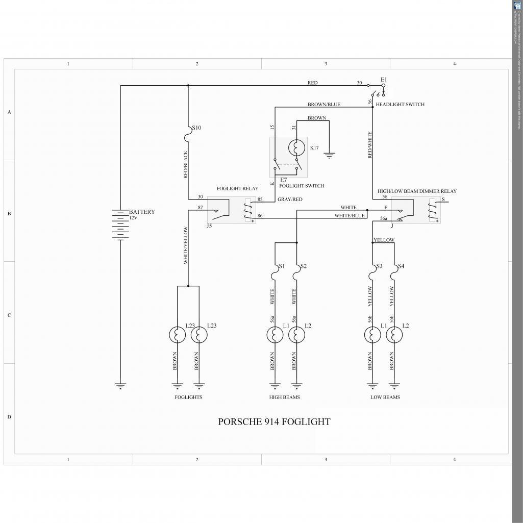
|
| Spoke |
 Apr 7 2019, 09:52 PM Apr 7 2019, 09:52 PM
Post
#60
|
|
Jerry      Group: Members Posts: 7,104 Joined: 29-October 04 From: Allentown, PA Member No.: 3,031 Region Association: None 
|
I decided to rewire the foglight to be independent of the high beams. Disconnected the battery negative cable and dropped the fuse panel.
The high/low beam relay is shown on the right side of the panel. The foglight wire is the white/blue wire. This wire will be cut and tied to ground. Attached thumbnail(s) 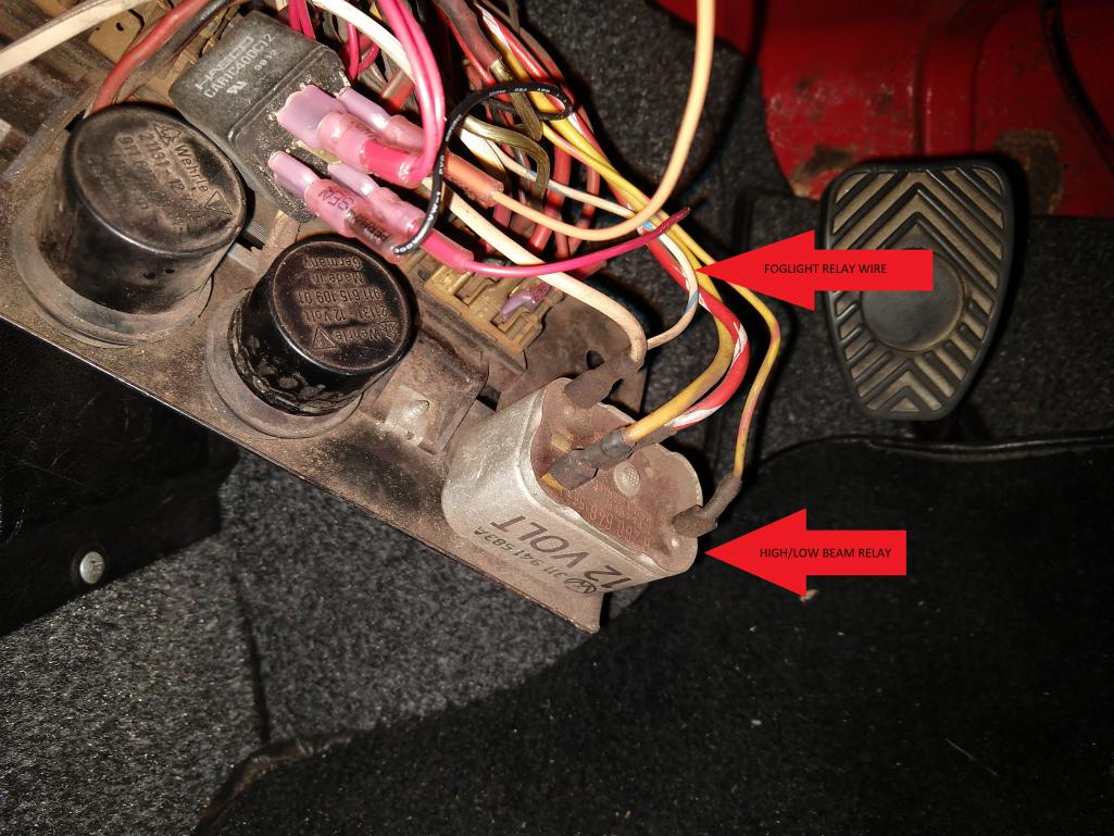
|
  |
1 User(s) are reading this topic (1 Guests and 0 Anonymous Users)
0 Members:

|
Lo-Fi Version | Time is now: 27th December 2024 - 07:43 AM |
Invision Power Board
v9.1.4 © 2024 IPS, Inc.


