|
|
|
Porsche, and the Porsche crest are registered trademarks of Dr. Ing. h.c. F. Porsche AG.
This site is not affiliated with Porsche in any way. Its only purpose is to provide an online forum for car enthusiasts. All other trademarks are property of their respective owners. |
|
|

  |

| Jeff Hail |
 Feb 17 2008, 06:44 PM Feb 17 2008, 06:44 PM
Post
#181
|
|
Senior Member  Group: Members Posts: 1,141 Joined: 3-May 07 From: LA/ CA Member No.: 7,712 |
Lets make some Sill Triangles
Made 2 templates. The first one is actual size after the bends (silhouette) of the mounted original. The second is 3/8 larger all the way around. Cut out the sheetmetal using the larger template and then trace the smaller (silhouette) template onto the cutouts. Then drill the holes. I am making right and left sides. Make some relief cuts so the bends don't buckle the flat area's. I tacked some really small welds where the sill plate doglegs over the bracket for strength. These were the tools used in the process and a metal scroll saw to make the cutouts . Finished triangle next to the original. Attached image(s) 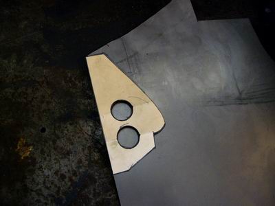 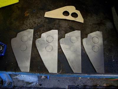 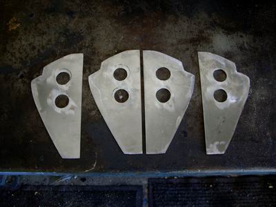 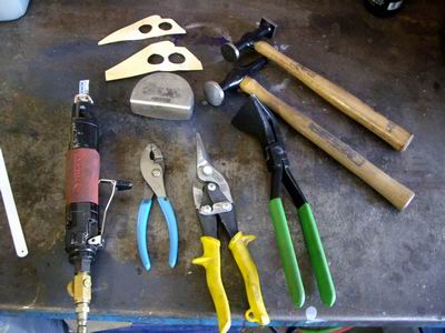 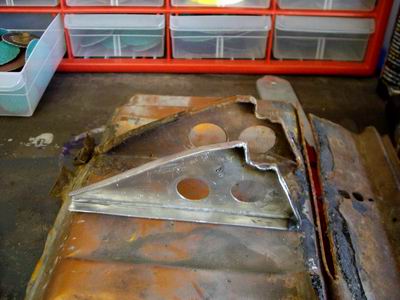
|
   |

 
|
| Jeff Hail |
Feb 17 2008, 06:46 PM
Post
#182
|
|
Senior Member Group: Members Posts: 1,141 Joined: 3-May 07 From: LA/ CA Member No.: 7,712 |
Primed set of 4 right and left side triangles.......
Attached image(s) 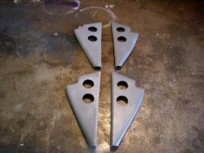
|
|
|
|
| watsonrx13 |
Feb 18 2008, 05:58 AM
Post
#183
|
|
Advanced Member Group: Members Posts: 2,735 Joined: 18-February 03 From: Plant City, FL Member No.: 312 Region Association: South East States |
Jeff, very nice job on the triangles. BTW, what gauge metal did you use?
-- Rob |
|
|
|
| Jeff Hail |
Feb 18 2008, 09:55 AM
Post
#184
|
|
Senior Member Group: Members Posts: 1,141 Joined: 3-May 07 From: LA/ CA Member No.: 7,712 |
QUOTE(watsonrx13 @ Feb 18 2008, 03:58 AM)  Jeff, very nice job on the triangles. BTW, what gauge metal did you use? -- Rob 18 gauge - Factory used a metric equivalent of 17. |
|
|
|
| Wes V |
Feb 18 2008, 07:35 PM
Post
#185
|
|
Member Group: Members Posts: 482 Joined: 11-October 07 From: Los angeles Member No.: 8,211 |
Jeff;
I just wanted to say thanks again for the sketch of your working platform. I just had 60 feet of steel delivered so I can build my own. Wes |
|
|
|
| Jeff Hail |
Feb 18 2008, 11:13 PM
Post
#186
|
|
Senior Member Group: Members Posts: 1,141 Joined: 3-May 07 From: LA/ CA Member No.: 7,712 |
QUOTE(Wes V @ Feb 18 2008, 05:35 PM) Jeff; I just wanted to say thanks again for the sketch of your working platform. I just had 60 feet of steel delivered so I can build my own. Wes Even know its thick metal weld slow. Start square -end square. Tack the four sides of the frame together first then weld the seams and corners. This way if it goes sideways you can break one of the tacks to adjust. If you have a couple of buddys doing nothing have them stand on the frame with backs to you while you are welding to keep if from distorting. If not sandbags work. If the main frame starts lifting a corner stop welding, flip the frame over and let it cool. Then weld the legs and crossbars. The diagonal leg supports will need to welded very slow in one or two inch bursts. If you weld too fast it will draw the crossbars up under heat and the rack will rock on 3 legs. You will have enough left over to use as crossbeams between the rack and car body. The three fixtures I made are secured at the front suspension crossmember mounting, rear just in front of the rear bumper and under the rear suspension ears. The ones under the passenger compartment are loose and can be removed for access as needed or slid forward/ backward as the floor for the most part is flat. Good luck Here is a better pictured unloaded Attached image(s) 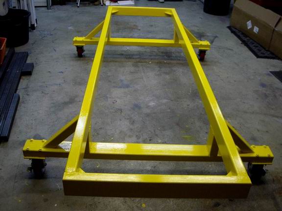
|
|
|
|
| Wes V |
Feb 19 2008, 09:30 AM
Post
#187
|
|
Member Group: Members Posts: 482 Joined: 11-October 07 From: Los angeles Member No.: 8,211 |
What you may find interesting is that I plan on using a contractors lazer level that throws a 360 degree line to ensure the main frame is true. (they cost something like 5 grand, but can be rented) I can set it in the middle of the main frame during set-up and welding to ensure it's in a true flat plane.
Once that's done, I'll weld on the legs and lower out-rigger (with wheels). When all is done and sitting on the garage floor, it will not be level (due to the slope of the garage floor, but will be a true flat plane to work off of. (hopefully I can do the main frame this week-end and will post up photos) Wes |
|
|
|
| Wes V |
Feb 22 2008, 07:52 PM
Post
#188
|
|
Member Group: Members Posts: 482 Joined: 11-October 07 From: Los angeles Member No.: 8,211 |
Here is a photo that shows how I ensured that the main platform frame is "true".
(IMG:http://www.performanceforum.com/wesvann/914a/plt.jpg) The item that is pointed at is a laser level that I borrowed from a contractor friend. When first turned on, it levels it's self and then throws out a level laser light (red) a full 360 degrees. The read line doesn't show in the photos, but having it hit the inside edge of the 2X4 tube, you can shim it up as required to make it level. I used a small framing square and put a piece of tape on it. You go to the "high" corner and place a mark on the tape where the laser light hits it. Then go to each other corner and shim it up to match. Once the frame is moved, it will not be level, but it will be "true". Wes |
|
|
|
| Jeff Hail |
Feb 22 2008, 08:03 PM
Post
#189
|
|
Senior Member Group: Members Posts: 1,141 Joined: 3-May 07 From: LA/ CA Member No.: 7,712 |
Good start Wes.
Lets see a new thread on the car to the left. I spy a AA outer wheelhouse in the background..You do know you are going to need a bigger garage? |
|
|
|
| Wes V |
Feb 22 2008, 08:19 PM
Post
#190
|
|
Member Group: Members Posts: 482 Joined: 11-October 07 From: Los angeles Member No.: 8,211 |
QUOTE(Jeff Hail @ Feb 22 2008, 06:03 PM) Good start Wes. Lets see a new thread on the car to the left. I spy a AA outer wheelhouse in the background..You do know you are going to need a bigger garage? The "clutter" shown in the photo is proof that a bigger garage would be nice. I've resisted doing a thread due to jumping around a lot on the project. I do have my own site where I'm documenting stuff. There isn't a lot there yet, but here is a link to the "flare-diary" that covers the front flares (I can't do the rears until rust repair is addressed. My flare-diary Wes |
|
|
|
| Jeff Hail |
Feb 23 2008, 08:10 PM
Post
#191
|
|
Senior Member Group: Members Posts: 1,141 Joined: 3-May 07 From: LA/ CA Member No.: 7,712 |
Another day with rain.
Cut and fitted the outer wheel house. Still need to do some cleanup grinding on the rear inner long (rail) before I can weld up the wheelhouse. In the last photo you will notice a hole on the wheelhouse (right center) above the two larger holes. This is the location of the factory pilot hole for placement of the outer suspension console. The AA part does not come with the hole and it needed to be transfered from the old part. If you are using stock consoles that hole is critical. Attached image(s) 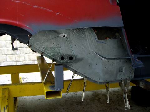 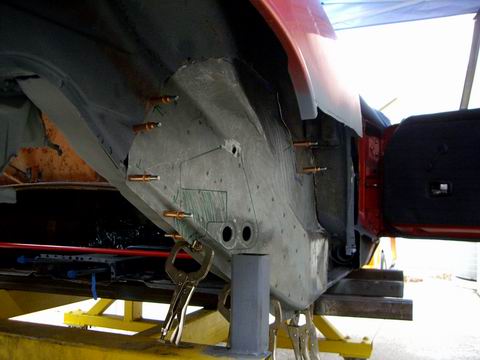 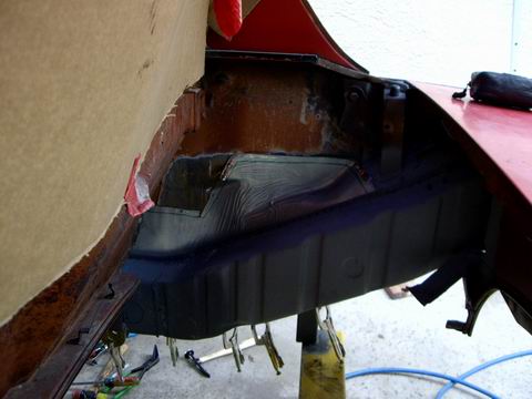 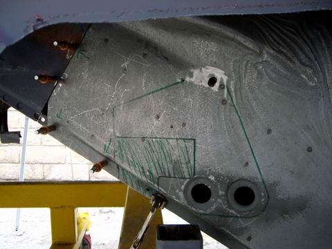
|
|
|
|
| Jeff Hail |
Feb 23 2008, 08:15 PM
Post
#192
|
|
Senior Member Group: Members Posts: 1,141 Joined: 3-May 07 From: LA/ CA Member No.: 7,712 |
Interior brace to keep the longs in check. It is adjustable and held with a few tacks on each inner long. Most projects would not require this.
Attached image(s) 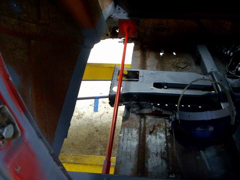
|
|
|
|
| Jeff Hail |
Feb 23 2008, 08:19 PM
Post
#193
|
|
Senior Member Group: Members Posts: 1,141 Joined: 3-May 07 From: LA/ CA Member No.: 7,712 |
Inner wheelhouse all the way to the door opening. Replacing it all the way forward is actually easier and reduces the chance of leaks in the future.
Last photo from below. The contour of the new part fits the original area pretty good. You might notice the new panel is fitted behind the original sheetmetal? The reason for this any water spray from spinning tires will of course find its way down via gravity. With no outside seam there will be no place for water to enter. Make sense? This will require more work inside the engine compartment but I am not building a show car. Attached image(s) 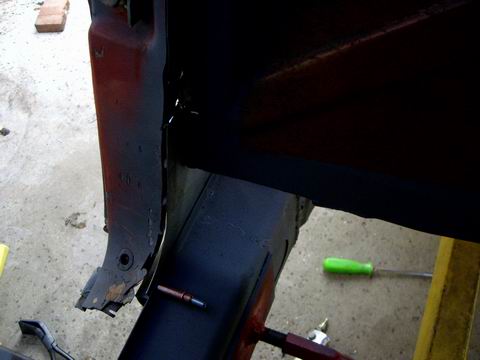 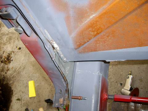 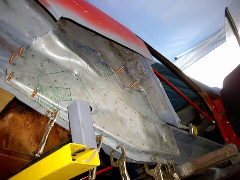
|
|
|
|
| Jeff Hail |
Feb 23 2008, 08:32 PM
Post
#194
|
|
Senior Member Group: Members Posts: 1,141 Joined: 3-May 07 From: LA/ CA Member No.: 7,712 |
Checked the fitment of the outer rocker and sill plate. It was nice to see these parts get some daylight.
Before I weld the wheelhouse up I need to install the J-Tube for the air delivery system and also the C-clamp for the silencer. Then I pulled it all apart again and sanded the wheelhouse for a coat of epoxy primer. Much easier to put some primer on the area's now that will be soon be a closed box. Attached image(s) 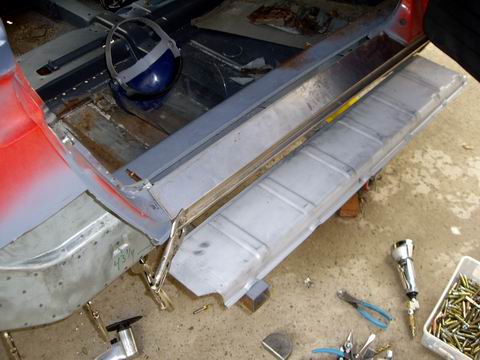 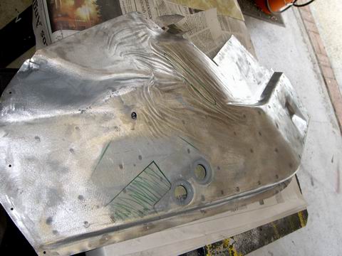 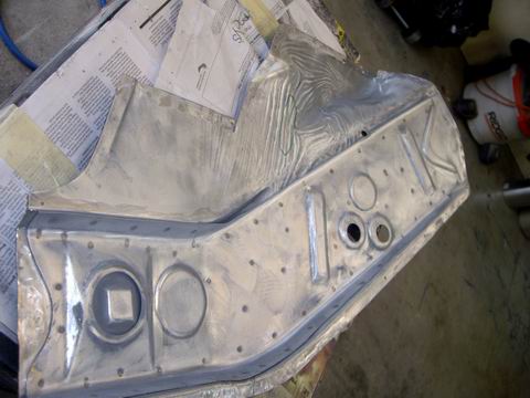
|
|
|
|
| Allan |
Feb 23 2008, 08:45 PM
Post
#195
|
|
Teenerless Weenie Group: Members Posts: 8,373 Joined: 5-July 04 From: Western Mesopotamia Member No.: 2,304 Region Association: Southern California |
I've been hanging out here for quite a while but for some reason never saw this thread.
I (IMG:style_emoticons/default/pray.gif) bow to you for the work and effort you have put into the car... |
|
|
|
| Jeff Hail |
Feb 28 2008, 07:04 PM
Post
#196
|
|
Senior Member Group: Members Posts: 1,141 Joined: 3-May 07 From: LA/ CA Member No.: 7,712 |
Trans is done
915, flipped ring gear for mid engine use. Aftermarket steel bearing retainer installed. G50 speedometer pickup (Hall sensor) installed on the right side plate. Gears: 1st AZ (11:35) 2nd HW (18:32) 3rd NT (23:29) 4th QQ (26:26) 5th ZD (38:30) Ring and pinion (8:31) Attached image(s) 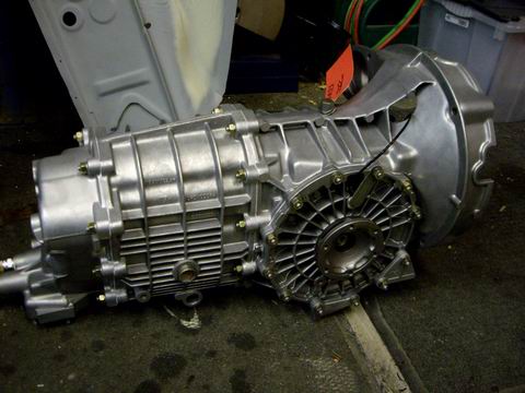 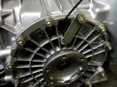
|
|
|
|
| Jeff Hail |
Mar 1 2008, 05:22 PM
Post
#197
|
|
Senior Member Group: Members Posts: 1,141 Joined: 3-May 07 From: LA/ CA Member No.: 7,712 |
Completed the metal prep on the outer rocker panels, inner firewall halves and floor.
Nice when everything is within arms reach. Have a thing for body hammers. Can you tell which one's get used the most? (50 year old Proto, all the rest are Martins) Time to prime. 2K epoxy primer, gotta have fresh air! Some of the primer will get ground off and/ or burned away on installation of these panels. It's a lot easier to have corrosion protection on before than trying to get it into little crevices and closed areas. Spray guns do not like curves and corners. Work smart not hard! Attached image(s) 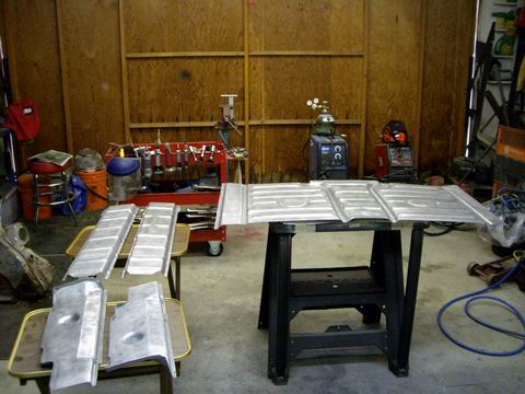 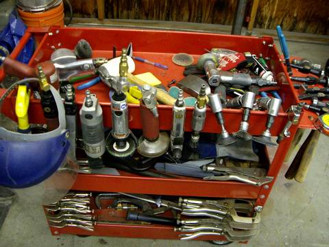 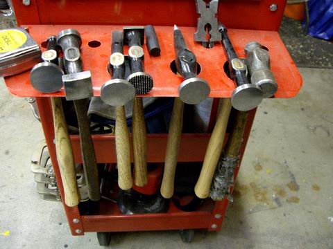 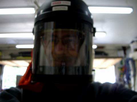
|
|
|
|
| Jeff Hail |
Mar 8 2008, 07:30 PM
Post
#198
|
|
Senior Member Group: Members Posts: 1,141 Joined: 3-May 07 From: LA/ CA Member No.: 7,712 |
Good day to burn some metal
Finished the metal work on the right rear rail/ long......Rt inner long prepped and epoxy primered last week. Sprayed some Wurth sprayable sealer inside before I close it all up. Put some extra sealer around the sleeves inside the long. Water creeps! Attached image(s) 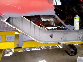 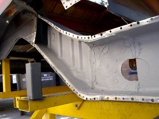
|
|
|
|
| Jeff Hail |
Mar 8 2008, 07:34 PM
Post
#199
|
|
Senior Member Group: Members Posts: 1,141 Joined: 3-May 07 From: LA/ CA Member No.: 7,712 |
Rt rear wheelhouse installed and welded!
The area at the inner rail joint is all plug welded. Various plug welds around the perimeter where the original wheelhouse meets the new then seam welded where the panels overlap. I discourage butt welding the inner wheelhouse for safety, structural and strength issues. Attached image(s) 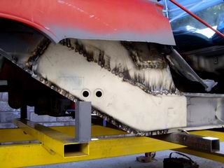
|
|
|
|
| Jeff Hail |
Mar 8 2008, 07:37 PM
Post
#200
|
|
Senior Member Group: Members Posts: 1,141 Joined: 3-May 07 From: LA/ CA Member No.: 7,712 |
All exterior welds ground down and finished.........
A coat of etching primer until tomorrow when I can grind/ finish the inside of the wheelhouse in the engine compartment. Attached image(s) 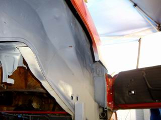 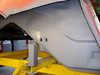 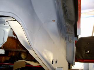
|
|
|
|
|
1 User(s) are reading this topic (1 Guests and 0 Anonymous Users)
0 Members:

|
Lo-Fi Version | Time is now: 5th July 2024 - 06:05 AM |
Invision Power Board
v9.1.4 © 2024 IPS, Inc.