|
|

|
Porsche, and the Porsche crest are registered trademarks of Dr. Ing. h.c. F. Porsche AG.
This site is not affiliated with Porsche in any way. Its only purpose is to provide an online forum for car enthusiasts. All other trademarks are property of their respective owners. |
|
|
  |
| jersey914 |
 Feb 23 2013, 08:54 AM Feb 23 2013, 08:54 AM
Post
#21
|
|
Member   Group: Members Posts: 161 Joined: 6-September 12 From: Marlton, NJ Member No.: 14,895 Region Association: North East States |
Cool conversion, way out of my league
|
| Bruce Hinds |
 Feb 24 2013, 10:16 AM Feb 24 2013, 10:16 AM
Post
#22
|
|
V-8 madness    Group: Members Posts: 748 Joined: 27-December 06 From: Port Orchard, WA Member No.: 7,391 Region Association: Pacific Northwest |
Holy smokes, you're a handy guy to have around the shop. Makes my work look shameful.
|
| andys |
 Feb 24 2013, 12:01 PM Feb 24 2013, 12:01 PM
Post
#23
|
|
Advanced Member     Group: Members Posts: 2,165 Joined: 21-May 03 From: Valencia, CA Member No.: 721 Region Association: None 
|
I mentioned earlier the need to move the firewall hump by 1 1/8" to get the water pump and accessory drive to clear. I wasn't sure how I'd deal with the intrusion into the cabin, but it seemed to be something I could tackle later in the build....I actually don't like proceeding without figuring everything out in advance (typical engineer!), but I though it was low risk.
The firewall hump only needed to be moved forward at the top. The crank pulley and alternator clearance at the bottom was adequate as is. What I did, was to cut the outline of what I needed, but not cut the bottom. I simply cut and inverted 'U', (attached at the bottom) and bent the it forward at the top. I made filler sections, and welded them in. Also, as all us 914 types do, an access panel was fabricated. Notice too, I had to make a sort of pie cut portion on the drivers side of the hump to clear the accessory drive serpentine belt. One additional area that required clearance, was the thermostat housing. The firewall needed a small hump there too, so I decided to make a removable hump thingy. I don't have a photo of the removable hump, so I'll describe it briefly. I only needed about 3/4" worth of hump, so I took a sheet metal pan I found at McMaster-Carr that was about 4" x 8" x 2" deep and cut it to 3/4" and welded a flange around its perifery. Not as easy as it sounds, since if you notice in the photos, there are stiffening ribs in the firewall which required the flange to change planes, so it was a bit involved. As with the access panel, I made this hump thing removable as well. To get the motor out of the car, the thermostat housing needs to be removed beforehand....things are that tight! Photos are out of order, and some show the result in its final painted form, but you get the idea. Attached thumbnail(s) 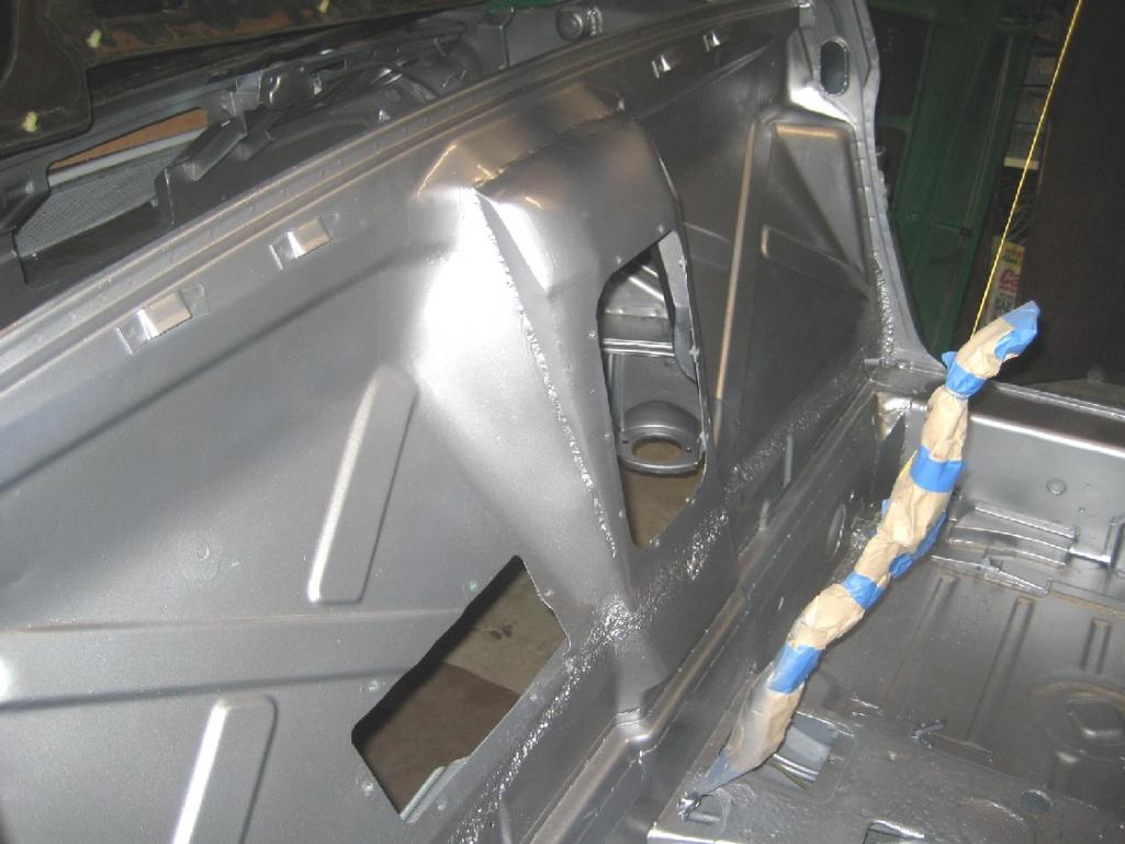 Attached image(s) 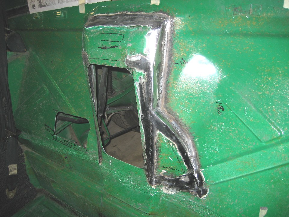 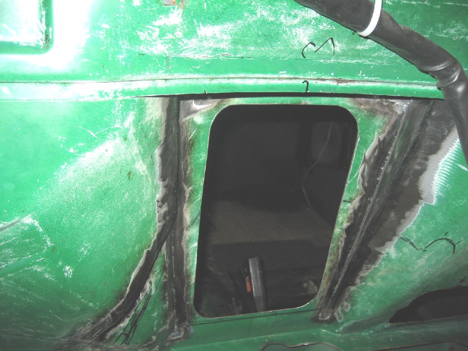 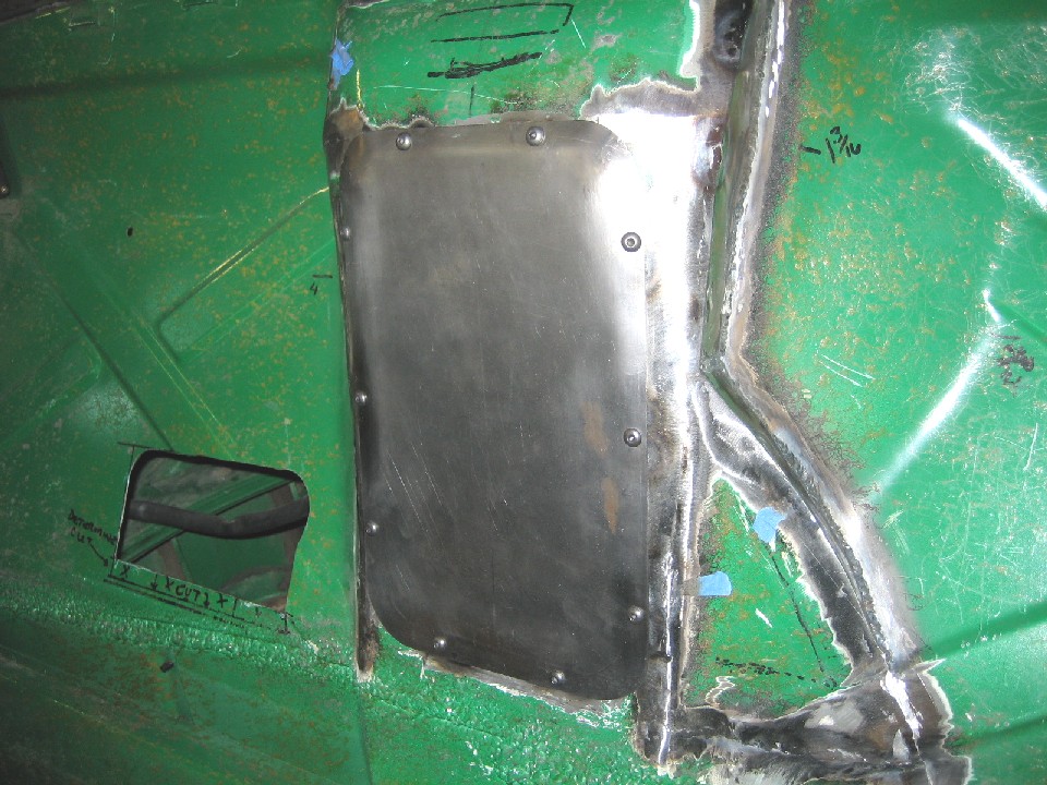 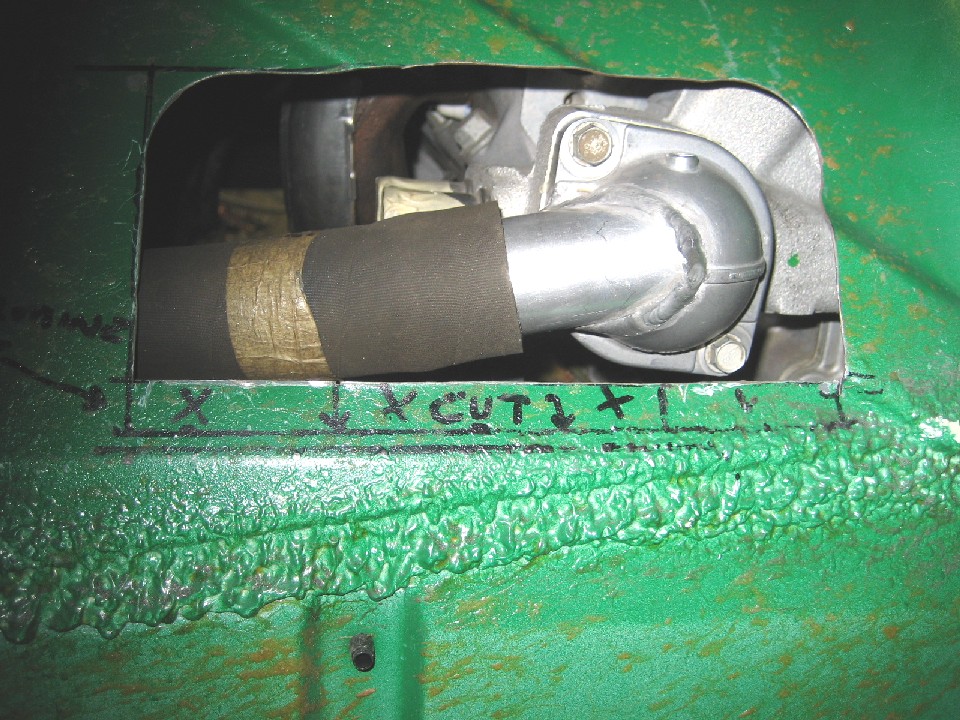 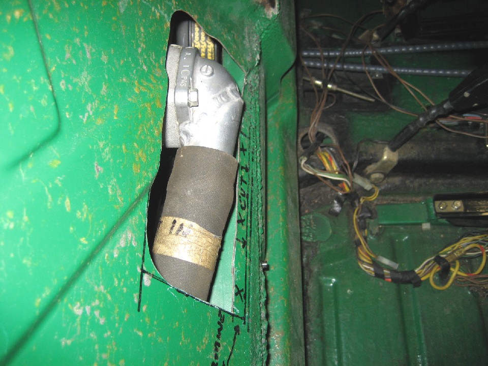 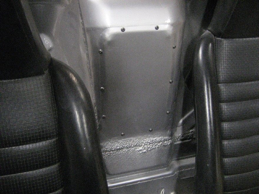
|
| messix |
 Feb 24 2013, 12:14 PM Feb 24 2013, 12:14 PM
Post
#24
|
|
AKA "CLUTCH KILLER"!      Group: Members Posts: 6,995 Joined: 14-April 05 From: between shit kickers and pinky lifters/ puget sound wa.north of Seattle south of Canada Member No.: 3,931 Region Association: Pacific Northwest |
have you left the tranny in the original location or have you moved it back a bit as in most v8 conversions? [half shafts canted back wards toward the tranny flanges]
|
| andys |
 Feb 24 2013, 12:16 PM Feb 24 2013, 12:16 PM
Post
#25
|
|
Advanced Member     Group: Members Posts: 2,165 Joined: 21-May 03 From: Valencia, CA Member No.: 721 Region Association: None 
|
|
| messix |
 Feb 24 2013, 12:24 PM Feb 24 2013, 12:24 PM
Post
#26
|
|
AKA "CLUTCH KILLER"!      Group: Members Posts: 6,995 Joined: 14-April 05 From: between shit kickers and pinky lifters/ puget sound wa.north of Seattle south of Canada Member No.: 3,931 Region Association: Pacific Northwest |
have you left the tranny in the original location or have you moved it back a bit as in most v8 conversions? [half shafts canted back wards toward the tranny flanges] I'll get to that in the next post or two.....stay tuned! Andys 10/4 just wondering why all the effort on the front side and firewall and if it was necessary.... i know stupid question.... (IMG:style_emoticons/default/slap.gif) |
| andys |
 Feb 24 2013, 05:32 PM Feb 24 2013, 05:32 PM
Post
#27
|
|
Advanced Member     Group: Members Posts: 2,165 Joined: 21-May 03 From: Valencia, CA Member No.: 721 Region Association: None 
|
Determining where the engine/transaxle assembly would best be located was driven by a couple of things. The motor has to fit in the hole (engine bay), and the transaxle drive flanges need to line up both front to back, and height wise to the wheel hubs at ride height. I was fortunate in that the 01E transaxle is shorter by 1" from the drive flange axis to the bellhousing than the 901. After adding in the adapter plate thickness stackup, I basically ended up with the drive flange axis very close to the original front to back location, and about 3/4" lower (the axles are angled slightly upward to meet the wheel hubs). I couldn't get the motor/transaxle any higher in the chassis, as the bellhousing would run into the trunk floor at a point where I prefered not to cut it due to structural concerns. The amount of axle angularity was acceptable to me.
With that info at hand, I set about designing the mounting scheme. What I decided on, was a cradle arrangement that would allow me to R&R the engine transaxle as a unit. You'll notice in the photo where the engine/transaxle is on the jack, that I fabricated a temporary engine mount bar so that I could experiment with the exact location. First, I had to fab a set of motor mount pedestals, since those neat aluminum Vette motor ones interfered with the AC compressor, as mentioned earlier. I decided on using the stock Vette hydro-elastic mounts. Being close to the header flanges, I decided to make some heat shields to guard against damage. I found some stainless cannisters at WalMart, cut them down, drilled holes, and welded in some re-inforcement; turned out kinda blingy. For the rear transaxle mounts, I fabbed up some trans mounts, and I used some Chevy Caprice transmission mounts. Where the rear cradle bolts to the 914 chassis, I did a little re-inforcement around the chassis mounts just in case....they looked a bit whimpy to me. So the whole cradle stays bolted to the motor/transaxle assembly and mounts to the 914 chassis in the stock locations (6 bolts). Attached thumbnail(s) 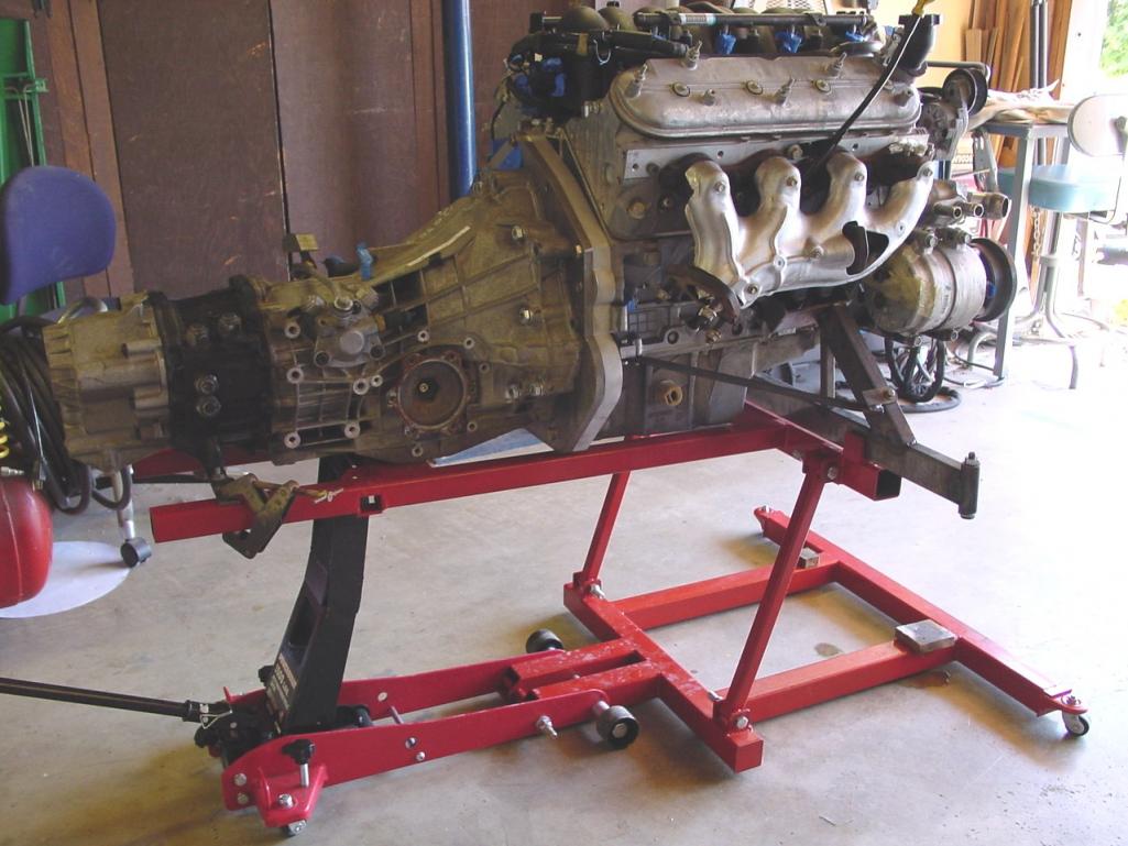 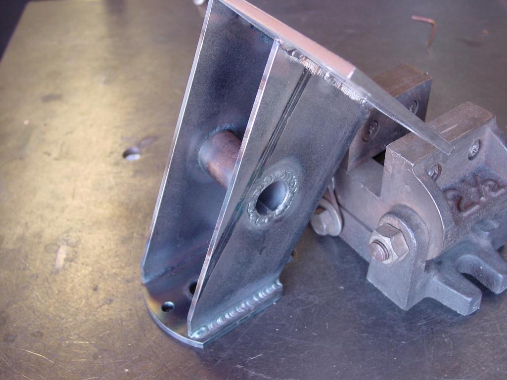 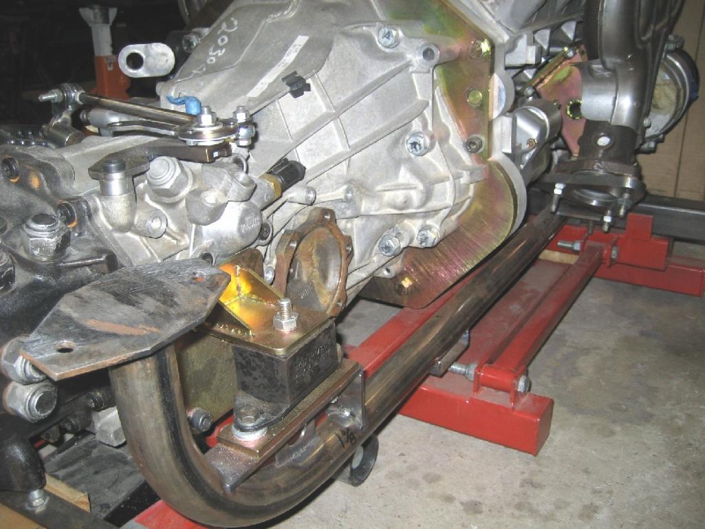 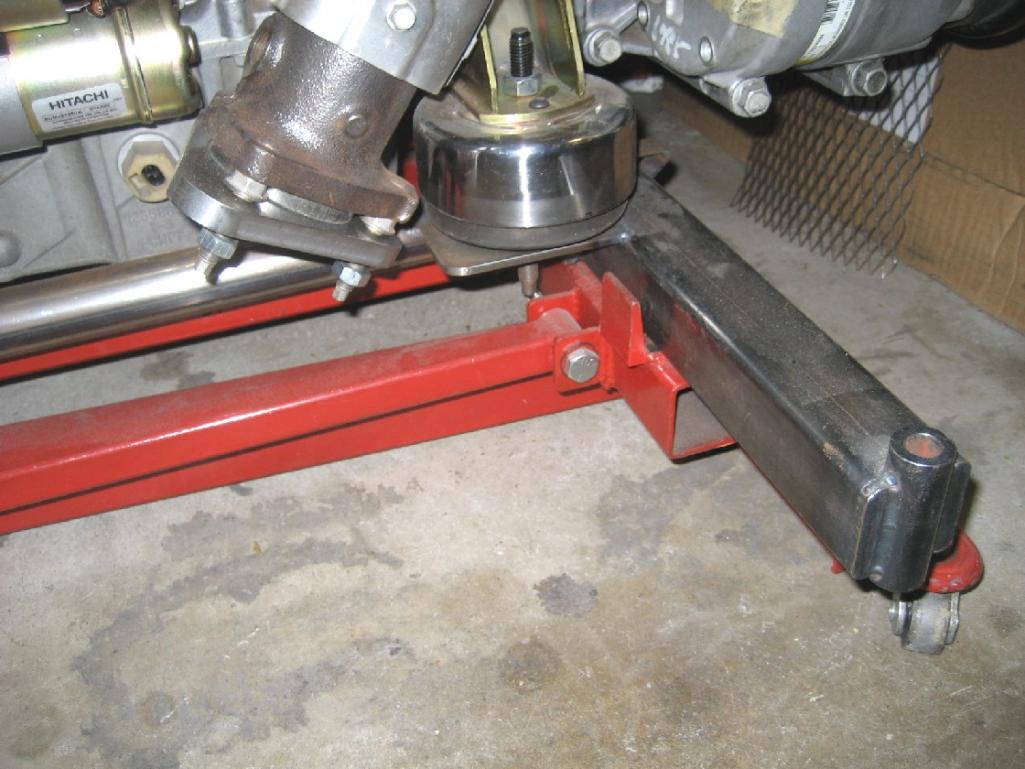 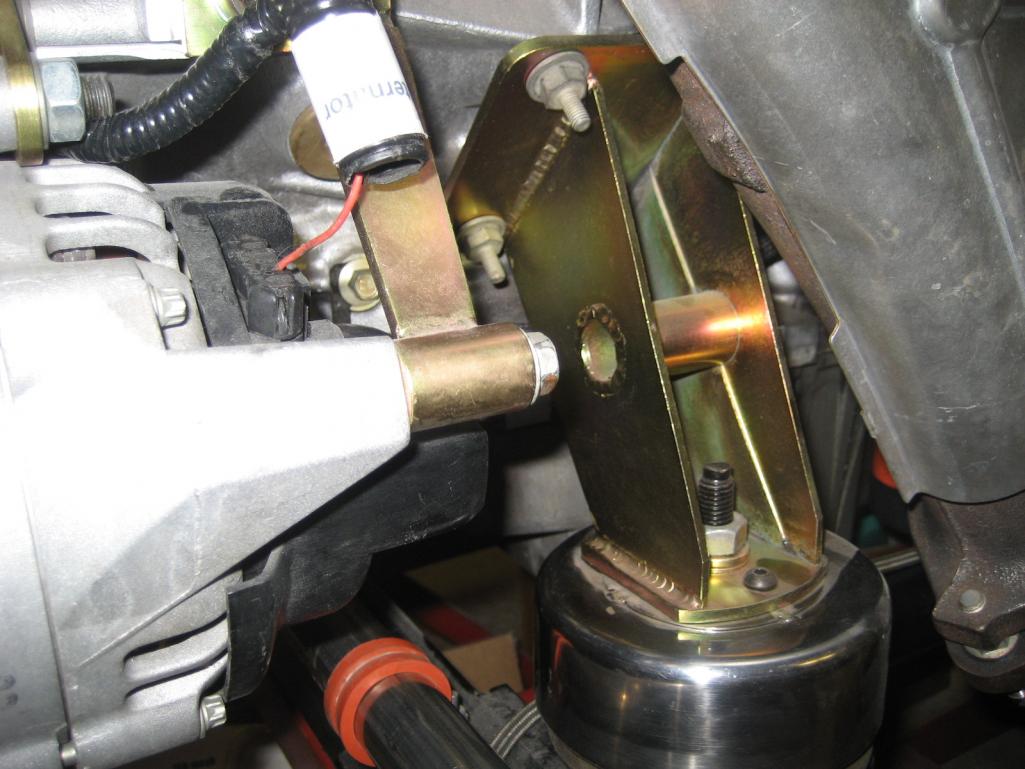 Attached image(s) 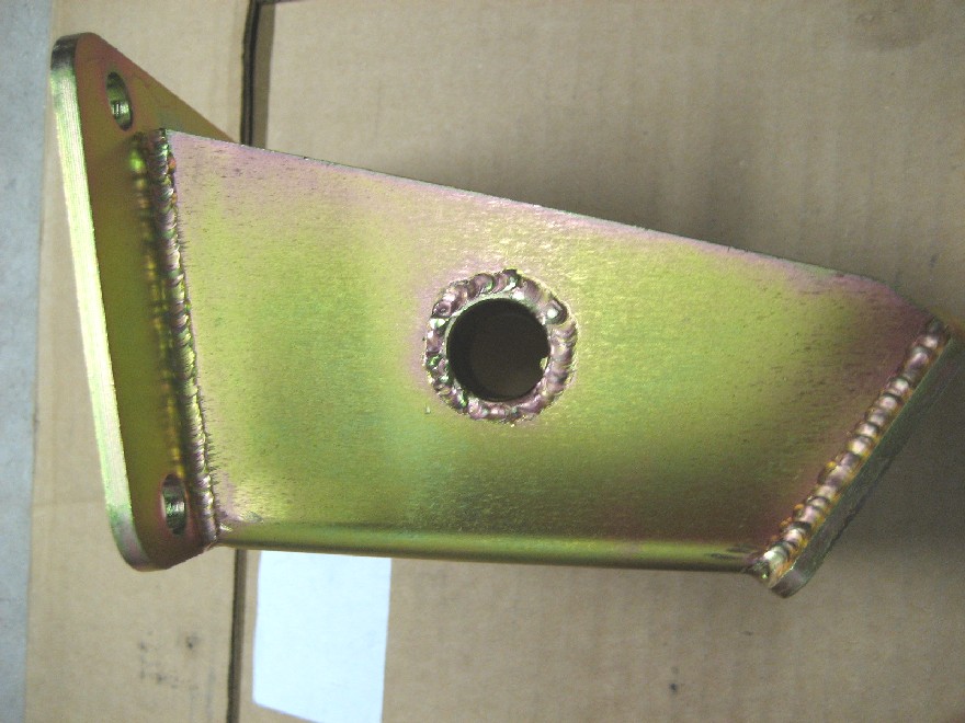 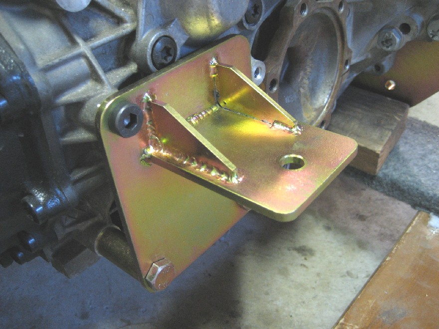
|
| Krieger |
 Feb 24 2013, 07:16 PM Feb 24 2013, 07:16 PM
Post
#28
|
|
Advanced Member     Group: Members Posts: 4,800 Joined: 24-May 04 From: Santa Rosa CA Member No.: 2,104 Region Association: None 
|
I like your work! Weight wise you better off with that mass forward. This car will scoot when your done.
|
| andys |
 Feb 26 2013, 03:30 PM Feb 26 2013, 03:30 PM
Post
#29
|
|
Advanced Member     Group: Members Posts: 2,165 Joined: 21-May 03 From: Valencia, CA Member No.: 721 Region Association: None 
|
The 01E transaxle flanges are a tripoid design which requires adapters to couple to the 911 axles/CV's I intended to use. However, Audi does make an output flange that is the same pattern as the 911 CV; not sure what car/application uses those, but they are available. So why didn't I simply use those instead? Well, it's kind of a convoluted path I took, but perhaps you'll follow my logic(?). Let's see if you can follow this: The 01E output flanges are not symmetrical about the centerline of the transaxle.The centerline offset is 3/4", so one adapter would have to be 1 1/2" thicker than the other. For the axle length to work out properly, the short side adapeter just wouldn't work out (it would if I used the aforementioned compatible output flanges, but there's more). I liked the idea of using the larger 911 wheel bearing, but that won't fit the stock 914 trailing arm......and I wanted to use the 911 rear brakes too, so I decided to make a custom set of trailing arms which would allow me to place the bearing where it wouls accomodate the 911 axle length. More on the trailing arms later.
Anyway, this post is about the transaxle flange adapters and how I resolved that issue. So, to keep axle lengths equal, and hub bearing locations in a favorable location, I decided to offset the motor/transaxle assembly by 3/4" toward the passenger side. So I set about machining adapters that are equal in thickness, and would accept the 911 CV. They would receive a final zinc plating. Andys Attached thumbnail(s) 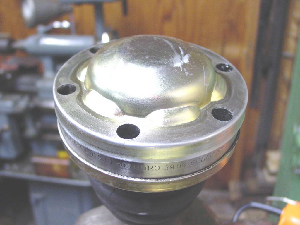 Attached image(s) 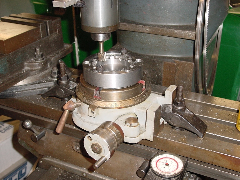 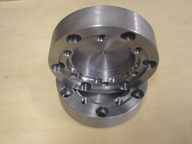 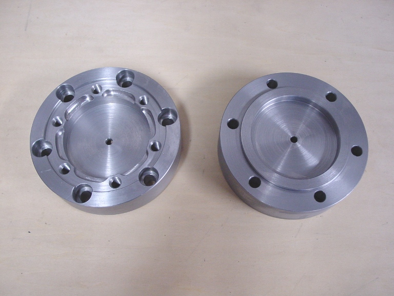
|
| charliew |
 Feb 26 2013, 05:26 PM Feb 26 2013, 05:26 PM
Post
#30
|
|
Advanced Member     Group: Members Posts: 2,363 Joined: 31-July 07 From: Crawford, TX. Member No.: 7,958 |
great work. I also like the jack. I missed the part about the input shaft bearing. Is it the same size as the chevy? Or does the new flywheel have the appropriate bearing?
|
| andys |
 Feb 26 2013, 06:34 PM Feb 26 2013, 06:34 PM
Post
#31
|
|
Advanced Member     Group: Members Posts: 2,165 Joined: 21-May 03 From: Valencia, CA Member No.: 721 Region Association: None 
|
great work. I also like the jack. I missed the part about the input shaft bearing. Is it the same size as the chevy? Or does the new flywheel have the appropriate bearing? I think you're asking about the pilot bearing. I had to machine and adapter that press fit into the Chevy crank, and I press fit an Audi pilot needle bearing into that. The adapter had to move the pilot bearing towards the transaxle in order to engage the input shaft. What I have seen with the designs since then, is where they mount the pilot bearing in an extension that's part of a custom flywheel. Andys |
| andys |
 Feb 27 2013, 06:35 PM Feb 27 2013, 06:35 PM
Post
#32
|
|
Advanced Member     Group: Members Posts: 2,165 Joined: 21-May 03 From: Valencia, CA Member No.: 721 Region Association: None 
|
So we've got the motor/transaxle mounted, and the CV adapters made, how about we move on to making some custom trailing arms. The idea here, is to accomodate the larger 911 hub bearing (and 911 5 lug hub), and since the 911 axles combined with the 01E transaxle place the hub bearing farther outboard by 1.1", I can configure the trailing arm accoringly.
I first started by designing and fabricating a fixture that places everything at the proper relationships to each other. The fixture can make trailing arm geometry with zero, 1 1/2 and 3 degrees of camber relative to the pivot shaft. The stock angle in 1 1/2 degrees. Additionally, I can change the height of the (lower) shock mount to accomodate a lowered car. I chose to stay with the 1 1/2 degrees of camber, and the stock shock mount position (though in retrospect, I should have chosen a lower position). Oh, one other variable the fixture can accomodate, is the bearing carrier position. It can move inboard or outboard....as mentioned, I needed to move it outboard by 1.1" for my setup. First on the list, was to machine the bearing carrier. That was a lot of work mostly due to all the hogging of steel when starting with a solid piece of round bar, but it got done! Then on to machining the other various components including the 911 caliper mount, the handbrake caliper mount, and so on. The pivot shaft housing (tube) is designed to accept Delrin bushings. Once all the pieces were fabricated and placed in the fixture, I started TIG welding. Dang, that was a lot of work! Hopefully, the photos will go a long way towards explaining haow it all got done, cause I don't type so fast! Attached image(s) 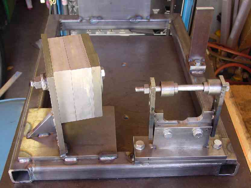 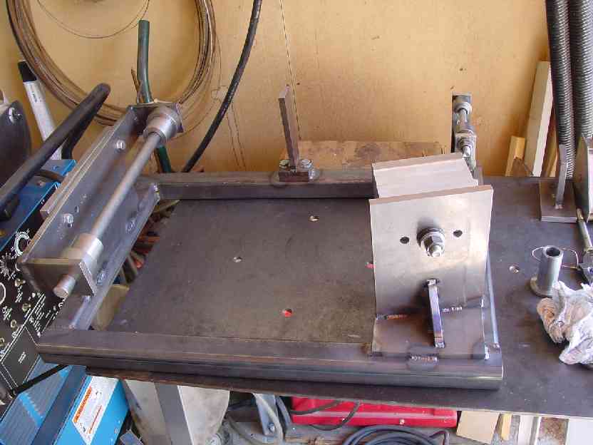 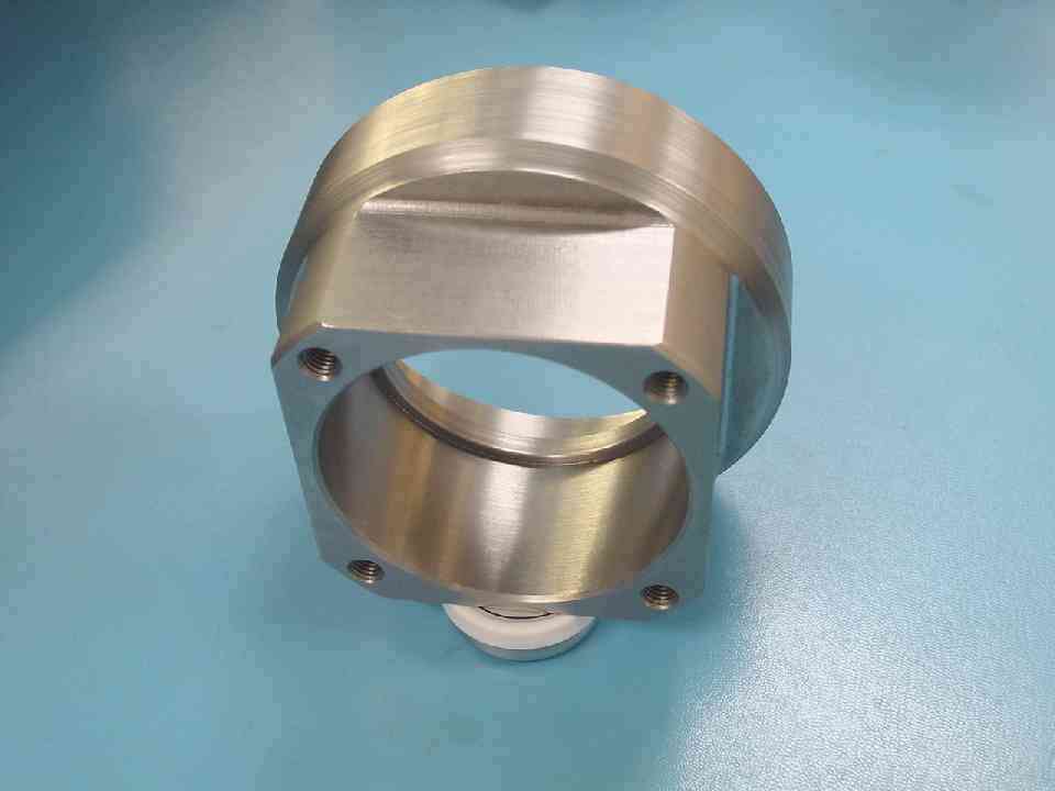 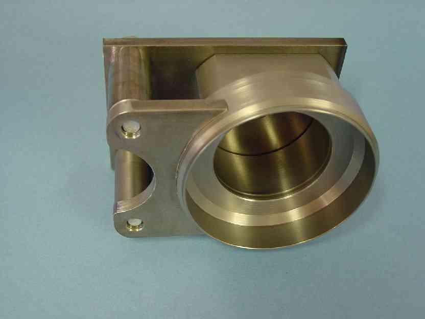 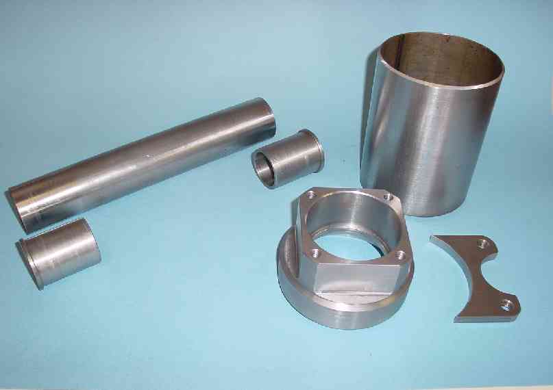 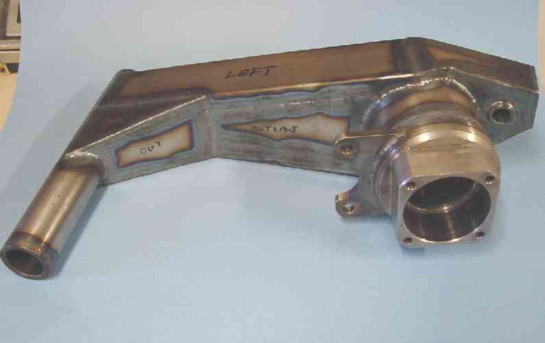 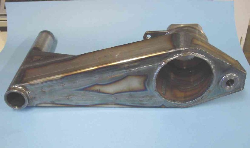 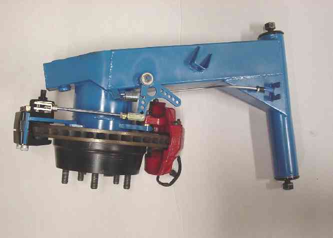
|
| slothness |
 Feb 27 2013, 06:40 PM Feb 27 2013, 06:40 PM
Post
#33
|
|
It's business time   Group: Members Posts: 110 Joined: 7-October 04 From: Valencia, CA Member No.: 2,906 Region Association: Southern California |
|
| trojanhorsepower |
 Feb 27 2013, 06:45 PM Feb 27 2013, 06:45 PM
Post
#34
|
|
Senior Member    Group: Members Posts: 867 Joined: 21-September 03 From: Marion, NC Member No.: 1,179 Region Association: None |
wow........ that is impressive
|
| bigkensteele |
 Feb 27 2013, 10:46 PM Feb 27 2013, 10:46 PM
Post
#35
|
|
Major Member     Group: Members Posts: 2,199 Joined: 30-August 04 From: Cincinnati, OH Member No.: 2,660 Region Association: South East States 
|
You, my friend, are insane! Incredible work!
|
| Bruce Hinds |
 Feb 27 2013, 11:08 PM Feb 27 2013, 11:08 PM
Post
#36
|
|
V-8 madness    Group: Members Posts: 748 Joined: 27-December 06 From: Port Orchard, WA Member No.: 7,391 Region Association: Pacific Northwest |
Holy mother of God! I thought the Jack was a piece of artwork.
|
| andys |
 Feb 28 2013, 12:04 PM Feb 28 2013, 12:04 PM
Post
#37
|
|
Advanced Member     Group: Members Posts: 2,165 Joined: 21-May 03 From: Valencia, CA Member No.: 721 Region Association: None 
|
Thanks for all the nice words!
A couple more comments on the trailing arms. Welded structures are subject to movement due mostly to shrinkage from heat. As such, I did get some movement here and there, but the most significant area was the pivot shaft tube. Basically it was no longer straight, so I had to subsequently heat and bend it until it was straight. Also, the bearing bore diameter, to my surprise, shrunk a small amount which I didn't expect since the weld was what I thought was an adequate distance. Now we're talking about tenth's of a thousanth of an inch, but this is a press fit and needs to stay within a suitable range. In the end, the correct final step after welding, would have been to normalize or stress relieve the structure, but that would have added cost, time, and required an alignment fixture....too much added hassle so I didn't do it. The overall weight of this custom piece is about the same as a stock trailing arm with reinforcement kit, so I think that worked out well. I had considered, and even started machining parts to make an aluminum trailing arm, but the risk just wasn't worth it.......A welded aluminum structure requires a multi step treatment cycle to relieve stresses, normalize, anneal, and heat treat. And in the end, it's still suseptable to sudden fatigue failure. I added a photo of the aluminum bearing carriers that I didn't use. The parking brake is a Wilwood mechanical spot caliper, and I configured the linkage such that the stock 914 parking brake cable and clevis setup could be used without modification. The Wilwood caliper is a floating type which means it sits loosely in it's mount. The result is that it rattles when driving the car; very annoying! What I may do, is design some type of slide cofiguration (pins and bushings) to eliminate the rattle. So the big unanswered question surely on everyone's mind, is why blue? Had a can of Ford engine enamel.......and now that they're on the car, the color looks kinda cool actually. I threw in a photo of the stock trailing arm in the weld fixture. Attached thumbnail(s) 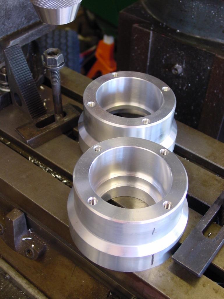 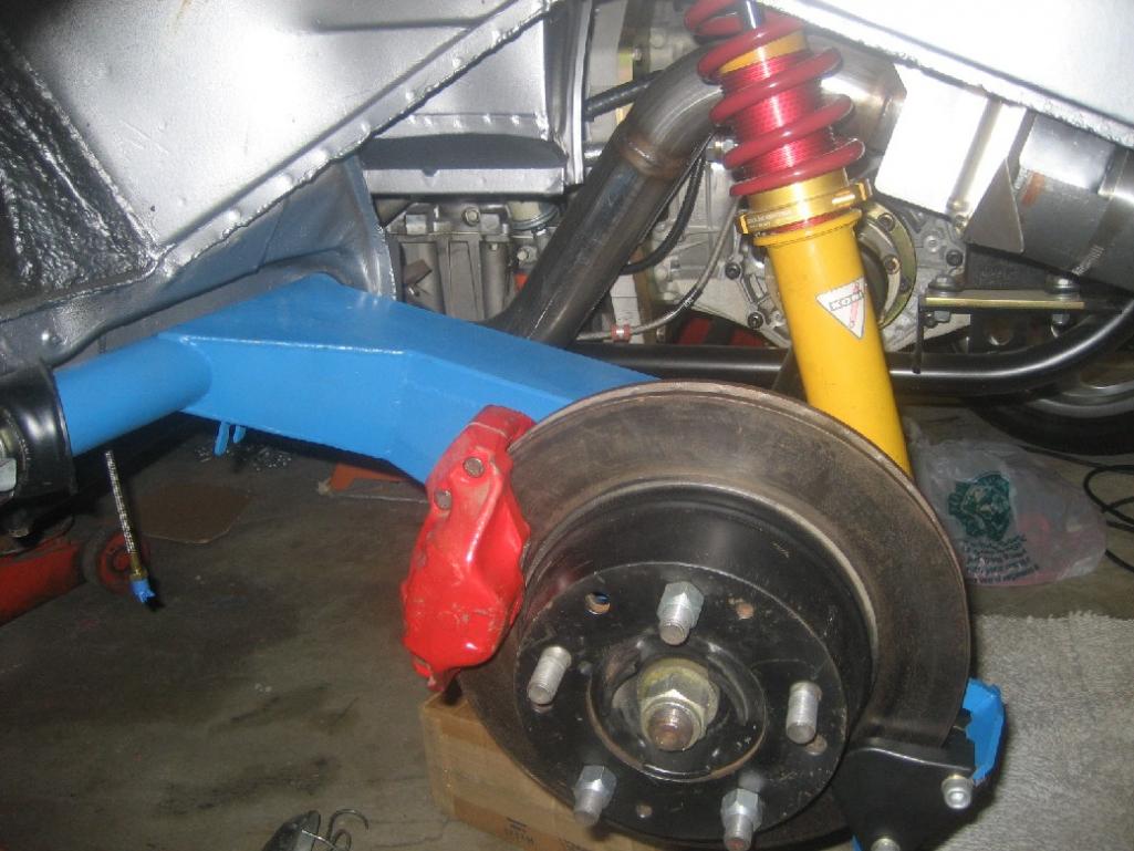 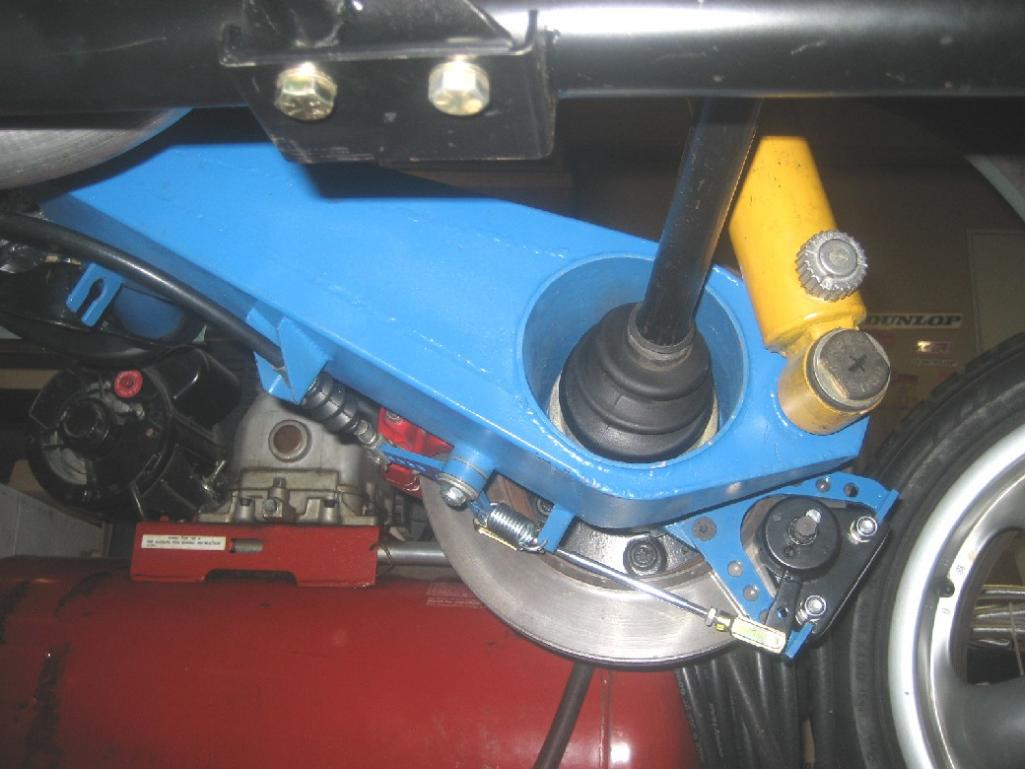 Attached image(s) 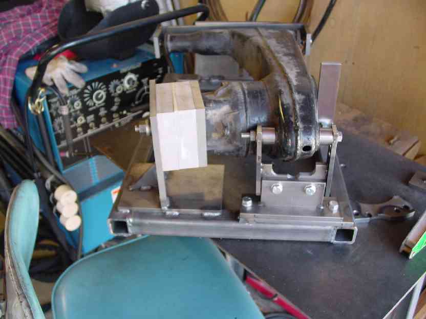 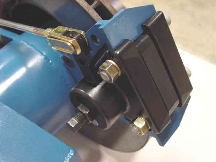
|
| get off my lawn |
 Feb 28 2013, 04:34 PM Feb 28 2013, 04:34 PM
Post
#38
|
|
Member   Group: Members Posts: 168 Joined: 18-August 11 From: west coast Member No.: 13,462 Region Association: None |
What color is that jack, fire engine red?
j/k BTW, this looks like an ad for viagra. Attached image(s) 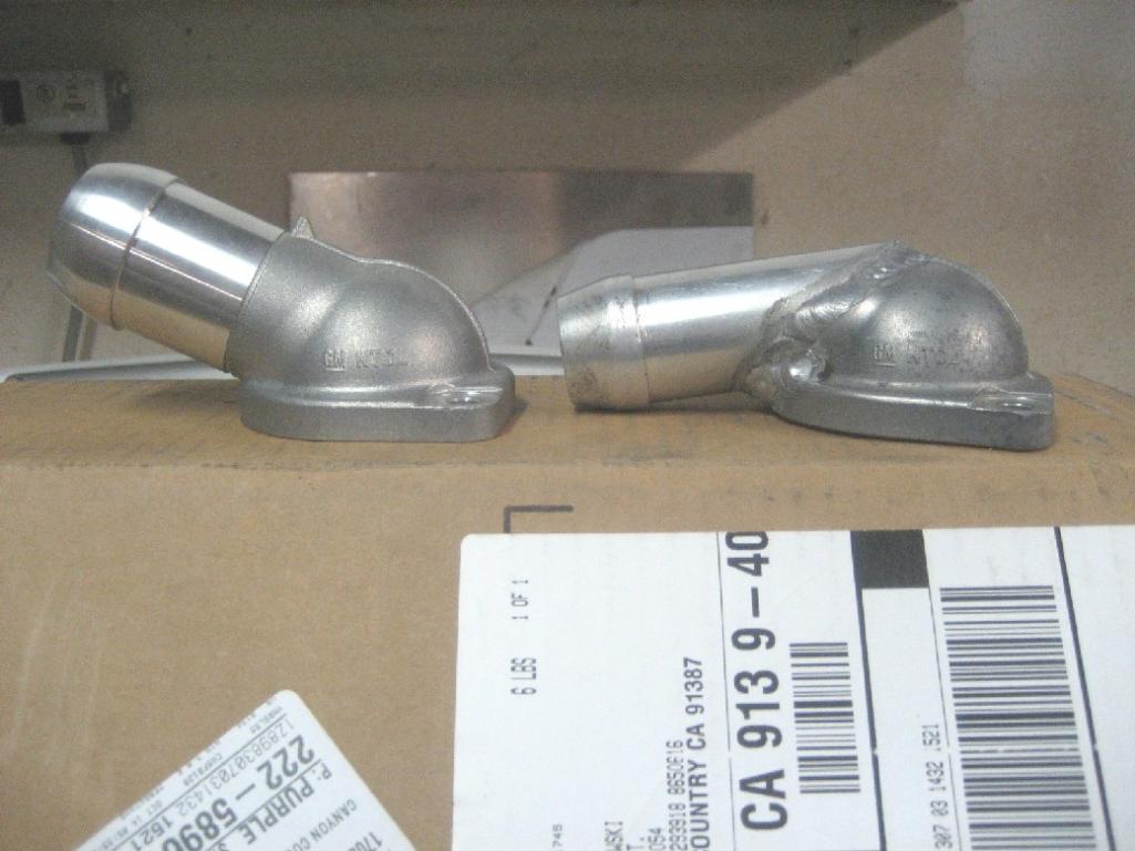
|
| andys |
 Mar 4 2013, 02:33 PM Mar 4 2013, 02:33 PM
Post
#39
|
|
Advanced Member     Group: Members Posts: 2,165 Joined: 21-May 03 From: Valencia, CA Member No.: 721 Region Association: None 
|
I re-enforced the inner suspension ears with a sort of scab plate and boxed combo along with the traditional link to the firewall. I made cardboard templates for the scab plates, cut out some sheet metal, and TIG welded those into place. As with most inner ears, the hole for the pivot shaft usually gets worn out-of-round, so I made sure to add some weld bead and ream the holes true.
I added some double shear pickup points to mount some removable re-enforcement links. What I decided on, was to make a compound link that has two legs; one goes straight forward to the firewall, and the other angles upward and anchors to just above the motor mount structure. Some heims and threaeded clevis', and it's done......oh, and zinc plated. I don't have any real clear shots of the final installation, but I threw in a few where hopefully you casn pick out the re-enforcement scheme. Attached thumbnail(s) 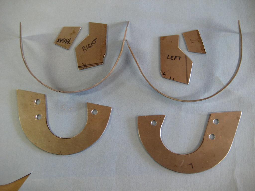 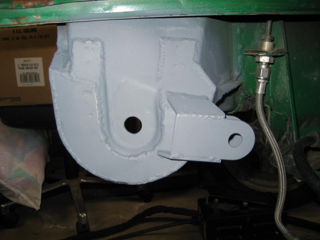 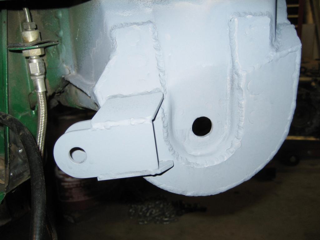 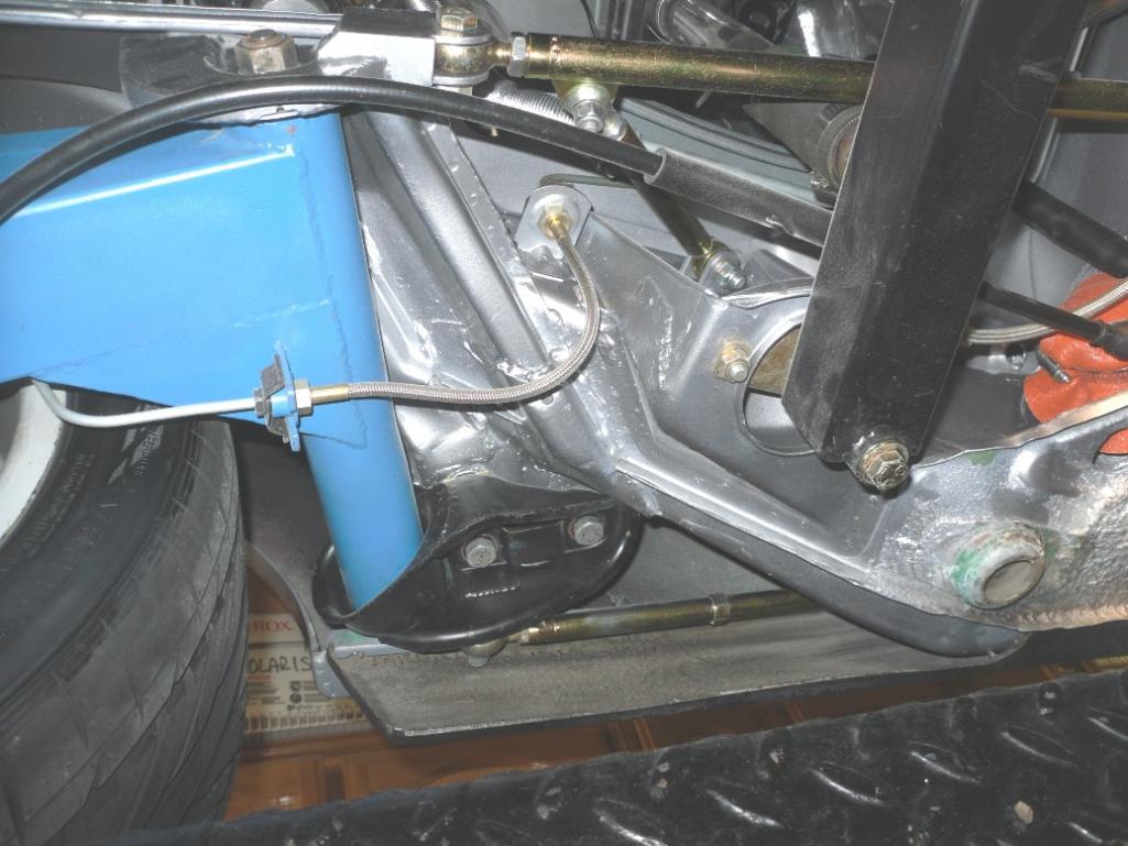 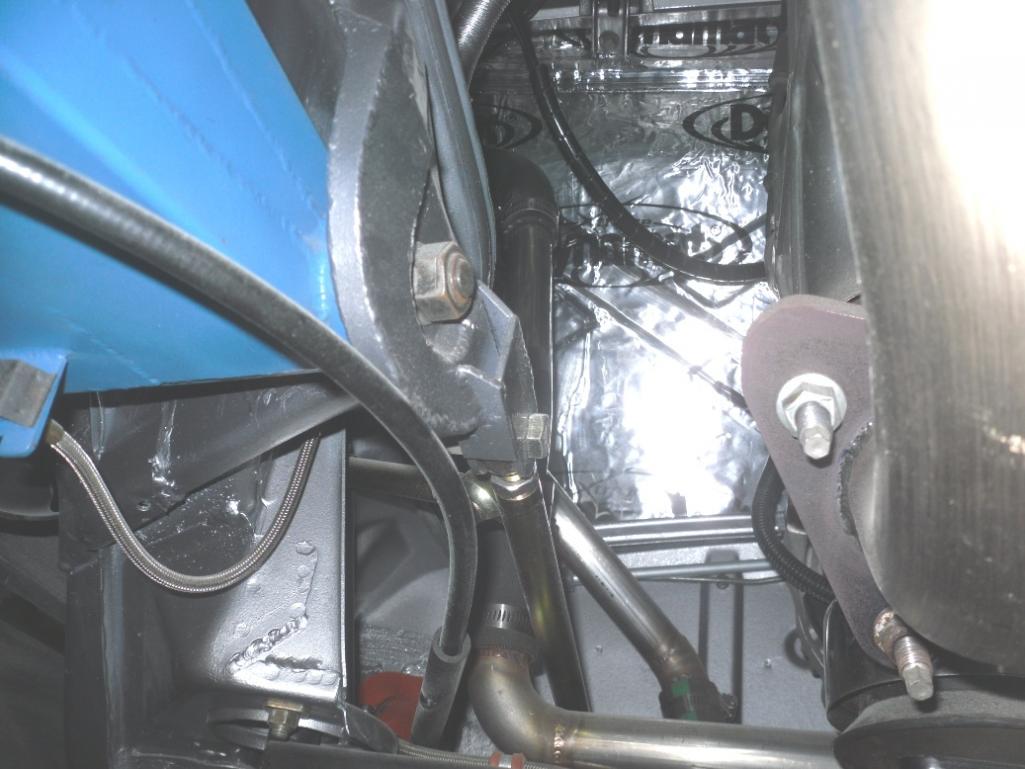 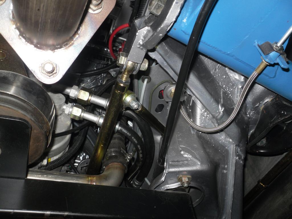 Attached image(s) 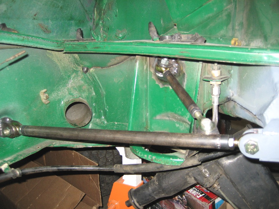 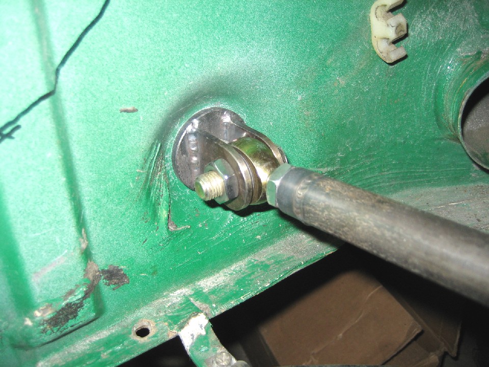
|
| JRust |
 Mar 4 2013, 02:41 PM Mar 4 2013, 02:41 PM
Post
#40
|
|
914 Guru      Group: Members Posts: 6,316 Joined: 10-January 03 From: Albany Oregon Member No.: 129 Region Association: Pacific Northwest 
|
You really should have just made 2 of everything (IMG:style_emoticons/default/smile.gif)
Then sold your leftovers to me cheap (IMG:style_emoticons/default/evilgrin.gif) . Your way ahead of me on your conversion. Not to mention your attention to detail is way beyond mine (IMG:style_emoticons/default/dry.gif) |
  |
2 User(s) are reading this topic (2 Guests and 0 Anonymous Users)
0 Members:

|
Lo-Fi Version | Time is now: 20th April 2025 - 01:58 PM |
Invision Power Board
v9.1.4 © 2025 IPS, Inc.


