|
|

|
Porsche, and the Porsche crest are registered trademarks of Dr. Ing. h.c. F. Porsche AG.
This site is not affiliated with Porsche in any way. Its only purpose is to provide an online forum for car enthusiasts. All other trademarks are property of their respective owners. |
|
|
  |
| Chris H. |
 Jun 8 2014, 07:29 PM Jun 8 2014, 07:29 PM
Post
#261
|
|
Senior Member     Group: Members Posts: 4,048 Joined: 2-January 03 From: Chicago 'burbs Member No.: 73 Region Association: Upper MidWest 
|
Finally finished my hydraulic clutch setup! Whew! Nerve wracking. Normally I don't do much measuring and re-measuring but this time there could not be a mm of extra space. My car is rust free and any car enthusiast from the Midwest knows that you better be REALLY careful cutting holes in or near the floor of an un-galvanized VW product. I think the extra time was worth it, because it's gonna be well sealed.
If you have a 19mm MC and are going to use a bracket like this you might as well drill out the original MC pedal cluster bolts because they will be too short. Be careful not to mangle the surrounding area. It takes a lot of abuse getting kicked with your feet so the metal can't be weak. I used a dremel with a cutoff wheel and then the sand stone grinder. 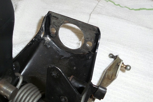 Just need to re-paint it now. Found these 30mm long metric bolts at HD with the lock washer heads. very nice because they grip the cluster so you don't have to clamp them to tighten them. The nut is 13mm just like stock 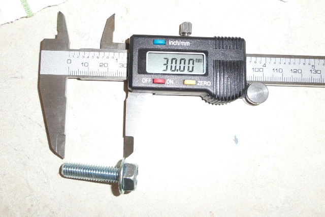 Here's the wide shot. I had to trim mine because the MC had a groove in it. It's a little loose so it looks like it's sagging left (it is). The hole next to it is for the hydraulic line. Used a 5/16 bit and then widened it a little more. 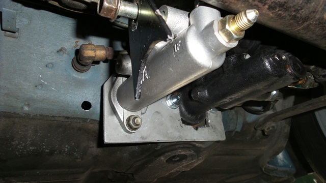 And the side shot. You can see how I measured out for the hole. Just bolted up the bracket without the MC on it and traced out the outline for reference. DO NOT cut the entire hole out. Then I drilled a hole just below the center line starting with small bits and going larger until the hole was large enough to test fit the setup. Need to trim just above the pin as you can see, but the hole is still very small. NOTE: the rubber baffle seal is not installed yet which will seal it up nicely. 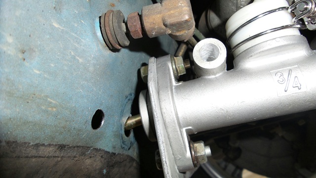 Inside shot. Man the clutch action feels soooooo smooth. I know it will firm up when pressurized but it feels a lot different (better). 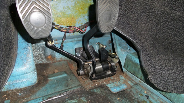 Floor shot 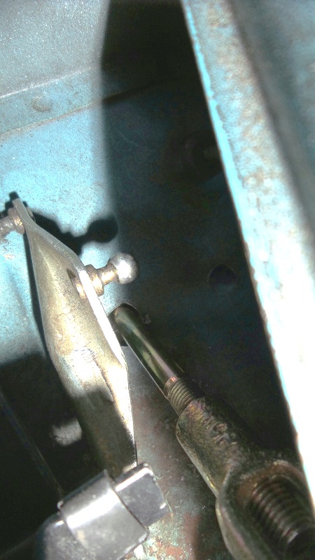 Gotta say very nice engineering Kent! Even though my brake MC required me to trim the bracket, it's still just as strong as before. Once I hook up the brace it'll be awesome. (IMG:style_emoticons/default/beerchug.gif) Next on the list: I cut 2 more holes in the ^&*&^ing trunk for the radiator hoses (small ones) and attach the hoses underneath. |
| Chris914n6 |
 Jun 8 2014, 09:15 PM Jun 8 2014, 09:15 PM
Post
#262
|
|
Jackstands are my life.     Group: Members Posts: 3,413 Joined: 14-March 03 From: Las Vegas, NV Member No.: 431 Region Association: Southwest Region |
Find a local steel supply place. A 4x8 of .050 aluminum is near $50. .050 is what RH uses.
|
| CptTripps |
 Jun 9 2014, 06:24 AM Jun 9 2014, 06:24 AM
Post
#263
|
|
:: Punch and Pie ::     Group: Members Posts: 3,584 Joined: 26-December 04 From: Mentor, OH Member No.: 3,342 Region Association: Upper MidWest |
It's a VERY tight fit in there for sure.
One thing I did differently was to double-brace on either side of the clutch master. I was getting a little movement there and the additional brace seemed to work well. You're also going to want to make the hole through that wall a little bigger. I found that there is a little up/down movement when pushing the clutch in/out. Just a thought or two... Attached image(s) 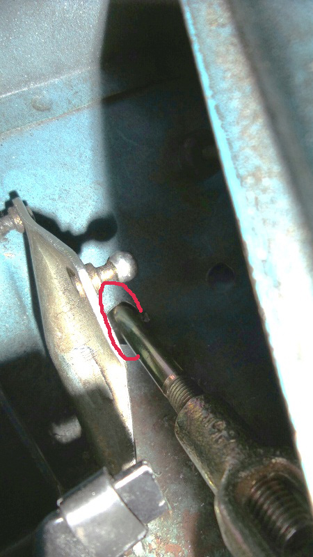 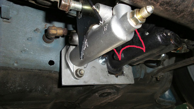
|
| Chris H. |
 Jun 9 2014, 07:41 AM Jun 9 2014, 07:41 AM
Post
#264
|
|
Senior Member     Group: Members Posts: 4,048 Joined: 2-January 03 From: Chicago 'burbs Member No.: 73 Region Association: Upper MidWest 
|
Good call on the extra brace Doug. I enlarged the hole a bit last night after the test fit, just wanted to remove as little as possible. It's probably about 3-4mm larger above the pin. Should be enough but we'll see.
|
| CptTripps |
 Jun 9 2014, 07:45 AM Jun 9 2014, 07:45 AM
Post
#265
|
|
:: Punch and Pie ::     Group: Members Posts: 3,584 Joined: 26-December 04 From: Mentor, OH Member No.: 3,342 Region Association: Upper MidWest |
You should be fine with that. I just bigger than I thought I would need....because I usually under-estimate things.
|
| 76-914 |
 Jun 9 2014, 08:05 AM Jun 9 2014, 08:05 AM
Post
#266
|
|
Repeat Offender & Resident Subaru Antagonist           Group: Members Posts: 13,634 Joined: 23-January 09 From: Temecula, CA Member No.: 9,964 Region Association: Southern California 
|
(IMG:style_emoticons/default/thumb3d.gif) Great job, Chris. Doug is correct. There is about 3/8" up n down movement on that rod due to the movement of the pedal cam thru it's cycle. I ended up with a 3/4" hole which I thought was small but I don't live in lower Slobovia, either. (IMG:style_emoticons/default/lol-2.gif) That bellows seal will cover any hole up to 1.5". Once you've determined the clutch pedal travel, set the stop nut on the end of the pedal. I suspect this is where Doug "felt" flexing or his floor metal is thin. You shouldn't have to exert more than 5lb pressure to engage the clutch so if the pedal flexes and adding one brace 2" to the right side helps, I'd look elsewhere. IOW, if it flexes, the left side of the cluster is receiving the down force and the right side the up force, so a brace on the right should be unnecessary but it won't hurt anything either. Good to see you posting again, Chris. Hurry, you only have 3 weeks until Winter strikes Chicagoland again. (IMG:style_emoticons/default/lol-2.gif)
|
| Chris H. |
 Jun 9 2014, 09:17 PM Jun 9 2014, 09:17 PM
Post
#267
|
|
Senior Member     Group: Members Posts: 4,048 Joined: 2-January 03 From: Chicago 'burbs Member No.: 73 Region Association: Upper MidWest 
|
Well, I finally headed back to the engine bay to work on the exhaust/engine mount stuff and noticed this:
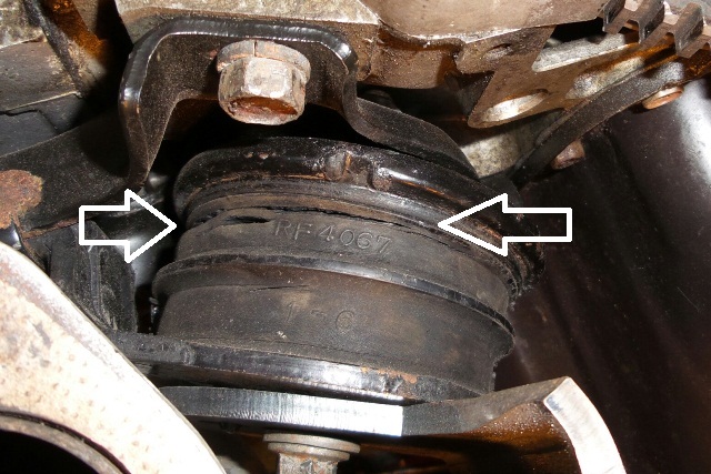 Left Subie motor mount.... I knew it was cracked before but over the winter it really opened up. Probably can't ignore it any more or it will crack in half. It's 20 years old...can't be too surprised. Looks like the SVX guys do one of three things: 1. replace these with STI "Group N" mounts ($150 shipped per pair) 2. Fill the cracked mounts with urethane and let them harden (sounds sketchy) 3. buy new ones for ~$300+ (nope) I noticed the PrecisionChassis 3.3L looks like the engine cradle is bolted directly to the engine at the motor mount points without any rubber isolators. Always wondered if I could do something like that since I have rubber mounts at both ends of my cradle. |
| mgp4591 |
 Jun 10 2014, 05:23 AM Jun 10 2014, 05:23 AM
Post
#268
|
|
914 Guru      Group: Members Posts: 5,482 Joined: 1-August 12 From: Salt Lake City Ut Member No.: 14,748 Region Association: Intermountain Region 
|
Well, I finally headed back to the engine bay to work on the exhaust/engine mount stuff and noticed this:  Left Subie motor mount.... I knew it was cracked before but over the winter it really opened up. Probably can't ignore it any more or it will crack in half. It's 20 years old...can't be too surprised. Looks like the SVX guys do one of three things: 1. replace these with STI "Group N" mounts ($150 shipped per pair) 2. Fill the cracked mounts with urethane and let them harden (sounds sketchy) 3. buy new ones for ~$300+ (nope) I noticed the PrecisionChassis 3.3L looks like the engine cradle is bolted directly to the engine at the motor mount points without any rubber isolators. Always wondered if I could do something like that since I have rubber mounts at both ends of my cradle. I wouldn't want to trust that for a couple of reasons. First, I think the engine vibration could promote cracking at weld points on the cradle or possibly more. The 3.3 has a good amount of torque- might pretzel up a cradle. Second, vibration into the rest of the car could make a harmonic howl that drives you crazy! (IMG:style_emoticons/default/blink.gif) |
| Chris H. |
 Jun 10 2014, 07:00 AM Jun 10 2014, 07:00 AM
Post
#269
|
|
Senior Member     Group: Members Posts: 4,048 Joined: 2-January 03 From: Chicago 'burbs Member No.: 73 Region Association: Upper MidWest 
|
Yeah the vibration is what I'm worried about. Looks like the Group Ns are pretty stiff. Another project! Yeah! (IMG:style_emoticons/default/smilie_pokal.gif)
|
| BIGKAT_83 |
 Jun 10 2014, 07:15 AM Jun 10 2014, 07:15 AM
Post
#270
|
|
Senior Member    Group: Members Posts: 1,798 Joined: 25-January 03 From: Way down south Bogart,GA Member No.: 194 Region Association: South East States 

|
Found the right side mount,still looking for the left. PM me your address and I'll ship you a set.
Bob |
| Chris H. |
 Jun 10 2014, 07:22 AM Jun 10 2014, 07:22 AM
Post
#271
|
|
Senior Member     Group: Members Posts: 4,048 Joined: 2-January 03 From: Chicago 'burbs Member No.: 73 Region Association: Upper MidWest 
|
Thanks Bob! Will do! That saves me a huge pile of money and time!
|
| 76-914 |
 Jun 10 2014, 02:40 PM Jun 10 2014, 02:40 PM
Post
#272
|
|
Repeat Offender & Resident Subaru Antagonist           Group: Members Posts: 13,634 Joined: 23-January 09 From: Temecula, CA Member No.: 9,964 Region Association: Southern California 
|
FYI, I just noticed that the pic Doug posted has the brace on the wrong side. That might induce some flex. Also, I recommend that you take a piece of 2" PVC x 1.5" long and when looking at it from the end, cut out a section from 12 o'clock to 4 o'clock. This piece will "snap" over the steering rack. Once on, rotate it until the void (12-4) is facing down. This will give the clearance needed for the steering cover to bolt up w/o interference. There will be enough room for this piece to fit between obstacles but only on the left side. The reason for this PVC piece is twofold. 1st is to protect the metal on the steering arm from the harder steel brace and secondly it should have some quietening effect upon the pedal assm.
|
| Chris H. |
 Jun 10 2014, 03:49 PM Jun 10 2014, 03:49 PM
Post
#273
|
|
Senior Member     Group: Members Posts: 4,048 Joined: 2-January 03 From: Chicago 'burbs Member No.: 73 Region Association: Upper MidWest 
|
FYI, I just noticed that the pic Doug posted has the brace on the wrong side. That might induce some flex. Also, I recommend that you take a piece of 2" PVC x 1.5" long and when looking at it from the end, cut out a section from 12 o'clock to 4 o'clock. This piece will "snap" over the steering rack. Once on, rotate it until the void (12-4) is facing down. This will give the clearance needed for the steering cover to bolt up w/o interference. There will be enough room for this piece to fit between obstacles but only on the left side. The reason for this PVC piece is twofold. 1st is to protect the metal on the steering arm from the harder steel brace and secondly it should have some quietening effect upon the pedal assm. My brace is on the correct side then? I think it is. Great call on the PVC. I was planning to use some extra rubber welting or something. |
| 76-914 |
 Jun 11 2014, 12:47 PM Jun 11 2014, 12:47 PM
Post
#274
|
|
Repeat Offender & Resident Subaru Antagonist           Group: Members Posts: 13,634 Joined: 23-January 09 From: Temecula, CA Member No.: 9,964 Region Association: Southern California 
|
FYI, I just noticed that the pic Doug posted has the brace on the wrong side. That might induce some flex. Also, I recommend that you take a piece of 2" PVC x 1.5" long and when looking at it from the end, cut out a section from 12 o'clock to 4 o'clock. This piece will "snap" over the steering rack. Once on, rotate it until the void (12-4) is facing down. This will give the clearance needed for the steering cover to bolt up w/o interference. There will be enough room for this piece to fit between obstacles but only on the left side. The reason for this PVC piece is twofold. 1st is to protect the metal on the steering arm from the harder steel brace and secondly it should have some quietening effect upon the pedal assm. My brace is on the correct side then? I think it is. Great call on the PVC. I was planning to use some extra rubber welting or something. The brace goes between the two M/C's, the left side of the clutch MC. (IMG:style_emoticons/default/beerchug.gif) |
| CptTripps |
 Jun 11 2014, 01:13 PM Jun 11 2014, 01:13 PM
Post
#275
|
|
:: Punch and Pie ::     Group: Members Posts: 3,584 Joined: 26-December 04 From: Mentor, OH Member No.: 3,342 Region Association: Upper MidWest |
I forget what I switched it to, but one side gave me a ton of flex, and the other was solid. I did have it wrong at one point. I ended up adding a second just to be safe. Now it's solid as a rock.
|
| Chris H. |
 Jun 11 2014, 02:40 PM Jun 11 2014, 02:40 PM
Post
#276
|
|
Senior Member     Group: Members Posts: 4,048 Joined: 2-January 03 From: Chicago 'burbs Member No.: 73 Region Association: Upper MidWest 
|
So I had it on wrong too then...is what you're saying very nicely Kent... (IMG:style_emoticons/default/lol-2.gif)
See that's why I'm going slow...been a little stressed lately...I'm surprised you didn't notice this... 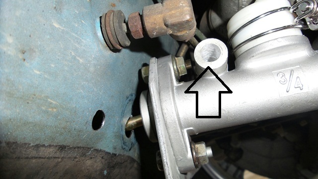 Yeah I drilled out and widened THE WRONG HOLE for the brace initially. No harm done but I felt pretty stupid. That's when I stopped for a week or so and gathered more parts. Back at it now though! |
| Chris H. |
 Jun 17 2014, 01:45 PM Jun 17 2014, 01:45 PM
Post
#277
|
|
Senior Member     Group: Members Posts: 4,048 Joined: 2-January 03 From: Chicago 'burbs Member No.: 73 Region Association: Upper MidWest 
|
Wellll....really good day today!
Got my speedhut gauges: 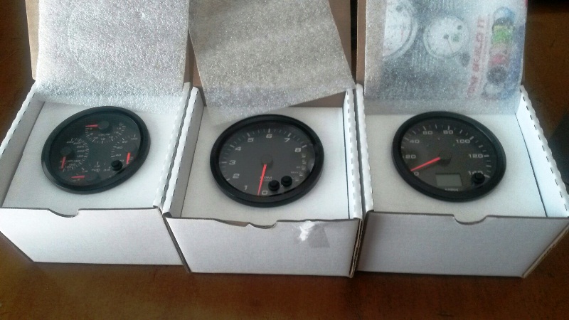 And even better, I got this from BIGKAT_83. 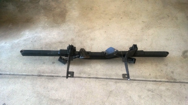 I bought my exhaust setup from Bob last year and knew it might take some fiddling to get it to fit with Ian's cradle but I wanted it. Then I recently found a cracked motor mount (has nothing to do with the cradle or exhaust, it's just 20 years old). So Bob GAVE ME his old mount which bolts directly to the engine. It's similar to the smallcar mount and very sturdy and strong. Can't wait to get it bolted up! Everything will fit perfectly now. Thanks again Bob!!!! (IMG:style_emoticons/default/beerchug.gif) |
| Chris H. |
 Jun 17 2014, 03:18 PM Jun 17 2014, 03:18 PM
Post
#278
|
|
Senior Member     Group: Members Posts: 4,048 Joined: 2-January 03 From: Chicago 'burbs Member No.: 73 Region Association: Upper MidWest 
|
Keeps getting better.... Got a package from Kent! Some pedal cluster stuff and half a map cylinder to attach to the front valance. Just in time too! My pictures were not legible enough to post but I'll take some more later. Thanks Kent!
|
| 76-914 |
 Jun 17 2014, 05:11 PM Jun 17 2014, 05:11 PM
Post
#279
|
|
Repeat Offender & Resident Subaru Antagonist           Group: Members Posts: 13,634 Joined: 23-January 09 From: Temecula, CA Member No.: 9,964 Region Association: Southern California 
|
Wellll....really good day today! Got my speedhut gauges:  And even better, I got this from BIGKAT_83.  I bought my exhaust setup from Bob last year and knew it might take some fiddling to get it to fit with Ian's cradle but I wanted it. Then I recently found a cracked motor mount (has nothing to do with the cradle or exhaust, it's just 20 years old). So Bob GAVE ME his old mount which bolts directly to the engine. It's similar to the smallcar mount and very sturdy and strong. Can't wait to get it bolted up! Everything will fit perfectly now. Thanks again Bob!!!! (IMG:style_emoticons/default/beerchug.gif) Those are sweet. Hide the bill from your wife. (IMG:style_emoticons/default/lol-2.gif) I'm just jealous. (IMG:style_emoticons/default/hissyfit.gif) Shoot us a pic of your cracked mount. I want to be sure I didn't miss that and a pic would help. FWIW, I shit canned those stamped metal pieces (w/3 bolt holes on the front mounts) and replaced them with 3/16" plate steel. Keep after it my brother. (IMG:style_emoticons/default/poke.gif) You only have 2 more weeks of summer in Chicago. |
| euro911 |
 Jun 17 2014, 10:37 PM Jun 17 2014, 10:37 PM
Post
#280
|
|
Retired & living the dream. God help me if I wake up!      Group: Members Posts: 8,858 Joined: 2-December 06 From: So.Cal. & No.AZ (USA) Member No.: 7,300 Region Association: Southern California 
|
ellll....really good day today! Nice (IMG:style_emoticons/default/smile.gif) ... Did you get them to eliminate the 'Speedhut' printing?Got my speedhut gauges:  ... ... |
  |
1 User(s) are reading this topic (1 Guests and 0 Anonymous Users)
0 Members:

|
Lo-Fi Version | Time is now: 24th November 2024 - 04:39 AM |
Invision Power Board
v9.1.4 © 2024 IPS, Inc.


