|
|

|
Porsche, and the Porsche crest are registered trademarks of Dr. Ing. h.c. F. Porsche AG.
This site is not affiliated with Porsche in any way. Its only purpose is to provide an online forum for car enthusiasts. All other trademarks are property of their respective owners. |
|
|
  |
| spunone |
 Oct 9 2006, 02:45 PM Oct 9 2006, 02:45 PM
Post
#461
|
|
Senior Member    Group: Members Posts: 945 Joined: 6-April 04 From: Anaheim CA Member No.: 1,901 Region Association: Southern California |
Don't know about a hinge thing on bottom of car may get a little to much Grit on it and no workie...Just my .02 (IMG:style_emoticons/default/blink.gif)
|
| Crazyhippy |
 Oct 9 2006, 04:27 PM Oct 9 2006, 04:27 PM
Post
#462
|
|
Insert witty comment here...    Group: Members Posts: 1,659 Joined: 28-July 05 From: Home of the Coyotes, AZ Member No.: 4,493 Region Association: None |
how'd the car do on the drive home???
BJH |
| TonyAKAVW |
 Oct 9 2006, 04:30 PM Oct 9 2006, 04:30 PM
Post
#463
|
|
That's my ride.     Group: Members Posts: 2,151 Joined: 17-January 03 From: Redondo Beach, CA Member No.: 166 Region Association: None |
|
| Crazyhippy |
 Oct 9 2006, 04:40 PM Oct 9 2006, 04:40 PM
Post
#464
|
|
Insert witty comment here...    Group: Members Posts: 1,659 Joined: 28-July 05 From: Home of the Coyotes, AZ Member No.: 4,493 Region Association: None |
me too...
amazing what a little torque will do for you gearing choices BJH |
| Aaron Cox |
 Oct 9 2006, 06:36 PM Oct 9 2006, 06:36 PM
Post
#465
|
|
Professional Lawn Dart                Group: Retired Admin Posts: 24,541 Joined: 1-February 03 From: OC Member No.: 219 Region Association: Southern California |
talk to me about what ratios you want.....
a flipped H will cost ~400 ish i can find em for ya.... |
| fat73 |
 Oct 9 2006, 07:12 PM Oct 9 2006, 07:12 PM
Post
#466
|
|
W9R1   Group: Members Posts: 244 Joined: 7-May 05 From: tampa,fl Member No.: 4,043 Region Association: South East States |
I was at Dave White Autosports in Tampa today getting the corner balance and alignment done, and saw some pictures of a 914 that had scoops cut into the targa sails. Essentially the outside was cut in front, top and bottom, and pushed out, bent down on top and bottom to form the scoop and fabricated in, and on the inside it was cut and pushed out to meet the outside scoop. According to the guy that did it, he felt it even made the top stronger. Anyway, thinking of doing this for some intercooler flow, but so far mycar hasn't been past 190 in Tampa weather in heavy traffic (renegade w/Ron Davis front radiator). Stays around 180 most of the time.
Ed aka W9R1 |
| dmenche914 |
 Oct 13 2006, 03:52 AM Oct 13 2006, 03:52 AM
Post
#467
|
|
Senior Member    Group: Members Posts: 1,212 Joined: 27-February 03 From: California Member No.: 366 |
Any photos of the best so far radiator/scoop arrangements to post?
i want ot redo a V6 radiator system, and would like to retain the front trunk. My thought is two smaller radiator on either side of the motor, set horizontally, with fans to help air flow up and out. Might get a bit warm however in stop and go traffic, with the exhaust pre-heated are being blown ontot he radiator from below, probably less of an issue at speed. any thought on that? The V6 is too long a motor to allow a radiator in front of the motor like the subaru motor. Might try a raised up engine lid grill, to get the radiator higher up, which will aloow a thicker radiator. Any thought on this? By the way, very nice looking project so far! |
| TonyAKAVW |
 Oct 13 2006, 10:36 AM Oct 13 2006, 10:36 AM
Post
#468
|
|
That's my ride.     Group: Members Posts: 2,151 Joined: 17-January 03 From: Redondo Beach, CA Member No.: 166 Region Association: None |
I don't personally know what the cooling requirements are for a V6, though I encourage you to experiment. From experience I can tell you that you will need some kind of pressure-inducing element, either a scoop above or below the car, or sometihng to generatre low pressure on the output side of the radiator.
So however you orient the radiator(s), make sure you have space to duct some air to them. No photos yet of the current cooling setup. Its a complete hack compared to the other stuff I've posted here, so until I get it working really really well, AND have it look halfway decent I'm not going to put up pictures. However if you go back a bunch of pages I have numerous diagrams of how the undercar scoop idea works. The current setup is basically that.. -Tony |
| scotty914 |
 Oct 15 2006, 08:00 PM Oct 15 2006, 08:00 PM
Post
#469
|
|
suby torque rules    Group: Members Posts: 1,528 Joined: 20-July 03 From: maryland, the land of 25 year Member No.: 924 |
well tony, i am glad you got it to cool, even if just marginally for now. it definatly need to fix the speed sensor thing, it get much more fun over 4500 rpm
and i am only doing this because i can ....." i told ya so ".... even thou i dont know if i did, sorry |
| TonyAKAVW |
 Oct 16 2006, 10:59 AM Oct 16 2006, 10:59 AM
Post
#470
|
|
That's my ride.     Group: Members Posts: 2,151 Joined: 17-January 03 From: Redondo Beach, CA Member No.: 166 Region Association: None |
I think I finally fixed my Vehicle Speed sensor. Here's the details of what I did and why I think certain things didn't work.
First off, the Subaru normally uses a magnetic reed switch that is triggered by a rotating magnet in the transmission. This signal is distributed to both the transmission control module and the ECU. In reality it isn't a signal until a voltage is applied to one end of the reed switch. This is important later... So in my attempt to overdo things, I thought it would be nice to eliminate a mechanical part in favor of a modern semiconductor, namely a hall effect sensor. So I bought some hall effect sensors, built a tiny module with lots of overvoltage and ESD protection, etc. It was all nicely potted in silicone and protected by a small glass vial. It even had a green LED on it so for troubleshooting I could see what state it was in. (the sensor was activated by 16 alternating polarity magnets glued to the CV joint) The Hall-effect module worked great except that it didn't work with the ECU. I had a small frequency counter and used it as a speedometer and it was quite accurate, giving about 1 Hz per mph. (this translates to 4 pulses per revolution of the wheel) Something I discovered as I was working on this is tha tthe ECU provides a +5 on the VSS input pin, because it is expecting to see a reed switch. I had been feeding it a 5 volt square wave, which in theory should work, but I suspect the input for the VSS was designed specifically for a reed switch and is particularly sensitive. After all this I decided to give the reed switch a try. I went to Radio Shack and bought a magnetic alarm switch and made a bracket for it. Last night I took the car out for half an hour and basically got onto and off of the freeway a bunch of times to get the engine revved up and down. No problems. Normally the ECU would have tripped the limp-home mode by that point and I would have been stuck with a 4300 rpm redline. Eventually I want to put a hall sensor in, and I believe it will work. The problem is that the kind of hall sensor I used has additional smarts in it that were causing me problems. Namely it is a latching type hall sensor. So when a magnet of one polarity trips it, it goes into one state, until a magnet of the other polarity pulls it back down. This gives you a really nice square wave, but its apparently not what the ECU wants to see. What ought to work however is a non-latching hall sensor. When I replace my reed switch, I will use one of these. Something I'm interested in still though is what goes on at freeway speeds. If my math is right, at 70 mph, the 16 magnets will be passing by the reed switch for 7 micro seconds each. I'm willing to bet that the reed switch doesn't even flinch. The solution to this (thanks Evan) is to make the magnet longer. I will hook up my oscilliscope to the VSS input some evening and watch the display as I'm driving to see how fast I can go before the reed switch stops closing. -Tony |
| mrdezyne |
 Oct 16 2006, 02:25 PM Oct 16 2006, 02:25 PM
Post
#471
|
|
Now on larger rolling jack stands!   Group: Members Posts: 468 Joined: 31-July 05 From: Tulsa, OK Member No.: 4,510 |
Please let us know how this works out. Exerpts of this thread are going into my "SUBIE CONVERSION BIBLE" as I know I will be needing to follow you with the same type of speed sensor. Thanks!
|
| jsteele22 |
 Oct 16 2006, 02:33 PM Oct 16 2006, 02:33 PM
Post
#472
|
|
Senior Member    Group: Members Posts: 727 Joined: 24-August 05 From: Colorado Springs, CO Member No.: 4,653 |
Something I discovered as I was working on this is tha tthe ECU provides a +5 on the VSS input pin, because it is expecting to see a reed switch. I had been feeding it a 5 volt square wave, which in theory should work, but I suspect the input for the VSS was designed specifically for a reed switch and is particularly sensitive. Eventually I want to put a hall sensor in, and I believe it will work. The problem is that the kind of hall sensor I used has additional smarts in it that were causing me problems. Namely it is a latching type hall sensor. So when a magnet of one polarity trips it, it goes into one state, until a magnet of the other polarity pulls it back down. This gives you a really nice square wave, but its apparently not what the ECU wants to see. What ought to work however is a non-latching hall sensor. When I replace my reed switch, I will use one of these. The sensor input of the ECU is a kind that sounds weird, but is fairly common, especially in industrial controls. Internal to the module, the input line has a resistor that connects to +5V. It's called a "pull-up" resistor, b/c when no external signal is applied no current flows through the resistor, so the input is "pulled up" to +5V also. To provide an input, you can touch the input to ground; now, a current flows from +5V thropugh the rsistor to ground and the input, being at the low end of the reistor, is also at ground. That's what the relay accomplishes. To interface with this input, you should look for one whose output is either "open collector" or "pull-up". The latter simply adds a second pullup resistor to the system, so you will have 2 in parallel, but that's okay. But both of them contain a transitor output stage that will either pull the signal low (around 0 V) or let it get pulled high. This is the same behavior as the relay. Actually, you could use the other common kind of output ("push-pull" or "logic" or "totem-pole"), which actually forces the line into a high or low state. The only risk is that if the output is being driven high and for some reason you touch the line to ground, you'll burn out the transitor. I think you're right about not wanting a latched output. It is handy to have what are called "Schmidt Trigger" inputs; these are available on some sensors. This is a clever feature that prevents small noise fluctuations on a slowly rising signal from causing the switch to output tons of spurious on/off transitions as the noise goes above/below the threshold. Probably the ECU has it's own internal filter to avoid being tricked by this, but it can't hurt to be safe. |
| TonyAKAVW |
 Oct 16 2006, 02:52 PM Oct 16 2006, 02:52 PM
Post
#473
|
|
That's my ride.     Group: Members Posts: 2,151 Joined: 17-January 03 From: Redondo Beach, CA Member No.: 166 Region Association: None |
Sounds like you are a fellow electrical engineer (IMG:style_emoticons/default/smile.gif)
Yes I was aware of the pull-up resistor, and actually had one on the output of a CD40107 NAND buffer that I was using. I was confused because I was definitely pulling the input to ground on the off state, but and it seemed that should do the trick. I'm still not really sure why the latching hall sensor didn't work. It could be that the pulse width was too long, maybe its duty cycle related? Its things like these that make me want to do a Megasquirt. its nice to be able to see documentation other than 'Use this OEM Subaru part." -Tony |
| jsteele22 |
 Oct 16 2006, 03:02 PM Oct 16 2006, 03:02 PM
Post
#474
|
|
Senior Member    Group: Members Posts: 727 Joined: 24-August 05 From: Colorado Springs, CO Member No.: 4,653 |
Sounds like you are a fellow electrical engineer (IMG:style_emoticons/default/smile.gif) Yes I was aware of the pull-up resistor, and actually had one on the output of a CD40107 NAND buffer that I was using. I was confused because I was definitely pulling the input to ground on the off state, but and it seemed that should do the trick. I'm still not really sure why the latching hall sensor didn't work. It could be that the pulse width was too long, maybe its duty cycle related? Its things like these that make me want to do a Megasquirt. its nice to be able to see documentation other than 'Use this OEM Subaru part." -Tony Oh, I knew you did something technical, but didn't know/forgot it was EE. Yeah, it's weird then that the latching sensor didn't work if it was making all the right transitions. Did you have alternating N/S poles passing it ? It could be that wide pulses would screw up the ECU if it had a debouncing algorithm in it. |
| TonyAKAVW |
 Oct 16 2006, 03:06 PM Oct 16 2006, 03:06 PM
Post
#475
|
|
That's my ride.     Group: Members Posts: 2,151 Joined: 17-January 03 From: Redondo Beach, CA Member No.: 166 Region Association: None |
Yep I had alternating poles. They are small neodymium magnets. By the way if you want to see something cool, get mixed up JB weld near rare-earth magnets. Does some cool stuff!
-Tony |
| TonyAKAVW |
 Oct 25 2006, 10:47 AM Oct 25 2006, 10:47 AM
Post
#476
|
|
That's my ride.     Group: Members Posts: 2,151 Joined: 17-January 03 From: Redondo Beach, CA Member No.: 166 Region Association: None |
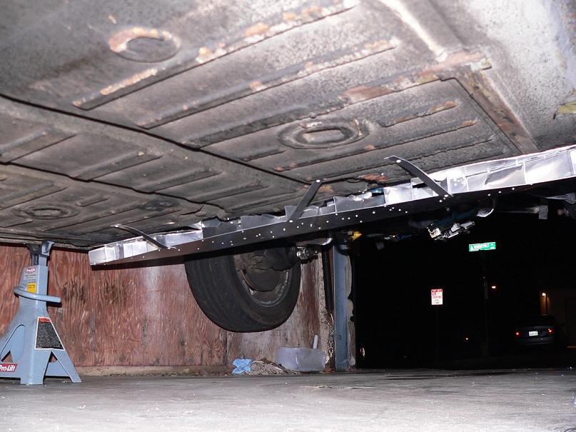
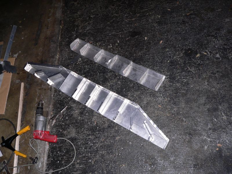
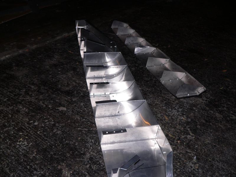
So I finally got around to redoing my scoop. The first scoop I made (pictured along with the new, bigger scoop) was actually made for the roof and was wider than the radiator opening. The new scoop is wider still, but channels all the air down to an opening of the right size. So the new scoop is 4 feet wide and sticks down from the floorpan of the car about 2 inches. So far it doesn't scrape on our huge speed bumps in the parking lot at work, so I should be okay.
Haven't tested it on the freeway yet, but it should do a little better than the old scoop. I still have some gaps and hoels to fill in where air can leak out, but this is a much nicer scoop, and should deliver more air to the radiator. I have no sheet metal brake, shear, or otherwise, so this was all made by hand with the help of a vice and some pieces of aluminum angle-iron stock. (i.e. anyone can do this) -Tony Attached thumbnail(s)  Attached image(s)  
|
| TonyAKAVW |
 Oct 25 2006, 10:48 AM Oct 25 2006, 10:48 AM
Post
#477
|
|
That's my ride.     Group: Members Posts: 2,151 Joined: 17-January 03 From: Redondo Beach, CA Member No.: 166 Region Association: None |
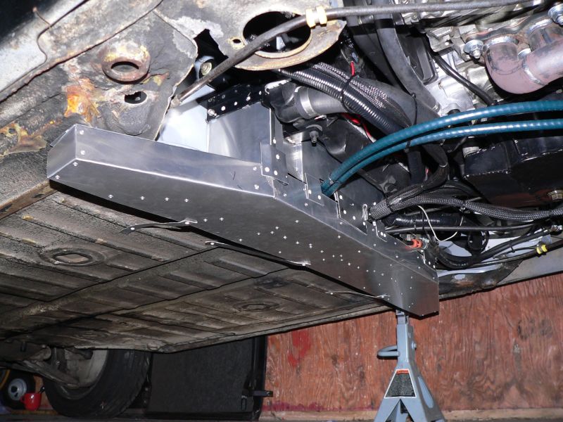
Here's the scoop and the associated duct-work from behind/below.
Attached image(s) 
|
| JPB |
 Oct 25 2006, 11:07 AM Oct 25 2006, 11:07 AM
Post
#478
|
|
The Crimson Rocket smiles in your general direction.     Group: Members Posts: 2,927 Joined: 12-November 05 From: Tapmahamock, Va. Member No.: 5,107 |
Holly road kill collector Bat Man, I think hes gonna try to stuff us through his cooling system!!!
(IMG:style_emoticons/default/beer.gif) Now that looks AWSOME Tony. I bet this thing is gonna stay way cool now. As for the gearing option, I am thinking of moving all my gears forward and taking out 1st. Third and fourth would be a straught shot forwards and back on the shifter but still need to find the parts for a new and improved 5th. That is, if i get an engins soon. |
| dmenche914 |
 Oct 25 2006, 07:22 PM Oct 25 2006, 07:22 PM
Post
#479
|
|
Senior Member    Group: Members Posts: 1,212 Joined: 27-February 03 From: California Member No.: 366 |
would a screen of some sorts be needed to prevent leaves, trash from clogging the cooling system? Me thinks this might pick up a good deal of junk off the road.
A screen would have to be fairly large in area to prevent it from getting clogged. i have a vw powered kit car (Dino replica, Kelmark GT) with basically a rear air cooled engine,and "open" firewall to the underside. I had to install a screen on the fan intake to keep leaves out. Fan screen is common on VW's that have the engine bay metal cut away (ie dune buggies, Baja Bugs, Rails etc....) just a thought, maybe with the air flow it won't matter. Real nice metal work, VERY impressive with no metal brake for its construction. |
| project-914 |
 Oct 26 2006, 09:50 PM Oct 26 2006, 09:50 PM
Post
#480
|
|
Member   Group: Members Posts: 181 Joined: 2-August 06 From: Oklahoma Member No.: 6,571 |
watch out for speedbumps...don't want to mess up that beautiful work!...
nice job |
  |
3 User(s) are reading this topic (3 Guests and 0 Anonymous Users)
0 Members:

|
Lo-Fi Version | Time is now: 7th January 2025 - 03:51 PM |
Invision Power Board
v9.1.4 © 2025 IPS, Inc.


