|
|
|
Porsche, and the Porsche crest are registered trademarks of Dr. Ing. h.c. F. Porsche AG.
This site is not affiliated with Porsche in any way. Its only purpose is to provide an online forum for car enthusiasts. All other trademarks are property of their respective owners. |
|
|

  |

| 76-914 |
 Apr 6 2014, 06:33 PM Apr 6 2014, 06:33 PM
Post
#1
|
|
Repeat Offender & Resident Subaru Antagonist  Group: Members Posts: 13,872 Joined: 23-January 09 From: Temecula, CA Member No.: 9,964 Region Association: Southern California |
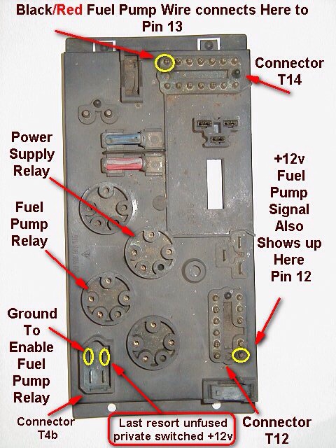
I'm going to have several electrical questions. 1st, Is pin #8, on the 14 pin plug at the relay board, the only switched 12v+ source in the engine compartment? TIA, Kent
|
   |

 
|
| Mike Bellis |
Apr 6 2014, 07:38 PM
Post
#2
|
|
Resident Electrician Group: Members Posts: 8,347 Joined: 22-June 09 From: Midlothian TX Member No.: 10,496 Region Association: None |
QUOTE(76-914 @ Apr 6 2014, 05:33 PM)  I'm going to have several electrical questions. 1st, Is pin #8, on the 14 pin plug at the relay board, the only switched 12v+ source in the engine compartment? TIA, Kent Yes, Can be used as a coil power wire when switching to carbs as well. Black wire 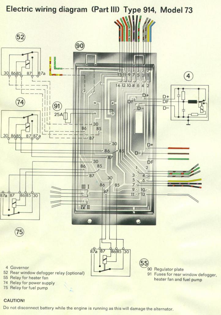 |
|
|
|
| JeffBowlsby |
Apr 6 2014, 09:48 PM
Post
#3
|
|
914 Wiring Harnesses & Beekeeper Group: Members Posts: 9,215 Joined: 7-January 03 From: San Ramon CA Member No.: 104 Region Association: None |
Careful, not all model years are the same. Check the schematic for your car.
|
 |
|
| Tom |
Apr 7 2014, 03:04 AM
Post
#4
|
|
Advanced Member Group: Members Posts: 2,139 Joined: 21-August 05 From: Port Orchard, WA 98367 Member No.: 4,626 Region Association: None |
I checked all of the schematics I can find and all have the black wires at pin #8 as switched hot from the key switch. To be safe, put a meter on it and verify that it is hot when switched on at the key switch. Battery isn't necessary to check that it would be hot. Just use one meter lead on the 4 red wires, the other on pin #8. With the key to on, you should have continuity. Key to off, open. What year car?
Tom |
|
|
|
| 76-914 |
Apr 7 2014, 06:29 AM
Post
#5
|
|
Repeat Offender & Resident Subaru Antagonist Group: Members Posts: 13,872 Joined: 23-January 09 From: Temecula, CA Member No.: 9,964 Region Association: Southern California |
QUOTE(Tom @ Apr 7 2014, 02:04 AM) I checked all of the schematics I can find and all have the black wires at pin #8 as switched hot from the key switch. To be safe, put a meter on it and verify that it is hot when switched on at the key switch. Battery isn't necessary to check that it would be hot. Just use one meter lead on the 4 red wires, the other on pin #8. With the key to on, you should have continuity. Key to off, open. What year car? Tom It's my '73 Tom, which was a 1.7 originally with your fused adapter in place. My plan is to use this wire to activate a new power relay. Glad you and Mike are here to oversee this part. |
|
|
|
| 76-914 |
Apr 7 2014, 06:37 AM
Post
#6
|
|
Repeat Offender & Resident Subaru Antagonist Group: Members Posts: 13,872 Joined: 23-January 09 From: Temecula, CA Member No.: 9,964 Region Association: Southern California |
Question #2 - Do I need to use a N/C relay off the starter circuit to kill the radiator fans when cranking/starting. I'm hoping the answer is no but thought I'd better ask now. TIA, Kent
|
|
|
|
| Tom |
Apr 7 2014, 11:37 AM
Post
#7
|
|
Advanced Member Group: Members Posts: 2,139 Joined: 21-August 05 From: Port Orchard, WA 98367 Member No.: 4,626 Region Association: None |
Kent,
Don't know why as they don't draw that much. Is the Subie ECU controlling them? If so, that feature may already be in place inside the ECU because Subaru found it to be an issue, but I don't know for sure. If you found it to be a problem, it wouldn't be that hard to remedy. A 30 amp relay wired for the starter circuit to open the fan circuit. Basically the fan power to 30, ground to 85, fan energized to 87A (NC contact), and starter power from the key switch to 86. Whenever the starter circuit is energized, the relay opens and fans have no power. Stop starting, power to fans is back. I think this would mostly depend on how much current the fans draw if the engine is hot and both are running to cool it. Say you drive 15 miles to the store and are inside 5 min and come back out. Would the fans still be running? This would also be determined on the battery condition and CCA. A battery with 500CCA will give 30 seconds of cranking at a big amperage without falling below a certain percentage of battery voltage. So if the starter is drawing 120 amps and fans 30 amps, that should not be a problem unless the battery is on the way out. Tom EDIT: Cold cranking amperes (CCA) is the amount of current a battery can provide at 0 °F (−18 °C). The rating is defined as the current a lead-acid battery at that temperature can deliver for 30 seconds and maintain at least 1.2 volts per cell (7.2 volts for a 12-volt battery). It is a more demanding test than those at higher temperatures. This is the most widely used cranking measurement for comparison purposes. |
|
|
|
| 76-914 |
Apr 7 2014, 02:33 PM
Post
#8
|
|
Repeat Offender & Resident Subaru Antagonist Group: Members Posts: 13,872 Joined: 23-January 09 From: Temecula, CA Member No.: 9,964 Region Association: Southern California |
Damn, (IMG:style_emoticons/default/chair.gif) I didn't consider that the ECU would have that covered.
|
|
|
|
| 76-914 |
Apr 28 2014, 10:28 AM
Post
#9
|
|
Repeat Offender & Resident Subaru Antagonist Group: Members Posts: 13,872 Joined: 23-January 09 From: Temecula, CA Member No.: 9,964 Region Association: Southern California |
#3 - What is the difference between a 5AG 30A fuse vs. a AGU 30A fuse. Are they interchangeable? TIA, Kent
|
|
|
|
| Tom |
Apr 28 2014, 12:18 PM
Post
#10
|
|
Advanced Member Group: Members Posts: 2,139 Joined: 21-August 05 From: Port Orchard, WA 98367 Member No.: 4,626 Region Association: None |
Kent,
The designations before the Amperage is for applications such as voltage, current flash over, and several other factors. Also designates glass enclosed or ceramic enclosed, what type of coating on the ends, etc. You would need to look each one up to determine which fuses these are meant for. This is why I stayed with ATC for my fuse blocks. It prevents someone from putting a clear glass fuse that "looks" the same in a circuit and the fuse is not rated at what the person thought. I don't know how many times I have worked on electronic equipment that some one replaced the fuse with one that looked identical until you read the inscription on the fuse that indicated it was for a 28 volt use and it was placed in a 125 volt circuit. Not good, as the fuse was no longer protecting the circuit as the proper fuse would. If you are interested in expanding your knowledge, look up "FUSEOLOGY". Very enlightening. Tom Edit: some research discovered. AG = auto glass AGU = Fast-Acting Glass Tube Midget Fuses |
|
|
|
| 76-914 |
Apr 28 2014, 06:56 PM
Post
#11
|
|
Repeat Offender & Resident Subaru Antagonist Group: Members Posts: 13,872 Joined: 23-January 09 From: Temecula, CA Member No.: 9,964 Region Association: Southern California |
Had to read thru some heavy stuff for my pea brain but I was able to learn this much. The 5 denotes it's physical size. In my case 13/32" x 1.5". That car fuses are slow blow to handle the large surges and are usually the 32V group. Now I need to take a nap. (IMG:style_emoticons/default/slits.gif)
|
|
|
|
| Dtjaden |
Apr 29 2014, 08:39 AM
Post
#12
|
|
Member Group: Members Posts: 232 Joined: 25-May 13 From: Morgan Hill, CA Member No.: 15,915 Region Association: Northern California |
The easiest location for switched 12v on the relay board is pin 1 on the 4 pin spade lug connector on the relay board. The location on the board is toward the rear on the drivers side.
 |
|
|
|
| 76-914 |
Apr 29 2014, 08:59 AM
Post
#13
|
|
Repeat Offender & Resident Subaru Antagonist Group: Members Posts: 13,872 Joined: 23-January 09 From: Temecula, CA Member No.: 9,964 Region Association: Southern California |
That could be useful info for someone that is using the relay board. I 86'd mine during the Suby conversion, however. (IMG:style_emoticons/default/biggrin.gif)
|
|
|
|
| 76-914 |
May 2 2014, 08:33 PM
Post
#14
|
|
Repeat Offender & Resident Subaru Antagonist Group: Members Posts: 13,872 Joined: 23-January 09 From: Temecula, CA Member No.: 9,964 Region Association: Southern California |
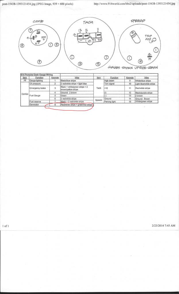
#4- I need to tie in my alt light with the suby engine. I have a single wire from the Suby to connect to the GEN light but don't know where to tie it in. I looked at Jeff B's info (thx Jeff) and found which bulb it is and there are 2 wires. A R/W and a G/R wire. The R/W goes to fuse 9 and to other gage bulbs so I can rule that one out. Maybe a switched + for bulb power? That leaves me with the G/R which goes to the relay board #5 on the 14 pin plug then out the 12 pin #1 to the OIL pressure switch. I don't understand this.
|
|
|
|
| Dave_Darling |
May 2 2014, 10:07 PM
Post
#15
|
|
914 Idiot Group: Members Posts: 15,331 Joined: 9-January 03 From: Silicon Valley / Kailua-Kona Member No.: 121 Region Association: Northern California |
Green/red would be the oil pressure light, not the alternator light.
That one has a blue wire and a red/white wire. The red/white supplies +12V, while the blue wire connects to the D+ wire coming from the alternator to the voltage regulator. --DD |
|
|
|
| Mike Bellis |
May 2 2014, 11:40 PM
Post
#16
|
|
Resident Electrician Group: Members Posts: 8,347 Joined: 22-June 09 From: Midlothian TX Member No.: 10,496 Region Association: None |
The alternator lamp work with 2 positive leads. One is switched from the key, through a fuse and to the lamp. The other is the D+ from the alternator. When the alternator spins and creates voltage (2nd positive) the dash lamp turns off. When the engine is not running, the D+ turns "less positive" and the lamp lights up.
|
|
|
|
| Tom |
May 3 2014, 01:32 AM
Post
#17
|
|
Advanced Member Group: Members Posts: 2,139 Joined: 21-August 05 From: Port Orchard, WA 98367 Member No.: 4,626 Region Association: None |
That red/white that goes to fuse #9 on the fused side is the correct wire for one side of the alt bulb. The other side is a blue wire that goes to the alternator at D+.
Tom |
|
|
|
| 76-914 |
May 3 2014, 10:10 AM
Post
#18
|
|
Repeat Offender & Resident Subaru Antagonist Group: Members Posts: 13,872 Joined: 23-January 09 From: Temecula, CA Member No.: 9,964 Region Association: Southern California |
Odd. I have one sch showing GR yet today I find the one you mention w/ Blue on another print out in Jeff material. Are there two and I have the wrong one?? Many TY's for the assistance, guy's. (IMG:style_emoticons/default/WTF.gif)
 |
|
|
|
| JeffBowlsby |
May 3 2014, 11:05 AM
Post
#19
|
|
914 Wiring Harnesses & Beekeeper Group: Members Posts: 9,215 Joined: 7-January 03 From: San Ramon CA Member No.: 104 Region Association: None |
QUOTE(76-914 @ May 3 2014, 09:10 AM) Odd. I have one sch showing GR yet today I find the one you mention w/ Blue on another print out in Jeff material. Are there two and I have the wrong one?? Many TY's for the assistance, guy's. (IMG:style_emoticons/default/WTF.gif) That diagram was superseded., it was not correct. I try to keep the website materials correct, and I replaced that former diagram on the website in May 2013 with this corrected one. Keep in mind that this diagram is only for the 1974 model years, other years are different: Attached image(s) 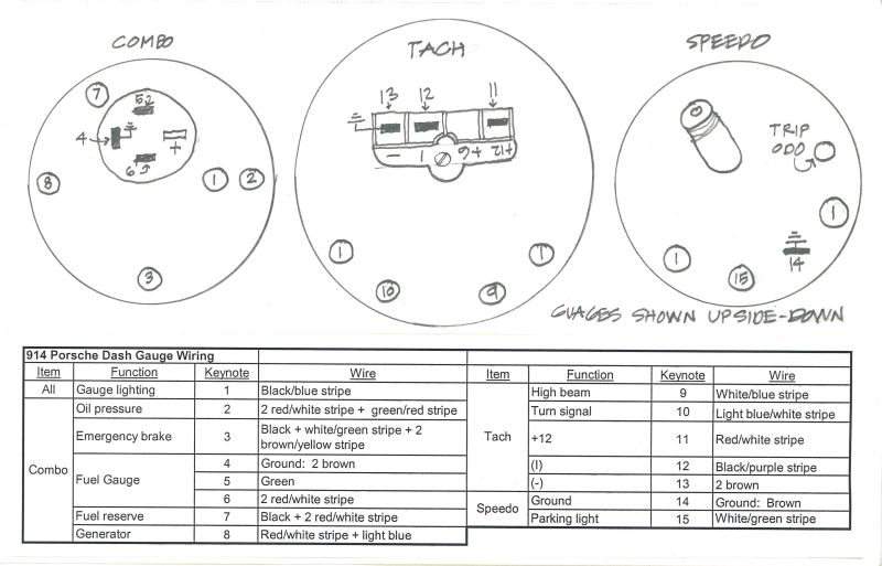
|
|
|
|
| 76-914 |
Jun 4 2014, 01:54 PM
Post
#20
|
|
Repeat Offender & Resident Subaru Antagonist Group: Members Posts: 13,872 Joined: 23-January 09 From: Temecula, CA Member No.: 9,964 Region Association: Southern California |
#5 - If you own a 914 you know the importance of a good ground. As I went through the Subaru harness I counted over 20 grounding points so Suby has a good idea, also.
My question is this. Are there rules that govern grounds? If so, can a layman understand them? Can a ground junction become ineffective if too many grounds converge at one point? Does a ground need to be sized? Should it be the same gauge as the positive circuit it completes? If adding ground points does the material type matter? e.g. brass, steel. As always, TIA, Kent |
|
|
|
|
2 User(s) are reading this topic (2 Guests and 0 Anonymous Users)
0 Members:

|
Lo-Fi Version | Time is now: 20th March 2026 - 08:06 PM |
Invision Power Board
v9.1.4 © 2026 IPS, Inc.