|
|

|
Porsche, and the Porsche crest are registered trademarks of Dr. Ing. h.c. F. Porsche AG.
This site is not affiliated with Porsche in any way. Its only purpose is to provide an online forum for car enthusiasts. All other trademarks are property of their respective owners. |
|
|
  |
| ChrisFoley |
 Dec 16 2005, 06:19 PM Dec 16 2005, 06:19 PM
Post
#1
|
|
I am Tangerine Racing      Group: Members Posts: 7,981 Joined: 29-January 03 From: Bolton, CT Member No.: 209 Region Association: None 
|
Specifically I am looking for rotational stiffness (ie. twist) of the trailing arm due to the tire contact patch resisting sideways sliding of the car. I'm only interested in forces greater than 1G during cornering.
I already know what happens but go ahead and take a guess. (IMG:style_emoticons/default/biggrin.gif) I'll post pictures of my test fixture shortly. |
| TimT |
 Dec 16 2005, 06:25 PM Dec 16 2005, 06:25 PM
Post
#2
|
|
retired     Group: Members Posts: 4,033 Joined: 18-February 03 From: Wantagh, NY Member No.: 313 |
Chris the trailing arm appears to be a pretty stout piece. Im interested in your info, and I could maybe model a trailing arm on a FEA program that I have..
lemme find the FEA output I did for my 911 roll cage |
| J P Stein |
 Dec 16 2005, 06:26 PM Dec 16 2005, 06:26 PM
Post
#3
|
|
Irrelevant old fart      Group: Members Posts: 8,797 Joined: 30-December 02 From: Vancouver, WA Member No.: 45 Region Association: None |
WAG:
1 deg @500 lbs. I'm assuming you're trying to twist it. |
| airsix |
 Dec 16 2005, 07:09 PM Dec 16 2005, 07:09 PM
Post
#4
|
|
I have bees in my epiglotis     Group: Members Posts: 2,196 Joined: 7-February 03 From: Kennewick Man (E. WA State) Member No.: 266 |
What exactly do you mean by "1G". I'm sure you don't mean a force equal to the weight of the trailing arm. (IMG:http://www.914world.com/bbs2/html/emoticons/laugh.gif) Do you mean something like a force equal to 1/2 the weight of the car with a moment arm equal to the radius of the tire/wheel combo? Are you measuring deflection of a rigidly monted trailing arm, or are we including bushing flex too?
By the way, this is a cool thread. Can't wait to hear about your experiment. Good stuff. -Ben M. |
| ppickerell |
 Dec 16 2005, 07:41 PM Dec 16 2005, 07:41 PM
Post
#5
|
|
914 addicted    Group: Members Posts: 1,679 Joined: 14-October 03 From: Pleasanton, CA. Member No.: 1,246 |
Chris,
Do you intend to test before and after boxing? |
| Dave_Darling |
 Dec 16 2005, 07:54 PM Dec 16 2005, 07:54 PM
Post
#6
|
|
914 Idiot                Group: Members Posts: 15,151 Joined: 9-January 03 From: Silicon Valley / Kailua-Kona Member No.: 121 Region Association: Northern California 
|
I'm guessing that most of the flex happens in the tube where the pivot shaft sits, not in the box section of the arm.
--DD |
| spare time toys |
 Dec 16 2005, 08:08 PM Dec 16 2005, 08:08 PM
Post
#7
|
|
hooked on grilling food.     Group: Members Posts: 4,059 Joined: 3-April 04 From: West Plano Tx Member No.: 1,884 Region Association: Southwest Region |
My guess is it has flex designed into it at an amount equal to slightly less than the tensel strength of the material from which it was made. IE it will bend before it will snap like an airplane wing (IMG:http://www.914world.com/bbs2/html/emoticons/unsure.gif)
|
| ChrisFoley |
 Dec 16 2005, 08:24 PM Dec 16 2005, 08:24 PM
Post
#8
|
|
I am Tangerine Racing      Group: Members Posts: 7,981 Joined: 29-January 03 From: Bolton, CT Member No.: 209 Region Association: None 
|
So far JP is the only one really on the right track. (IMG:style_emoticons/default/smile.gif)
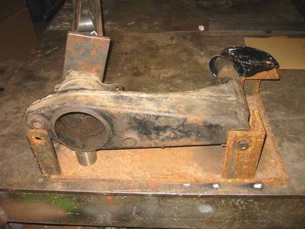
You're only off by a factor of two. What I did was mount the trailing arm pivot shaft in a support fixture I fabricated. Then I welded the base plate of the fixture to my 800lb welding bench. Attached image(s) 
|
| ChrisFoley |
 Dec 16 2005, 08:26 PM Dec 16 2005, 08:26 PM
Post
#9
|
|
I am Tangerine Racing      Group: Members Posts: 7,981 Joined: 29-January 03 From: Bolton, CT Member No.: 209 Region Association: None 
|
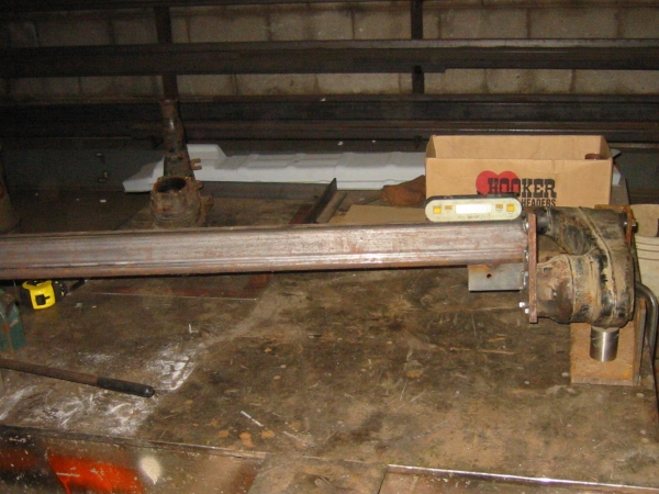
Then I attached a 5ft piece of structural tubing to the side of the trailing arm where the bearing retainer bolts on.
Attached image(s) 
|
| ChrisFoley |
 Dec 16 2005, 08:32 PM Dec 16 2005, 08:32 PM
Post
#10
|
|
I am Tangerine Racing      Group: Members Posts: 7,981 Joined: 29-January 03 From: Bolton, CT Member No.: 209 Region Association: None 
|
by putting a 200lb man's weight at the end of the structural tube I can simulate a 1000lb twisting force on the trailing arm.
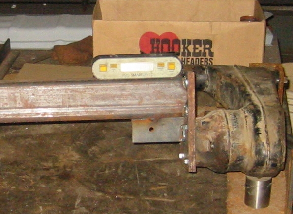
By my rough calculations this is somewhere in the ball park of what happens when a slick shod race car goes around a corner at 1G+. Keeping in mind that the contact patch is roughly 1ft away from the axis of the wheel and the slicks allow a car to corner at close to 1.5G. The digital level is on the structural tube to measure the rotational deflection of the trailing arm in 0.1 degree increments. |
| ChrisFoley |
 Dec 16 2005, 08:34 PM Dec 16 2005, 08:34 PM
Post
#11
|
|
I am Tangerine Racing      Group: Members Posts: 7,981 Joined: 29-January 03 From: Bolton, CT Member No.: 209 Region Association: None 
|
I had a friend sit on the end of the tube and saw the level move by one full degree! (IMG:style_emoticons/default/ohmy.gif)
Attached image(s) 
|
| ChrisFoley |
 Dec 16 2005, 08:40 PM Dec 16 2005, 08:40 PM
Post
#12
|
|
I am Tangerine Racing      Group: Members Posts: 7,981 Joined: 29-January 03 From: Bolton, CT Member No.: 209 Region Association: None 
|
I have several more tests planned already.
1) measure a trailing arm with the standard box kit installed. 2) measure a trailing arm with my idea of a better stiffener. * 3) measure the fore/aft deflection of the arm by applying the load 90 degrees to what I did for this test. This will simulate what happens under 1G of braking force. * My better stiffener will be very simple, lightweight, and will allow me to make a camber change to the trailing arm at the same time. (IMG:style_emoticons/default/smile.gif) I just need to make another fixture so I can weld it together with the correct geometry. (IMG:style_emoticons/default/welder.gif) |
| TimT |
 Dec 16 2005, 08:41 PM Dec 16 2005, 08:41 PM
Post
#13
|
|
retired     Group: Members Posts: 4,033 Joined: 18-February 03 From: Wantagh, NY Member No.: 313 |
Put the level on the trailing arm, not the lever
let all pieces be at rest, zero the level, given the odd profile of the trailing arm.. maybe some foam or balsa wood will be needed to make a suitable platform for the level the reason I say this is there is deflection/movement in the plate that you bolted to the bearing keeper In all testing and modeling are good... 1 deg at 1G wonder what they were designed for ? |
| TimT |
 Dec 16 2005, 08:42 PM Dec 16 2005, 08:42 PM
Post
#14
|
|
retired     Group: Members Posts: 4,033 Joined: 18-February 03 From: Wantagh, NY Member No.: 313 |
and yes I see the angle you have welded on the botton of the setup
|
| SpecialK |
 Dec 16 2005, 08:43 PM Dec 16 2005, 08:43 PM
Post
#15
|
|
aircraft surgeon     Group: Benefactors Posts: 3,211 Joined: 15-March 04 From: Pacific, MO Member No.: 1,797  |
....go on.... (IMG:http://www.914world.com/bbs2/html/emoticons/idea.gif)
So can you tell with your set-up which area was/is most susceptible to torsional loads? e.i.- where would "beefing it" by most effective? p.s. - someone mentioned FEA software earlier in this post. I'm still in the process of honing my CAD skills, and found a company that has a "free", limited (can't import CAD files, but has a descent CAD program attached), 300 node version of their software for engineers. I downloaded it a couple of weeks ago, but haven't had time to mess with it too much yet. Free FEA software The 300-node version is about 2/3's of the way down the page. |
| andys |
 Dec 16 2005, 08:57 PM Dec 16 2005, 08:57 PM
Post
#16
|
|
Advanced Member     Group: Members Posts: 2,165 Joined: 21-May 03 From: Valencia, CA Member No.: 721 Region Association: None 
|
Chris,
This is exactly the kind of testing required to provide a benchmark by which to compare against. My custom trailing arms took so much effort fabricate that by the time I was finished, I was frankly too burned out to continue on with making a test fixture. I'm glad you're doing it!! Unless you intend on making the stock trailing arm your "standard", you'll otherwise need to qualify your fixture. If you don't, then your data will be flawed (unfortunately). You'll need to first determine how much the test fixture deflects under load. Don't get me wrong, cause it's always seemingly easy to blow holes in someone elses work, but that's not my intention. Continue on, and do share your results; I remain very interested in your work. Are you going to test to fail? I think if you examine the stock trailing arm design, I think you'll find it quite good (from a design standpoint). The design of course, was dictated by production requirements, but it is still very good. The area I never liked, was the pivot shaft and how it ties into the chassis mounts. Think about the camber and toe adjustment. You must deflect the inner ear in order to move it around. I've seen where some try to re-inforce the inner ear, only to have it crack. In my opinion, the inner ear is just crying for a spherical joint or conformal structure of some kind......sorry, guess I'm getting a little OT. Andys |
| goose2 |
 Dec 16 2005, 09:06 PM Dec 16 2005, 09:06 PM
Post
#17
|
|
Senior Member    Group: Members Posts: 976 Joined: 30-March 05 From: Eugene, Oregon Member No.: 3,847 Region Association: Pacific Northwest |
If you mount the level in various locations on the trailing arm...gobs of modeling clay would work....then load the lever arm....you'll be able to factor out any mounting plate flex while determining where the actual flex is occurring.
|
| TimT |
 Dec 16 2005, 09:12 PM Dec 16 2005, 09:12 PM
Post
#18
|
||
|
retired     Group: Members Posts: 4,033 Joined: 18-February 03 From: Wantagh, NY Member No.: 313 |
Yes.. but I wonder how much the chassis yields? chasing the dragon.. very cool |
||
| rick 918-S |
 Dec 16 2005, 09:21 PM Dec 16 2005, 09:21 PM
Post
#19
|
|
Hey nice rack! -Celette                Group: Members Posts: 20,928 Joined: 30-December 02 From: Now in Superior WI Member No.: 43 Region Association: Northstar Region 

|
Put that level at the in board mounting in the direction of the pivot bolt and see what happens.
|
| URY914 |
 Dec 16 2005, 09:21 PM Dec 16 2005, 09:21 PM
Post
#20
|
|
I built the lightest 914 in the history of mankind.                                                                                                     Group: Members Posts: 126,198 Joined: 3-February 03 From: Jacksonville, FL Member No.: 222 Region Association: None |
Chris,
This is what the pro teams call "off season testing". P |
  |
1 User(s) are reading this topic (1 Guests and 0 Anonymous Users)
0 Members:

|
Lo-Fi Version | Time is now: 26th April 2025 - 03:11 AM |
Invision Power Board
v9.1.4 © 2025 IPS, Inc.


