|
|
|
Porsche, and the Porsche crest are registered trademarks of Dr. Ing. h.c. F. Porsche AG.
This site is not affiliated with Porsche in any way. Its only purpose is to provide an online forum for car enthusiasts. All other trademarks are property of their respective owners. |
|
|


| Tom |
 May 3 2014, 01:30 PM May 3 2014, 01:30 PM
Post
#1
|
|
Advanced Member  Group: Members Posts: 2,139 Joined: 21-August 05 From: Port Orchard, WA 98367 Member No.: 4,626 Region Association: None |
After reading many accounts of how this circuit works, I felt compelled to investigate further as I did not understand how two positives would cause a light to operate. They won't. One must be somewhat negative to complete the circuit. Internet searches turned up the same basic explanation, still was not buying it. I think it was being oversimplified.
This is how I think the alt light works: When the key is on and engine not running, there is 12 volts + at the alt light power side coming from the fused side of fuse #9. The other side goes to a junction on the relay board with D+. With the key to off and a meter connected between D+ and ground at the relay board, the reading is 12 ohms. As soon as the key is turned to on, the reading jumps to 12.5 meg ohms and the light comes on. If the wire for D+ to the alt is removed, the reading stays the same and the light stays on. Removing the VR caused the reading to jump to infinity and the light goes out. For the light to work, there has to be power to one side of the light and some resistance reading to ground for the other. Looking at the wiring diagram, one can follow the blue wire to the junction at the relay board at D+, then up thru the VR to a set of relay contacts, then down thru a ( resistor ?, not sure) and then down to the DF connection and on to the rotor where the current will produce a magnetic field. After the rotor, it goes to ground. When the alt spins enough RPM's, a voltage is produced and fed back to the VR, causing the relay to open and removes the ground path for the alt light. I could be entirely wrong here, but this is what I see and my readings more or less confirm it. If you see an error in my thinking, please post and let me know. Thanks, Tom Attached thumbnail(s) 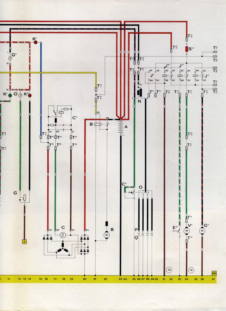
|
   |

 
|
  |
Replies(1 - 19)
| bulitt |
May 3 2014, 01:47 PM
Post
#2
|
|
Achtzylinder Group: Members Posts: 4,188 Joined: 2-October 11 Member No.: 13,632 Region Association: South East States |
I recall you need a light or resistor to "excite" the alternator into producing power particularly at low engine speeds. As you stated, once the power is flowing the light drops out???
|
|
|
|
| toolguy |
May 3 2014, 02:38 PM
Post
#3
|
|
Senior Member Group: Members Posts: 1,273 Joined: 2-April 11 From: San Diego / El Cajon Member No.: 12,889 Region Association: Southern California |
Light comes on when the alternator out voltage on the red lead is lower than the battery voltage. . reverse polarity flow. . .
Red white is switched battery 12.5 or so. . that is what lights the bulb at idle. . the bulb is connected to potential lower than 12 .5 volts thru the diodes in the alternator. . with the alternator turning, the voltage out of the alternator on the Blue wire to the regulator reaches the same voltage as the red [B+] out to the battery so there is no differentiation in voltage so no flow anymore thru the light and the light dims. both side now being equal voltage. . . and yes, the alternator needs voltage to excite the fields to begin the charging cycle. spinning an alternator without hooking up a batter will not produce voltage. . generators did it by having magnets in the outside fields. . Really simplified version. .left out the technical stuff. It's only confusing |
 |
|
| Spoke |
May 3 2014, 03:47 PM
Post
#4
|
|
Jerry Group: Members Posts: 7,047 Joined: 29-October 04 From: Allentown, PA Member No.: 3,031 Region Association: None |
QUOTE(Tom @ May 3 2014, 03:30 PM)  I could be entirely wrong here, but this is what I see and my readings more or less confirm it. If you see an error in my thinking, please post and let me know. Thanks, Tom Your findings are correct. The GEN light has 2 functions: 1) Indicate when the main charging path is not functioning correctly. There are 2 charging paths (see diagram). The one on the left powers the voltage regulator. The path on the right is the main path and powers the vehicle's electrical circuits and charges the battery. The GEN light is connected between these 2 paths. If the main path isn't providing enough voltage, there will be a difference of voltage across the GEN light and it will light up. 2) Provide the minute current necessary (when the engine is first started) to energize the magnet in the armature (the part of the alternator that turns). This is called bootstrapping since the alternator pulls its voltage up by its own generated voltage. #2 above is why if the GEN light is burned out or missing the alternator may fail to start up. It is possible for the alternator to start up since the armature magnet may have some residual magnetism when the engine is off. |
|
|
|
| Dave_Darling |
May 3 2014, 04:24 PM
Post
#5
|
|
914 Idiot Group: Members Posts: 15,042 Joined: 9-January 03 From: Silicon Valley / Kailua-Kona Member No.: 121 Region Association: Northern California |
A couple of minor misconceptions in the OP:
The light does not need voltage on one side and ground on the other to light. It needs more voltage on one side than on the other--and it doesn't really care which side is higher and which is lower. The thing at the alternator is not a resistor, it is a diode. It keeps the current from flowing "backwards" through it except under some specific circumstances. Toolguy and Spoke both have the functions correct. When you turn the key on with the engine not running, the red/white wire gets +12V. Since the alternator isn't spinning, the wire coming from it has about 0V. Current flows from +12V to 0V through the bulb, and the bulb lights up. When the engine is running, the alternator produces voltage. So the blue wire from the alt will be at about +12V, as will the red/white wire. No current will flow, so no light. Note that you can get resistance on some connections that drops some of the voltage on one side or the other of those, which will make the light glow faintly; and there are other failure modes that will make the light shine in different ways. And yes, the light provides resistance to help "bootstrap" the alternator so that it starts charging. --DD |
|
|
|
| 76-914 |
May 3 2014, 04:50 PM
Post
#6
|
|
Repeat Offender & Resident Subaru Antagonist Group: Members Posts: 13,608 Joined: 23-January 09 From: Temecula, CA Member No.: 9,964 Region Association: Southern California |
(IMG:style_emoticons/default/wacko.gif) Wow! I'm still a little dazed but that was some "on point" info. I'm glad you guys filtered "toolguy's" simplified version. (IMG:style_emoticons/default/lol-2.gif) Thanks a million. (IMG:style_emoticons/default/pray.gif)
|
|
|
|
| worn |
May 3 2014, 07:47 PM
Post
#7
|
|
can't remember Group: Members Posts: 3,279 Joined: 3-June 11 From: Madison, WI Member No.: 13,152 Region Association: Upper MidWest |
QUOTE(Tom @ May 3 2014, 11:30 AM) After reading many accounts of how this circuit works, I felt compelled to investigate further as I did not understand how two positives would cause a light to operate. They won't. One must be somewhat negative to complete the circuit. Internet searches turned up the same basic explanation, still was not buying it. I think it was being oversimplified. This is how I think the alt light works: When the key is on and engine not running, there is 12 volts + at the alt light power side coming from the fused side of fuse #9. The other side goes to a junction on the relay board with D+. With the key to off and a meter connected between D+ and ground at the relay board, the reading is 12 ohms. As soon as the key is turned to on, the reading jumps to 12.5 meg ohms and the light comes on. If the wire for D+ to the alt is removed, the reading stays the same and the light stays on. Removing the VR caused the reading to jump to infinity and the light goes out. For the light to work, there has to be power to one side of the light and some resistance reading to ground for the other. Looking at the wiring diagram, one can follow the blue wire to the junction at the relay board at D+, then up thru the VR to a set of relay contacts, then down thru a ( resistor ?, not sure) and then down to the DF connection and on to the rotor where the current will produce a magnetic field. After the rotor, it goes to ground. When the alt spins enough RPM's, a voltage is produced and fed back to the VR, causing the relay to open and removes the ground path for the alt light. I could be entirely wrong here, but this is what I see and my readings more or less confirm it. If you see an error in my thinking, please post and let me know. Thanks, Tom Originally key on, engine not lit, the battery feeds current throgh light tobthe D+ which is simply a path through the windings to ground because theregulator has D+ linked directly to Df. This current magnetizes the Df windings and when the spinning starts D+ becomes 13 volts really soon. That balances the battery and the light goes off. If there is a failure in the diodes charging the battery, the battery will go low, D+ will stay high and now the light will come on with electrons flowing in the opposite direction. If the original lamp wattage is too low, below 1.2 watts, it is possible that you wont bootstrap Df with enough current. |
|
|
|
| stugray |
May 3 2014, 09:21 PM
Post
#8
|
|
Advanced Member Group: Members Posts: 3,825 Joined: 17-September 09 From: Longmont, CO Member No.: 10,819 Region Association: None |
Every one else covered the basics very well above.
One statement in the OP's explanation jumped out at me though: QUOTE With the key to off and a meter connected between D+ and ground at the relay board, the reading is 12 ohms. As soon as the key is turned to on, the reading jumps to 12.5 meg ohms and the light comes on. You cannot measure the resistance of a powered circuit. So trying to explain the difference in resistance to ground before & after energizing the circuit is not measureable with a DMM in resistance mode. |
|
|
|
| Tom |
May 4 2014, 12:44 PM
Post
#9
|
|
Advanced Member Group: Members Posts: 2,139 Joined: 21-August 05 From: Port Orchard, WA 98367 Member No.: 4,626 Region Association: None |
stugray,
OMG, you are so right! I don't know what I was thinking yesterday. I do know that you can't take resistance readings with power applied. Must have forgot yesterday. Dave_Darling, The light must have a path to ground, even if there is a resistance between the light and ground. I measured 12 ohms initially. I was talking about the two rectangular "boxes" in the voltage regulator. They don't look like diodes. One is all blacked in, the other is left uncolored or clear. I am thinking they are resistors. toolguy, The light doesn't get connected to a potential less than 12.5 volts thru the diodes, it's connected thru the voltage regulator and then thru the field to ground. I still think the relay in the voltage regulator has the major part in keeping the light off when there is voltage being produced by the alternator. With the normally closed contacts open, there is no path for the light negative side to get to ground. I guess it is like the chicken or the egg. If no voltage is present, light lights, if there is voltage present, the relay operates opening the path to ground, but the light would not light anyway as the two voltages would be the same. Although, looking at the regulation side of the circuit, if the relay did not close and remove the ground, it would be almost like the initial "bootstrapping" was in place and the alternator would not vary it 's output to keep up with demands, so the relay does have an important part in this circuit. I guess I am just being too technical, but when I see something I don't fully understand, I reach out to the guys who may have the answer for me. Often times I have found out information that has helped me in other projects. Thanks for the reply, Tom |
|
|
|
| type47 |
Aug 26 2014, 06:41 AM
Post
#10
|
|
Viermeister Group: Members Posts: 4,254 Joined: 7-August 03 From: Vienna, VA Member No.: 994 Region Association: MidAtlantic Region |
QUOTE(Dave_Darling @ May 3 2014, 02:24 PM) ... and there are other failure modes that will make the light shine in different ways. Could you expand on this? My alt light just came on (and I changed the alt for a tested good one about 6 weeks ago); fan belt still tight; no obvious observed problems so I removed the alt and took it to the free FLAPS for testing and it tested good. Great (IMG:style_emoticons/default/dry.gif) good alt but the alt light is lit. Need things to check. Now that the alt is out, I'll check the alt harness and the 14 pin harness on the relay board. Want to drive to a local event this Sat so I'd like this resolved. TIA. |
|
|
|
| ThePaintedMan |
Aug 26 2014, 07:46 AM
Post
#11
|
|
Advanced Member Group: Members Posts: 3,886 Joined: 6-September 11 From: St. Petersburg, FL Member No.: 13,527 Region Association: South East States |
Check the voltage regulator.
|
|
|
|
| stugray |
Aug 26 2014, 08:05 AM
Post
#12
|
|
Advanced Member Group: Members Posts: 3,825 Joined: 17-September 09 From: Longmont, CO Member No.: 10,819 Region Association: None |
There is a test where you unplug the VR and connect two pins on the harness side and start the car and measure the ALT output voltage.
I dont remember which pins, but I have it written down at home (a serach on here might turn it up). Anyway, I had a problem where I was barely getting above 13 Volts with the car running. I did the test, and the ALT was putting out 16 Volts with the VR bypassed. I put in a different (still used) VR and then I was getting 14.5 Volts running. So that check can tell you if the problem is with the Alt or the VR. |
|
|
|
| Dave_Darling |
Aug 26 2014, 09:23 AM
Post
#13
|
|
914 Idiot Group: Members Posts: 15,042 Joined: 9-January 03 From: Silicon Valley / Kailua-Kona Member No.: 121 Region Association: Northern California |
QUOTE(type47 @ Aug 26 2014, 05:41 AM) Could you expand on this? If some of your alternator's diodes are failing the light will flicker. If there is resistance in the circuit, the light can come on dimly. There is some other failure mode that makes the light dim at idle, and get brighter as the RPMs increase. (Failed VR? I forget!) And there may be others as well. I used to be able to find a chart with different light behaviors and possible causes, but I can't find it now... --DD |
|
|
|
| type47 |
Aug 26 2014, 10:33 AM
Post
#14
|
|
Viermeister Group: Members Posts: 4,254 Joined: 7-August 03 From: Vienna, VA Member No.: 994 Region Association: MidAtlantic Region |
The alt I removed this morning and tested good has been reinstalled. Just have to connect the starter connection and reinstall the heating ducts and air guide. Funny, I have a VR sitting out on the tool table so I might as well try that too. Break for lunch ... BLT's!
Rats! All put back together and Alt light still on; changed VR, still on ... no power to oil temp gauge and step on brakes, alt light gets brighter, tach indicates less rpm than it sounds like. Going to check brake light switch wiring circuit ... So, after looking at the schematic, I decided to check out fuse #9 with it's circuit to the tach, brake light switch, fuel gauge, etc. Fuse was blown. Replace fuse, all is good (except to figure out why the fuse blew, but I'm beat and no more today). Moral of the story: If your alt warning light goes on, check #9 fuse before you R & R the alternator. (IMG:style_emoticons/default/ar15.gif) |
|
|
|
| type47 |
Sep 5 2014, 09:21 AM
Post
#15
|
|
Viermeister Group: Members Posts: 4,254 Joined: 7-August 03 From: Vienna, VA Member No.: 994 Region Association: MidAtlantic Region |
So, there is no joy in Mudville, the alt light is still on. I installed a new solid state VR and the light is still on. I think i need to test/measure voltages at the alt warning light; the blue wire and the red/white wires as it seems the explanations have the +12 V from those 2 wires controlling the light operation.
|
|
|
|
| Spoke |
Sep 5 2014, 10:27 AM
Post
#16
|
|
Jerry Group: Members Posts: 7,047 Joined: 29-October 04 From: Allentown, PA Member No.: 3,031 Region Association: None |
Alternator testing good may not completely test all the functions of the alternator. Not sure the test would find a damaged diode on the charging or VR sides.
Here's a little description of how the diodes work in the alternator. The alternator is a 3-phase alternator with 3 separate windings spaced 120 degrees from each other. With full diode bridge rectification, the correct alternator output across the VR would look something like this. The black line is actual voltage since the VR has some capacitance to filter the ripple voltage from the alternator. 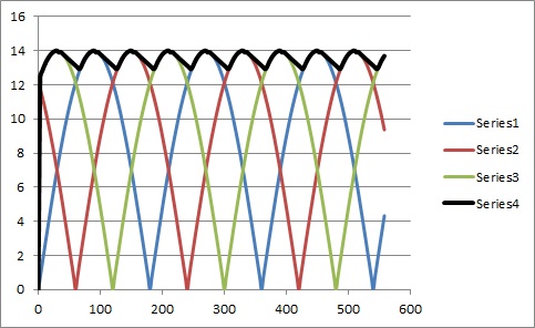 If you lose one phase of the alternator because of a open circuited diode, the voltage would droop between the operating phases and the GEN light would light a bit. 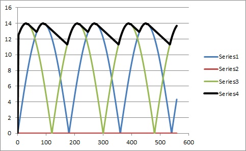 If 2 phases are lost, the droop in the voltage is more pronounced and the GEN light is brighter. 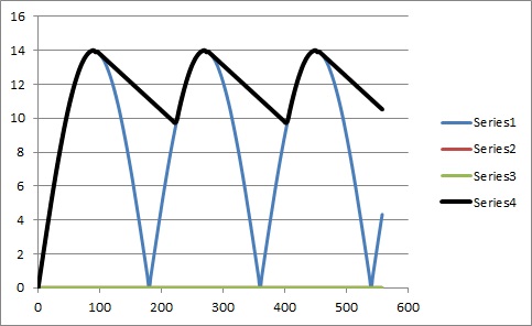 So with burnt diodes, the GEN light is on at idle, rev the engine and the GEN light dims. This is because there is less time between active phases of the black trace, the voltage across the VR and one side of the GEN light is almost 14V like across the battery on the other side of the GEN light. 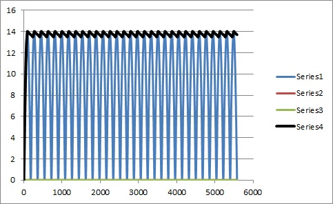 |
|
|
|
| type47 |
Sep 5 2014, 03:21 PM
Post
#17
|
|
Viermeister Group: Members Posts: 4,254 Joined: 7-August 03 From: Vienna, VA Member No.: 994 Region Association: MidAtlantic Region |
QUOTE(Spoke @ Sep 5 2014, 08:27 AM) Alternator testing good may not completely test all the functions of the alternator. Not sure the test would find a damaged diode on the charging or VR sides. Tested at Advance Auto parts. I really don't want to R & R the alt again. When I started and revved the engine, the light did not dim. I need to get out and measure voltages on either side of the alt light. I think I can get the DMM probe in the plugs. First try did not get 12 V but about 3 V. Had to stop for other things ... So on either side of the alt light there should be 12 V? That's what I read from the above info. So the alt terminal D+ found in track 76 in the schematic should be 12 V. The terminals T 3a, T 3b are the plug for the alt harness on the relay board and T 14/2 connects there too; I should be able to measure at the plug... |
|
|
|
| Spoke |
Sep 5 2014, 04:02 PM
Post
#18
|
|
Jerry Group: Members Posts: 7,047 Joined: 29-October 04 From: Allentown, PA Member No.: 3,031 Region Association: None |
Remove the gauge bucket with the GEN light. Start the car. Measure the voltage on both sides of the GEN light to ground.
One side should be the battery voltage about 13-14V. The other side should be the same but will likely be lower. If the one side is lower, likely there is an issue with the alternator (or wiring). I threw in the (or wiring) because a wire issue could cause just about any odd behavior. When did the GEN light start lighting up? Did you do any work to the car before? BTW, what is the battery voltage when the car is idling? |
|
|
|
| TheCabinetmaker |
Sep 5 2014, 04:10 PM
Post
#19
|
|
I drive my car everyday Group: Members Posts: 8,309 Joined: 8-May 03 From: Tulsa, Ok. Member No.: 666 |
Last time I saw a bad vr I replaced it with the solid state unit. It would not work. Replaced it with a new oem hella and all was well.
|
|
|
|
| type47 |
Sep 5 2014, 05:29 PM
Post
#20
|
|
Viermeister Group: Members Posts: 4,254 Joined: 7-August 03 From: Vienna, VA Member No.: 994 Region Association: MidAtlantic Region |
QUOTE(The Cabinetmaker @ Sep 5 2014, 02:10 PM) Last time I saw a bad vr I replaced it with the solid state unit. It would not work. Replaced it with a new oem hella and all was well. I have a bunch of VR's laying around so I could try them. Spoke, the Alt light lit up ~2 weeks ago. Blew #9 fuse and when I replaced the fuse, it seemed all was OK (see posts above that are about this). I have been working on the car but not on the electrical. I've been trying to get a CIS system to work. Only related things are a 009 dizzy with Pertronix. I've looked for shorts, I have the gauge cluster out and will measure on both sides of the alt light. I even took the brake light bulbs out and Dremel wire wheeled the surfaces wondering if oxidation was the culprit. Thanks for the ideas and I'd appreciate any explanations and thoughts. Probably won't get to do any work 'til Sunday. Going for PA peaches at Brown's in Loganville, PA tomorrow (SO quality time). |
|
|
|
|
1 User(s) are reading this topic (1 Guests and 0 Anonymous Users)
0 Members:

|
Lo-Fi Version | Time is now: 16th September 2024 - 12:50 PM |
Invision Power Board
v9.1.4 © 2024 IPS, Inc.