|
|

|
Porsche, and the Porsche crest are registered trademarks of Dr. Ing. h.c. F. Porsche AG.
This site is not affiliated with Porsche in any way. Its only purpose is to provide an online forum for car enthusiasts. All other trademarks are property of their respective owners. |
|
|
| VaccaRabite |
 Jul 8 2009, 11:15 AM Jul 8 2009, 11:15 AM
Post
#1
|
|
En Garde!           Group: Admin Posts: 13,636 Joined: 15-December 03 From: Dallastown, PA Member No.: 1,435 Region Association: MidAtlantic Region 
|
Jake's site is down it seems, so I am going to ask this here.
I am about to set my pushrod geometry, but I am having a brain fart. Do I use the peak cam lift or the peak valve lift. I think that it has to be within 5% of peak valve lift, but I am just not sure, and I don't want to mess it up. Also, does anyone have a copy of Jakes article for setting geometry? I pretty much remember the procedure, but I'd like to re-read it before I continue to make sure I have it right. Zach |
  |
Replies(1 - 13)
| DNHunt |
 Jul 8 2009, 11:28 AM Jul 8 2009, 11:28 AM
Post
#2
|
|
914 Wizard? No way. I got too much to learn.     Group: Members Posts: 4,099 Joined: 21-April 03 From: Gig Harbor, WA Member No.: 598 |
I measured it at the valve. It was easier to set up the dial indicator on the valve spring retainer.
Dave |
| VaccaRabite |
 Jul 8 2009, 11:40 AM Jul 8 2009, 11:40 AM
Post
#3
|
|
En Garde!           Group: Admin Posts: 13,636 Joined: 15-December 03 From: Dallastown, PA Member No.: 1,435 Region Association: MidAtlantic Region 
|
That is my thinking as well.
Could someone confirm that my methodolgy is correct: Measure with a dial indicator at 90 degrees to the valve stem using an adjustable pushrod until the max height is within 5% of the total valve lift. Subtract the height of the of the pushrod cap, and cut the pushrod. Was there a step that I am missing? Zach |
| 904svo |
 Jul 8 2009, 11:59 AM Jul 8 2009, 11:59 AM
Post
#4
|
|
904SVO    Group: Members Posts: 1,124 Joined: 17-November 05 From: Woodstock,Georgia Member No.: 5,146 |
Fast answerer,
Set valve lash to zero and zero out dial indicator) measure total valve lift at spring by turn engine over ONLY TURN THE ENGINE IN THE DIRECTION THAT IT RUNS!!!!! divide measure by 2 (half lift) turn the engine over till dial indicator to that measurement (half cam lift) Set rocker arm to 90 degrees to the valve stem by adjusting the push rod. re due this a couple of times to be sure Thats half lift now. |
| DNHunt |
 Jul 8 2009, 12:07 PM Jul 8 2009, 12:07 PM
Post
#5
|
|
914 Wizard? No way. I got too much to learn.     Group: Members Posts: 4,099 Joined: 21-April 03 From: Gig Harbor, WA Member No.: 598 |
Zach
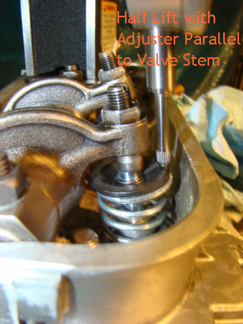
That's not anything like I did. I ran the shaft of the dial indicator parallel to the valve stem shaft so I could measure total lift of the valve. I then divided that number in half and used the adjustable pushrod to find a length that resulted in the adjuster screw being parallel with the valve stem at half lift. Changing the length of the pushrod would change lift some so it was a trial and error kind of thing. I also used shims under the rocker assembly to help with how much thread I had for moving the adjuster screws in the rocker arms. As I understand it the most important issue is lateral forces on the valve stems causing wear of the valve guides. Having the adjuster screw parallel with the valve stem at half open results in the least amount of wear. As I remember, it is better to give up a little lift to have the right orientation at half lift. Dave |
| DNHunt |
 Jul 8 2009, 12:10 PM Jul 8 2009, 12:10 PM
Post
#6
|
|
914 Wizard? No way. I got too much to learn.     Group: Members Posts: 4,099 Joined: 21-April 03 From: Gig Harbor, WA Member No.: 598 |
Here's a pic
Attached image(s) 
|
| McMark |
 Jul 8 2009, 12:19 PM Jul 8 2009, 12:19 PM
Post
#7
|
|
914 Freak!                Group: Retired Admin Posts: 20,179 Joined: 13-March 03 From: Grand Rapids, MI Member No.: 419 Region Association: None |
Half lift alignment will give your motor a longer life. You should check full lift to ensure that you are in the ballpark, but full lift should be sacrificed to ensure good half lift alignment.
|
| VaccaRabite |
 Jul 8 2009, 03:29 PM Jul 8 2009, 03:29 PM
Post
#8
|
|
En Garde!           Group: Admin Posts: 13,636 Joined: 15-December 03 From: Dallastown, PA Member No.: 1,435 Region Association: MidAtlantic Region 
|
Zach That's not anything like I did. Yeah it is. I just suck describing it properly. (IMG:style_emoticons/default/laugh.gif) What you described was what I remembered. What I had forgotten was the 1/2 lift step. I knew there was a step at 1/2 lift, but I could not remember what it was. As soon as I saw your picture, I remembered it - as I remember staring for about 30 minutes at my first valve a year ago trying to determine if it was perfect or not. As it is, it took longer getting those darned spiral keepers on that KB pistons use. So I am just now ready to start pushrod geo. Of course, at this point I have just enough time to get a shower and pick my son up from daycare. So, geometry will have to wait for Theo to go to bed for the night. Zach |
| charliew |
 Jul 8 2009, 04:57 PM Jul 8 2009, 04:57 PM
Post
#9
|
|
Advanced Member     Group: Members Posts: 2,363 Joined: 31-July 07 From: Crawford, TX. Member No.: 7,958 |
That is a good picture. I think the adjuster in that picture could be straighter or more inline with the valve stem. Also the rocker could be moved to it's left a little. The idea is to only have the adjuster working across as close to center as possible. If the adjuster is all the way up in the rocker arm the rocker arm needs to be raised to get the adjuster straighter. Close isn't really part of the procedure it needs to be right. Don't get in a hurry there is no rush it isn't easy but once it's right the guides will last a long time.
|
| Borderline |
 Jul 8 2009, 05:28 PM Jul 8 2009, 05:28 PM
Post
#10
|
|
Senior Member    Group: Members Posts: 720 Joined: 8-February 05 From: San Juan Bautista, CA Member No.: 3,577 Region Association: Northern California |
Your rocker arms need to be ground down about 1/16" where the swivel cup of the adjuster gets close. I found that if I turned the adjuster all the way in to where the swivel cup hit the arm and then backed it out about 2 turns was a good starting place. It needs some clearance to allow the swivel cup to swivel when it opens the valve. Also, if you really think about it, to get the adjuster screw inline with the valve at the half lift point, you need to add shims to the rocker arm shafts. My cam is pretty low lift and I needed to add about .080" of shims under the rocker arm mounting blocks. I my opinion, this is more important than the length of the push rod. The higher lift cams will need smaller shims if any at all.
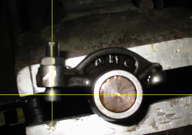
This photo shows the orientation of the rocker arm should be at half-lift. The valve stem should be exactly in line with adjuster screw at half lift. To get there, you have to adjust the pushrod length and the ht of the rocker arm shaft. IMHO Attached thumbnail(s) 
|
| bam914 |
 Jul 8 2009, 06:09 PM Jul 8 2009, 06:09 PM
Post
#11
|
|
Member   Group: Members Posts: 342 Joined: 23-November 03 From: Atlanta, Ga Member No.: 1,378 Region Association: None |
|
| VaccaRabite |
 Jul 8 2009, 06:50 PM Jul 8 2009, 06:50 PM
Post
#12
|
|
En Garde!           Group: Admin Posts: 13,636 Joined: 15-December 03 From: Dallastown, PA Member No.: 1,435 Region Association: MidAtlantic Region 
|
Either you or Travis sent it to me today via email when the forums were down. I have it printed... somewhere... but it is better to have it on hand then try to find it buried inthe garage. Zach |
| Jake Raby |
 Jul 8 2009, 08:13 PM Jul 8 2009, 08:13 PM
Post
#13
|
|
Engine Surgeon      Group: Members Posts: 9,398 Joined: 31-August 03 From: Lost Member No.: 1,095 Region Association: South East States |
My site isn't down and hasn't been to my knowledge..
Follow that article... I wrote it while doing the geometry process on one of my engines. |
| VaccaRabite |
 Jul 9 2009, 12:05 AM Jul 9 2009, 12:05 AM
Post
#14
|
|
En Garde!           Group: Admin Posts: 13,636 Joined: 15-December 03 From: Dallastown, PA Member No.: 1,435 Region Association: MidAtlantic Region 
|
My site isn't down and hasn't been to my knowledge.. Follow that article... I wrote it while doing the geometry process on one of my engines. It was down for about an hour or so when I had lunch. At least, I could not reach it then. My bookmarks work now, though. Got #3 and #4 done. #1 and #2 are prepped for the morning, after I do my class work. Zach |
  |
5 User(s) are reading this topic (5 Guests and 0 Anonymous Users)
0 Members:

|
Lo-Fi Version | Time is now: 15th January 2025 - 01:14 AM |
Invision Power Board
v9.1.4 © 2025 IPS, Inc.


