|
|

|
Porsche, and the Porsche crest are registered trademarks of Dr. Ing. h.c. F. Porsche AG.
This site is not affiliated with Porsche in any way. Its only purpose is to provide an online forum for car enthusiasts. All other trademarks are property of their respective owners. |
|
|
| Spoke |
 Apr 6 2008, 11:25 PM Apr 6 2008, 11:25 PM
Post
#1
|
|
Jerry      Group: Members Posts: 7,145 Joined: 29-October 04 From: Allentown, PA Member No.: 3,031 Region Association: None 
|
I'm prepping a 1.8L engine for the red 914 to replace the leaky 1.7L with one cylinder low on compression that's in the car. The installed engine has dual IDF40 Webers on it now.
When the PO bought the car, it had FI and was not running or was not running good. He took it to a local 356 shop and they pulled the FI and put on a single Weber just to get the car running. When the 356 shop moved locations, I received a box full of FI stuff from the car. My goal is to test each component and get the FI running again. I've tested most of the components including the distributor contact points, temp senders, throttle switch, and MPS. For the MPS, I just tested for vacuum leakage. It was leaking pretty badly so I took it apart and sealed it. I'll test it when I test the FI brain. I got a few questions that I'll get to in a few posts. First question is will it damage injectors if they are operated w/o fuel pressure? I plan to run the brain with injectors dry. Here's all the stuff I received: Attached image(s) 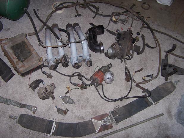
|
  |
Replies
| Spoke |
 Apr 7 2008, 12:00 AM Apr 7 2008, 12:00 AM
Post
#2
|
|
Jerry      Group: Members Posts: 7,145 Joined: 29-October 04 From: Allentown, PA Member No.: 3,031 Region Association: None 
|
Here's the brain with all its components connected. I want to run the brain with the distributor spinning with a drill. This is just to make sure the distributor works.
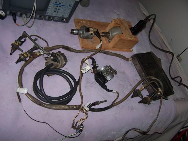 This is the "engine block". It was made from a small piece of 22ga steel. I put a series of cuts in one side and bent up every other tab to form several spades for electrical connectors. On the right is the CHT sending unit. 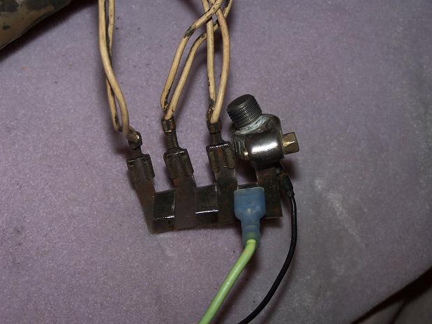 Here's the power connector for the brain. 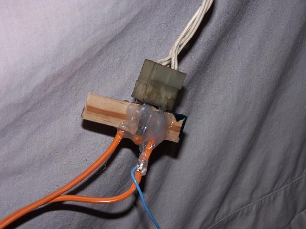 To test injectors and distributor functions, I made some extenders out of 0.016in brass. Again with a piece of wood and hot-melt glue, connectors were made. These allow easy measuring of signals. The one with 3 leads is for the distributor. 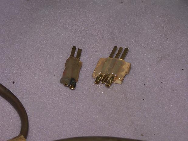 Here's a shot of the drill driving the distributor. This worked but the drill lacked the ability to remain at a certain speed and the drill caused annoying spiking on the scope. The drill + distributor has been replaced by an electronic circuit. 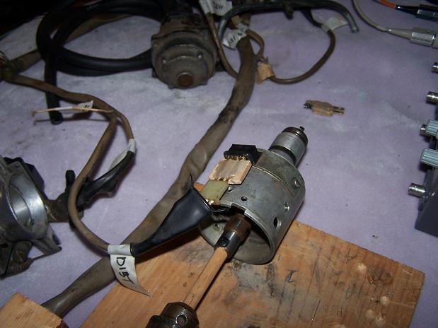 Here's injector #1 with an extender for measuring injector voltage. 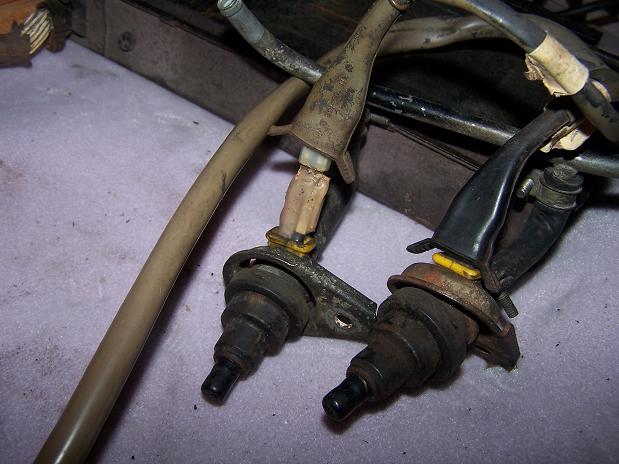 The CHT sender did not have a connector so I made one from brass and soldered the CHT sender to it. 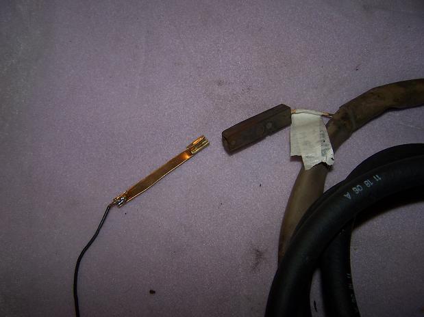 |
Posts in this topic
 Spoke Testing D-Jet FI Apr 6 2008, 11:25 PM
 Spoke To test the brain, I made a temporary harness to g... Apr 6 2008, 11:39 PM
 Spoke The drill+distributor worked well to show that the... Apr 7 2008, 12:19 AM
 Spoke Below are some scope traces of distributor contact... Apr 7 2008, 12:35 AM
 swl wow - creative stuff! keep it coming.
:popc... Apr 7 2008, 06:27 AM
 root Spoke,
I haven't scoped the injector voltage ... Apr 7 2008, 07:38 AM
 Bleyseng looks like its working but I would junk the inject... Apr 7 2008, 09:23 AM
 freezing14 thats a really great set up you have there , but I... Apr 7 2008, 06:31 PM
 Spoke Root,
Thanks for the info and link. Excellent rea... Apr 8 2008, 03:21 PM
 Spoke Now to test the throttle contacts.
I did the open... Apr 8 2008, 03:27 PM
 Spoke Still checking decel operation. With throttle clos... Apr 8 2008, 03:32 PM
 Spoke OK, now I don't know how to interpret this. My... Apr 8 2008, 03:44 PM
 r_towle two things.
Your TPS is out of adjustment, or its ... Apr 8 2008, 09:38 PM
  |
2 User(s) are reading this topic (2 Guests and 0 Anonymous Users)
0 Members:

|
Lo-Fi Version | Time is now: 3rd April 2025 - 01:31 PM |
Invision Power Board
v9.1.4 © 2025 IPS, Inc.


