|
|

|
Porsche, and the Porsche crest are registered trademarks of Dr. Ing. h.c. F. Porsche AG.
This site is not affiliated with Porsche in any way. Its only purpose is to provide an online forum for car enthusiasts. All other trademarks are property of their respective owners. |
|
|
| Spoke |
 Apr 6 2008, 11:25 PM Apr 6 2008, 11:25 PM
Post
#1
|
|
Jerry      Group: Members Posts: 7,145 Joined: 29-October 04 From: Allentown, PA Member No.: 3,031 Region Association: None 
|
I'm prepping a 1.8L engine for the red 914 to replace the leaky 1.7L with one cylinder low on compression that's in the car. The installed engine has dual IDF40 Webers on it now.
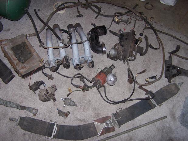
When the PO bought the car, it had FI and was not running or was not running good. He took it to a local 356 shop and they pulled the FI and put on a single Weber just to get the car running. When the 356 shop moved locations, I received a box full of FI stuff from the car. My goal is to test each component and get the FI running again. I've tested most of the components including the distributor contact points, temp senders, throttle switch, and MPS. For the MPS, I just tested for vacuum leakage. It was leaking pretty badly so I took it apart and sealed it. I'll test it when I test the FI brain. I got a few questions that I'll get to in a few posts. First question is will it damage injectors if they are operated w/o fuel pressure? I plan to run the brain with injectors dry. Here's all the stuff I received: Attached image(s) 
|
  |
Replies
| Spoke |
 Apr 7 2008, 12:19 AM Apr 7 2008, 12:19 AM
Post
#2
|
|
Jerry      Group: Members Posts: 7,145 Joined: 29-October 04 From: Allentown, PA Member No.: 3,031 Region Association: None 
|
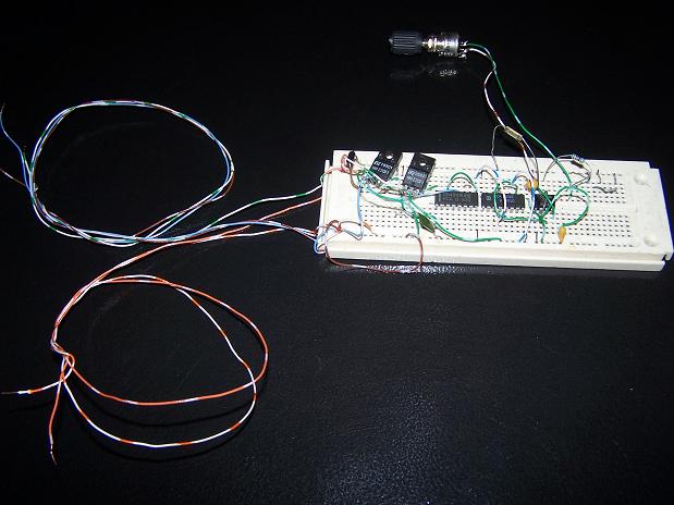
The drill+distributor worked well to show that the distributor contacts were ok but the drill is hard to set at a certain speed and also makes a lot of noise.
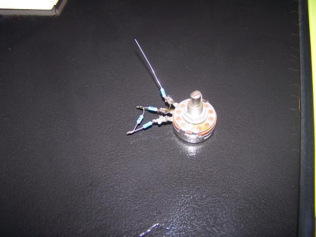
There are 2 contact points 180 degrees out of phase with each other and open and close once every single rotation of the distributor (2 rotations of the crankshaft) To simulate the 2 contact points of the spinning distributor, I use 2 FETs, one for each contact. To provide the speed, I use a 555 timer with potentiometer to vary the engine speed. The 555 is followed by a CD4040 ripple counter. The ripple counter slows down the frequency from the 555 (it was too fast) and also squares up the output. By choosing different outputs of the ripple counter, I am able to get the engine speed to vary from about 100RPM to over 5000RPM. The ripple counter is followed by a CD4049 hex inverter. One FET is driven by a single inverter and the other by 2 inverters to provide out of phase signals.  To simulate the CHT sender, I used a potentiometer to vary the resistance from 3500 ohms (engine cold) to 1000 ohm (engine hot). The resistor with lead pointing up is 1000 ohms so when pot set to 0 ohms, the CHT sender is 1000 ohms. The other 3 resistors in parallel with the pot lower the 5K ohm equivalent resistance to 2.5K ohms.  |
Posts in this topic
 Spoke Testing D-Jet FI Apr 6 2008, 11:25 PM
 Spoke To test the brain, I made a temporary harness to g... Apr 6 2008, 11:39 PM
 Spoke Here's the brain with all its components conne... Apr 7 2008, 12:00 AM
 Spoke Below are some scope traces of distributor contact... Apr 7 2008, 12:35 AM
 swl wow - creative stuff! keep it coming.
:popc... Apr 7 2008, 06:27 AM
 root Spoke,
I haven't scoped the injector voltage ... Apr 7 2008, 07:38 AM
 Bleyseng looks like its working but I would junk the inject... Apr 7 2008, 09:23 AM
 freezing14 thats a really great set up you have there , but I... Apr 7 2008, 06:31 PM
 Spoke Root,
Thanks for the info and link. Excellent rea... Apr 8 2008, 03:21 PM
 Spoke Now to test the throttle contacts.
I did the open... Apr 8 2008, 03:27 PM
 Spoke Still checking decel operation. With throttle clos... Apr 8 2008, 03:32 PM
 Spoke OK, now I don't know how to interpret this. My... Apr 8 2008, 03:44 PM
 r_towle two things.
Your TPS is out of adjustment, or its ... Apr 8 2008, 09:38 PM
  |
2 User(s) are reading this topic (2 Guests and 0 Anonymous Users)
0 Members:

|
Lo-Fi Version | Time is now: 3rd April 2025 - 01:31 PM |
Invision Power Board
v9.1.4 © 2025 IPS, Inc.


