|
|

|
Porsche, and the Porsche crest are registered trademarks of Dr. Ing. h.c. F. Porsche AG.
This site is not affiliated with Porsche in any way. Its only purpose is to provide an online forum for car enthusiasts. All other trademarks are property of their respective owners. |
|
|
| Larry.Hubby |
 Nov 2 2011, 09:55 PM Nov 2 2011, 09:55 PM
Post
#1
|
|
Member who doesn't post much, but has a long time in 914s   Group: Members Posts: 189 Joined: 24-November 04 From: Palo Alto, CA Member No.: 3,172 Region Association: Northern California |
Like many others on this board, I’ve lusted after the no-longer-made Getty-style door panels that mount the late (1974-89) 911 door pockets, armrests/lids, and handles to a 914 door. Faced with the fact that no one seems to be offering them anymore, I started looking at the possibility of making a set for myself. Like many 914 projects, however, this turned out to be much more complicated than I supposed. The photo below shows the final result, so I did get there. If you have the interest and the patience to read all the gory details of what I found it necessary to do to along the way, read on.
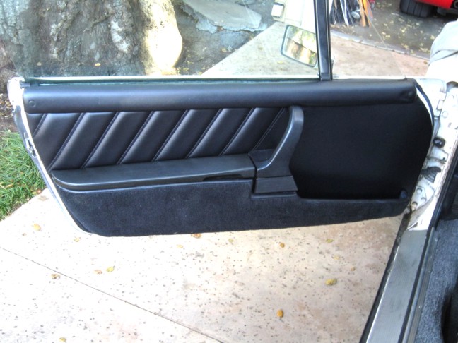 I decided the way to start was to acquire the 911 bits and pieces so I could see what fit and what had to be modified. A check on eBay revealed that the components are fairly cheap and easy to come by, being items that were made for many years and apparently aren’t in huge demand for replacement due to wear and tear on 911s. I was able to get the door handles and armrests/pocket lids for $10-15 each and a reasonable set of door pockets for $100. My vague general plan was to use 914 Appearance and Performance’s (www.914ap.com) fiberglass door panel cores, making whatever modifications proved to be necessary to mount the 911 components, and then have the panels upholstered in the “RS” style. Clearly, one of the difficult parts was going to be locating everything accurately if I started with completely blank door panels, so I asked James at 914ap if he would sell me cores with all of the holes for the mounting clips and the hangers that attach the panels at the top already accurately installed, and, kind soul that he is, he agreed to do so at no additional charge. Once all of these pieces arrived, I took my existing door panels off and trial fit the components to see what kind of trouble I was in, having by now already spent over $200 with no guarantee that I wouldn’t run into some very difficult problem that would make me give up on the whole idea. The photo below shows this first look. 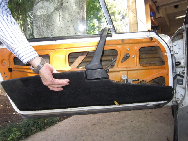 The good news is that the 911 and 914 doors are apparently almost exactly the same length, front to rear, and the rear edges of the two doors slope back at almost the same angle, since the door pockets are a close fit to the 914 door contours. The height of the door pockets is also essentially the same as that of the 914 driver’s door pocket, and the pull mechanism in the 911 handles falls at a height that intersects almost perfectly the path of the door pull rod of the 914, suggesting that it may be easy to hook up the two to operate the door. The bad news, however, is that the 911 doors are apparently considerably taller than the 914 ones, the upper mounting points of the 911 door handles standing some 2 ¾” higher than the surface they would need to mount to on the 914 door. This means that either the handles or the door pockets have to be shortened by this amount to fit. Shortening the door pockets would be difficult, not to mention the facts that it would seriously reduce the pocket capacity and almost eliminate the front section of the pockets, miss-align the handle pull and the door operating rod, and place the rear pocket lid rather low to serve as a comfortable armrest. Looking again at the few pictures I have of actual Getty panels, it’s clear that they too chose to shorten the handles rather than the pockets, so that seemed like the right approach. To shorten the handles, I chose to re-bend them to the correct shape, cut off the excess length, and then cut off the mounting bracket from the original end of the handle and re-attach it to the shortened handle’s end. The handles have a metal strap “skeleton”, around which firm cushioning foam and a vinyl outer covering is molded. Where the strap emerges from the foam and vinyl at the upper end of the handle and is bent up at 90 degrees to be riveted to the mounting bracket, you can see that it’s a flat piece of metal about 2mm thick and 15mm wide. I had thought to cut off the bracket by cutting the strap about ½” before the bend, carefully trim back the foam and vinyl from the end of the shortened handle on the top and bottom only with a carpet knife to expose a similar amount of the strap, overlap the exposed part with the ½” section attached to the bracket, and spot weld the two together. By keeping the amount of the vinyl trimmed from the handle to a minimum, I hoped to hide the joint entirely with the window sill trim piece that has to be added to the top edge of the panel anyway to hide the upper attachment of the handle. To re-bend the handles, I made a simple bending jig. I set my digital camera to full telephoto to get the flattest perspective possible, and then photographed one of the original handles directly from the front. I then imported the picture into a drawing program (Corel Draw in my case) and scaled it so that I could measure actual dimensions on the image. I then used a Photoshop-like bitmap editing program (Corel’s is called Photo-Paint) to duplicate the top portion of the image that contains the upper end of the handle, move it down 2 ¾”, and match it up with the lower part of the handle. This gave me a retouched image of the shortened handle I wanted to end up with. I printed this image out full-size and then cut out the shape of the space under the handle to use as a template for the curve of the shortened handle. 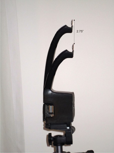 Using the template, I marked the shape on the end of a 6” thick stack of glued-together MDF (Medium-Density Fiberboard) pieces (8, ¾” thick pieces), and band-sawed out the shape. Attaching the flat side of this shape to a 6”x6” piece of MDF, and adding four ¼”-20 “T”-nuts in appropriate locations produced the bending jig shown below. The next photo shows one of the handles secured to it, ready for bending, and the third shows the result of the bending operation. 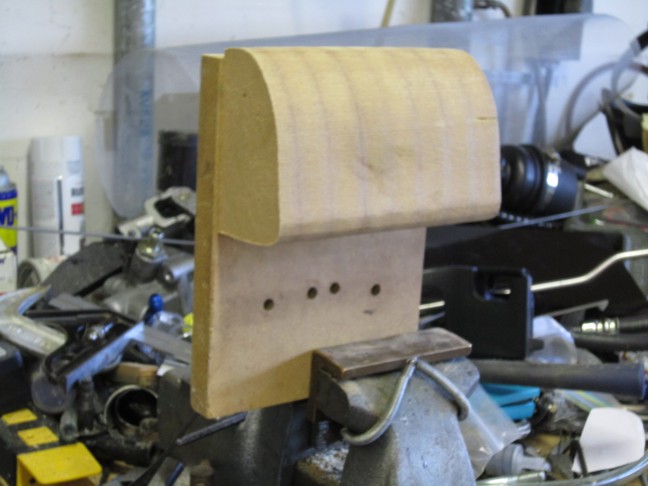 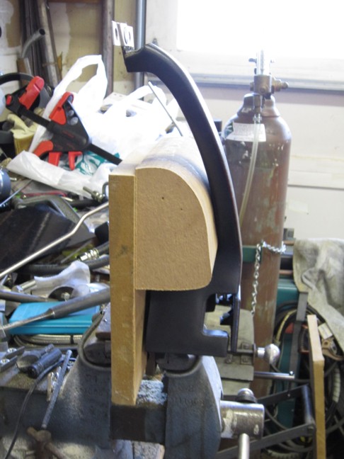 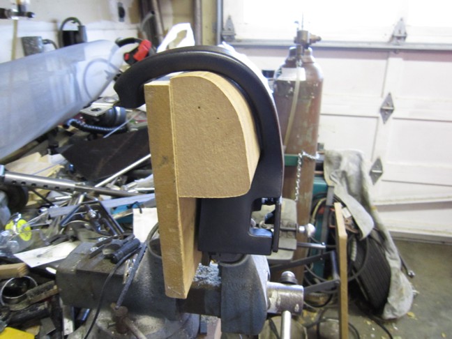 I had to modify the shape of the jig to compensate for the tendency of the handle to spring back slightly after bending. This done, the two handles bent easily. I also used the jig to hold the handles while cutting off the excess length after bending. After making the first of these cuts, however, I got another surprise. The metal strap inside the handle isn’t flat like it is when it emerges from the foam at the top to attach to the bracket, it’s formed into a cupped cross-section, presumably to add stiffness that helps hold the curved shape of the handle. 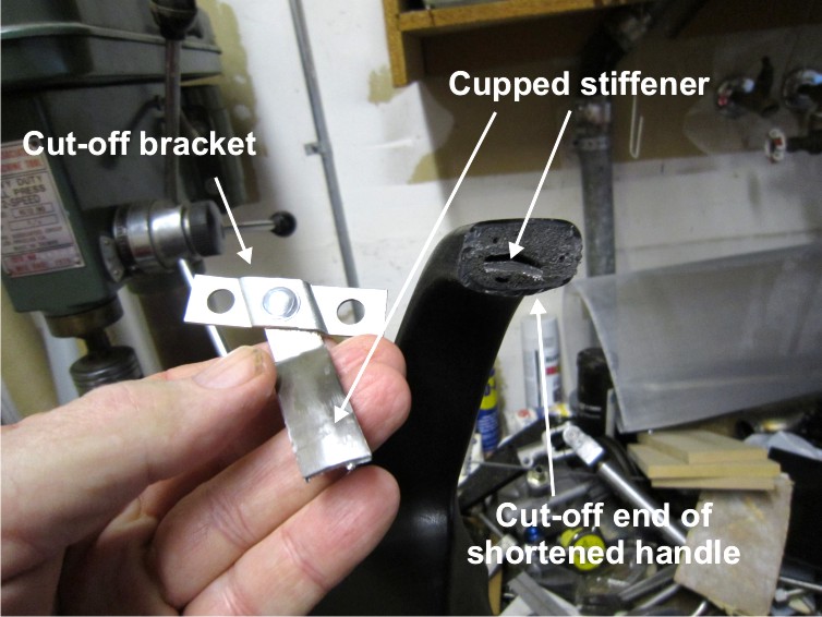 This meant that my overlapping and spot-welding scheme for re-attaching the bracket end wasn’t going to work. After considering several different schemes, I finally decided to produce a similarly-cupped, rather than flat, end on the bracket, then overlap this end with, and attach it to, the end of the strap in the shortened handle, as I had planned to before. To do this, I cut a ½” length of the cupped strap from the excess length of the handle that I had cut off, cut off the straight part of the strap that attaches to the top mounting bracket right at the bend rather than ½” back from it, and welded the former to the latter in the correct alignment. Considerable flex in the handle fortunately makes the alignment required not very critical. This was kind of a delicate welding job, but I managed to do it with my TIG setup using a 1/16” electrode and the lowest current setting at which the arc was stable. It should be easier to do with a MIG setup. 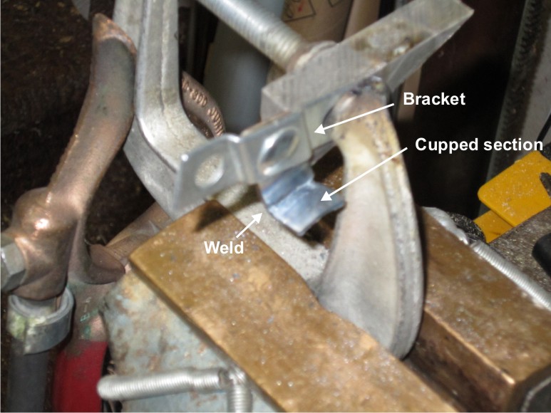 This allowed the parts to overlap inside the handle, as originally intended: 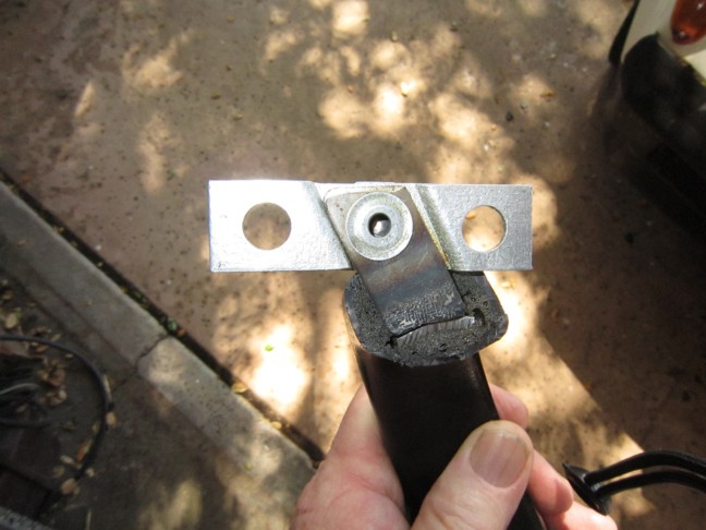 I also decided that spot-welding would require removing so much of the vinyl and foam that it would be difficult to conceal later, and elected to attach the two pieces with screws instead, since this could be done by removing as little as ¼” of the vinyl and foam from the top inside only, as shown below. 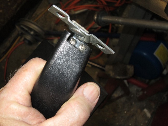 Once the cupped sections were attached to the brackets, I drilled through each one with a #28 (#6-32 tap size) drill on either side, overlapped them and the ends of the straps inside the ends of the handle with the former on top, and used one of the holes as a guide to drill through the strap end with the same #28 dill, taking care to not drill all the way through the foam and vinyl on the bottom. I then removed the brackets and enlarged the holes in them with a #19 (#6 screw clearance size) drill, re-inserted the brackets, and used them as guides to tap the holes in the ends of the straps below them with a #6-32 tap. I drilled and tapped one hole in each handle at a time like this in order to be able to install the first screw to hold the two parts in alignment while I drilled and tapped the second holes in the straps. Once both holes were tapped in each handle, I installed the screws with Loctite red. The completed shortened handles came out looking like this: 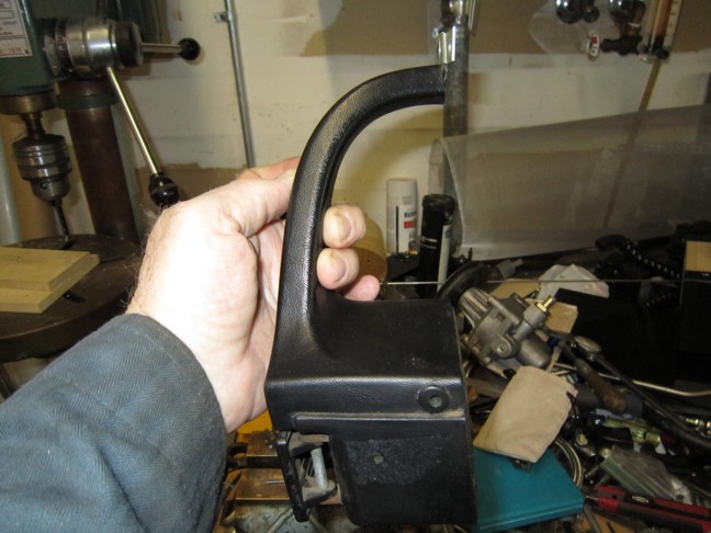 And, compared to an original 911 handle, like this: 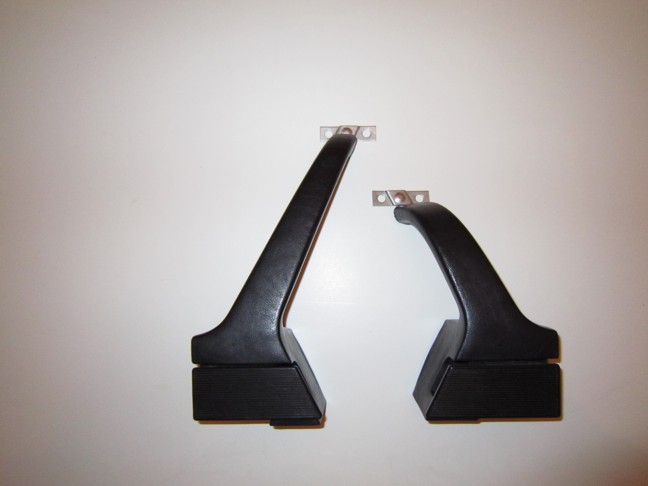 Having shortened the handles, I could then locate all the attachment points for the various components. I installed clips in two of the pre-drilled holes in the door panel cores, and engaged the hangers at the top as well as the two clips in their respective holes to locate the panel. I then clamped the door pockets in place and used their mounting holes as a guide to drill holes for #8 self-tapping screws through both the panel cores and the inner surface of the door. I used #8 hardware because it’s virtually the same size as the 4mm screws Porsche used in the same locations, and I could get nice-looking black-finish screws and finishing washers from McMaster-Carr (www.mcmaster.com) in this size, but not in the more correct 4mm size. I found that one of the mounting holes for the 911 pockets fell right on top of one of the panel mounting clips on the 914, so I located this screw 1” to the rear compared to its nominal location and drilled this hole through the pockets as well as the two other layers. Once all these holes were drilled, I enlarged the holes in the panel cores (and the one in the pockets) to clearance-size, and then installed the screws temporarily to locate the pockets. The handles then fastened to the pockets with a single screw, which located them well-enough to allow me to mark the locations for each handle’s two lower 6mm mounting bolts and the clearance hole for the pull device, be it rod or cable, that transfers the pull of the lever that your hand operates to the door operating rod, and the area of the panel cores that needs to be cut out to clear the handles’ upper mounting brackets. 914ap’s door panel cores are fiberglass and have the rounded area that becomes the window sill after upholstery molded in rather than formed in metal as part of the hanger strip, so this is easy to do. After marking, I removed the handles, pockets, and panel cores and drilled and cut out the marked holes in the cores, then re-assembled them all and marked the two top handle mounting bolt locations. The top mounting bolts go into an easily-accessible location on the door, but the lower two bolts fall on top of the channel pressed into the door to clear the door operating rod. 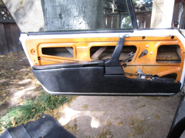 To provide solid attachment points for these bolts, as well as for whatever mechanism I decided to use for turning the door handle pull to attach it to the 914 door rod, I elected to mount ~5”x5” sheet metal plates over the channels covering the locations of the bottoms of the 911 handles. I attached these plates with screws and spacers that hold their outer surfaces at the same distance above the door sheet metal as the stock plastic spacer holds the door panel at the driver’s door pocket top right-hand mounting screw. After removing everything to mount these plates, I re-installed the panel cores and marked the hole locations for the lower handle mounting bolts and the clearance holes on the plates, then removed it all yet again and drilled the holes in the plates. I also got some 6mm x 1.0mm PEM-style press-in captive nuts for thin (1mm) sheet metal from McMaster-Carr, and used these for the handle mounting bolt anchor points on both the door and the plates. I found, however, that the nuts don’t grip very well on the thin door sheet metal, which is about 1mm thick, and tended to be easy to push out when trying to start the mounting bolts. I wound up replacing the ones in the door metal for the upper bolts with ¼”-20 rivet nuts, which swage into place and are very secure once installed. If I did it over, I’d use these for all four bolts on each door, so that I wouldn’t have the potentially confusing mix of metric and English bolts that I have now. Oh well, live and learn. Once the handles are located, the combination of them and the pockets locates the armrests/lids, which just require two through mounting holes in the panel cores to mount the rear hinge anchor block, but also may require aligned holes in the door to clear the nuts on the back side of the panels. With all of the components now mounted, I was ready to hook up the new door handles to operate the doors. I had no information on how Getty hooked up the door handles, or what they did about operating the locks. The 911 latch mechanism is quite different from that in the 914, having two separate mechanical inputs for the operation of the latch and the lock. The 914 latch derives both functions from the pushing or pulling of a single rod. Pushing the rod (toward the latch) about 10mm from the unlocked position locks the car, while pulling it 10mm from the unlocked position activates the latch and opens the door. The two functions are separated by a complex door handle mechanism that has two operating levers, one for the lock that can push or pull only the 10mm needed to lock/unlock the door, but also locks the other, door opening lever from moving when the door is locked. The 911 door handles have no such mechanism, because the lock/unlock function on the 911 is operated by a separate rod that is moved by either a rotary knob recessed into the door panel, or a cylindrical knob that protrudes vertically from the inside window sill at the rear near the latch, similar to the arrangement used on many American cars. The Getty panel photos I have show no secondary knobs that might be presumed to operate the lock, so I assume everything was done with the single lever of the 911 handle. If that is true, one has basically two options: 1. Give up the ability to lock/unlock the doors from inside the car. Do that only from outside with the key. 2. Use electric door locks. In either case, the door handle lever could be hooked up to first unlock, if locked, and then open, the door, or just to open the door if unlocked, depending upon the amount of pull the handle is arranged to apply. In my case, I was planning on using electric locks, so I could manually lock and unlock the doors from the inside with a switch as long as the electrical system does not fail. But, because I would want to always be able to open the doors from the inside, even if the electrical system failed with the doors closed and locked, and I didn’t want to make arrangements for a secondary knob or handle to operate the lock, I chose to make the handle pull the door rod enough to both unlock and open the door. The elaborate mechanisms designed to allow locking the door so that it cannot be opened from the inside by operating only the normal lever are mostly to guard against small children accidentally opening a door while the car is moving…a valid concern in a family sedan, but not such a worry for my 914. I suppose another alternative would be to leave the stock 914 door handle functional, and use the 911 handle only as a grip, securing its operating lever somehow so it doesn’t flap open. This would simplify things substantially, but would result in a much less clean installation in my opinion. Unfortunately, however, there are further miseries associated with the door opening mechanism. One is that the stock 914 door handle also supports the lower end of the door operating rod, and, if it is removed, some sort of other support that constrains the rod to move only in a push-pull fashion and not flop around must be provided. Another is that the stroke that the 911 handle is designed to pull is much longer than that necessary to operate the 914 latch, even with the double travel to unlock the door as well as open it. With a lever that your hand operates of roughly the same length on both the 914 and the 911 handles, the 914 handle pulls the door rod with a lever arm only .6” long, while the corresponding dimension for the 911 handle is 1.57”. This unfortunately means that, if the 911 lever is hooked up directly to the 914 door rod, a nearly 3x harder pull than normal will be necessary to operate the latch. Having done this initially, I can testify that the force required seems so high that you tend to be worried about breaking the plastic 911 lever. Some means of increasing the lever advantage of the 911 handle is required, as is a way to change the direction of pull by 90 degrees to align it with the door rod of the 914. There are several ways to do this, but, in my case, in order to get enough travel to pull the door rod 20mm, to support and constrain the rod as described above, to avoid having any part of the mechanism protrude into the interior of the door, and to not change the attachment point very much for the electric door lock actuators, which were already installed on my car, the best solution seemed to be to mount a remote lever that moves in a vertical plane in the door channel and operate it from the 911 handle via a small diameter wire cable, turning the motion of the cable with a small pulley at the handle mounting plate. The photos below show this arrangement, as I built it. 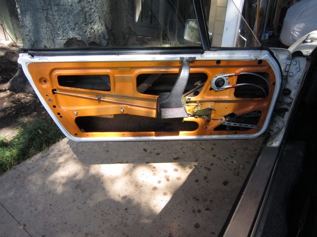 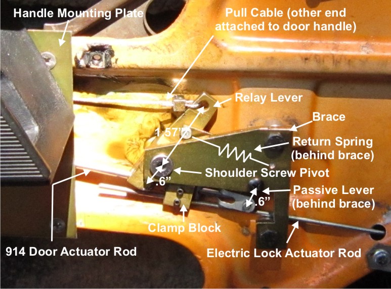 The cable pulls on one end of the lever 1.57” from its pivot point, and the other end of the lever is .6” long and bears against a rectangular clamp block that is set-screwed to both the door rod and to the rod from the electric lock actuator. To form the pivot for this lever, I used a 6mm shoulder screw, anchoring it to a 6mm captive nut in the door sheet metal, and supporting its head with a flat metal brace that attaches to the stock door handle attachment points. This support for the outer end of the pivot bolt prevents the pulling force from causing a torque that would likely rip the captive nut out of its mounting hole. The brace also supports a small .6” long passive lever that just holds up the lower end of the door rod, and a spring that holds the 911 lever closed when the door is unlocked by pulling on the relay lever. The passive lever locates the rod in the up and down direction, while the relay lever locates it in the direction perpendicular to the plane of the door. Because the passive lever that engages the lower end of the door rod is now vertical (the lever on the stock door handle that performed the same function was horizontal), the door rod needs to be re-bent so that the right angle bend that engages the lever is horizontal rather than vertical. Fortunately, I was able to locate the passive lever enough further to the rear that there is room to re-bend the stock rod. If you think that all of this is ridiculously complex, you’re not alone. Perhaps someone will come up with a simpler way to accomplish the same thing. I can assure you, however, that all of the constraints I mentioned are necessary in some form if you want the door release to work as you expect. What it illustrates, I suppose, is what a well-designed and functionally elegant mechanism the stock door handle is. For the cable to tie the 911 handle to the relay lever inside the door, I used stainless steel 3/64” 7x19 strand core wire rope, which I got, once again, from McMaster-Carr. To anchor the ends, I made some small clamp blocks from ¼” square steel rod, with two parallel 1/16” diameter thru holes and #4-40 threaded holes intersecting each bore from the side. The cable passes through one hole, loops through whatever it’s supposed to attach to, and then back through the second hole. A #4-40 set screw clamps the cable in each bore to stabilize the size and location of the loop. A simple hole in the long end of the relay lever accepts one end of the cable. I made an end fitting for the other end that allows it to snap into the stock 911 plastic clip by mitering two pieces of 4mm diameter steel rod and welding them together at 90 degrees to form a nice sharp right angle, then trimming both ends to length and welding one of them to a small washer to provide a hole for the cable to loop through. The only other piece of hardware required for the release mechanism was some sort of pulley to turn the direction of the cable pull through 90 degrees. To accomplish this, I made some end fittings out of ½” x ½” aluminum angle that hold a short piece of 3/16” steel rod as an axel and mount with screws to the handle mounting plate. For the pulley, I cut a ½” length of thread from a 5/8” coarse-threaded bolt, used a lathe to drill a 3/8” hole through the center, and snapped in some 3/8” OD x 3/16” ID flanged bushings to allow it to fit onto the axel and turn like a pulley. I used a bolt of this size because I found that the threads were the perfect width and depth to contain the 3/64” cable without it protruding above the threads, and so there would be multiple grooves to contain the cable, both so that it would not be difficult to engage the cable in a groove, and so that I could wrap the cable around the pulley more than 360 degrees, if desired. The bolt was cheap, readily-available, and saved me having to machine a groove that matched the cable. Once I got all the pieces made, I put it all together without worrying about the upholstery and used it for a week or so to verify that it worked and was likely to keep working for a while. I then disassembled it all and had all the steel parts plated with yellow zinc for corrosion resistance. On “final” assembly, I used all stainless hardware for the parts that are under the plastic vapor barrier. The only things left to deal with before taking the car to the upholstery shop were the trim pieces that had to be made to cover the inside window sill area and hide the top mounting bolts for the 911 door handles and their mounting brackets. I looked at several different ways to make these, and finally settled on bent sheet metal parts made of thin (.040”) steel and attached to the fiberglass panel cores with #8 self-tapping screws that reach through holes drilled into the fiberglass and thread into clip-on speed nuts held by small aluminum pieces pop-riveted to the underside of the door panels. One screw at the very front, and one at the very rear hold them on. Shown below is the drawing I made mine from, and a detail of the riveted aluminum pieces that hold the speed nuts. 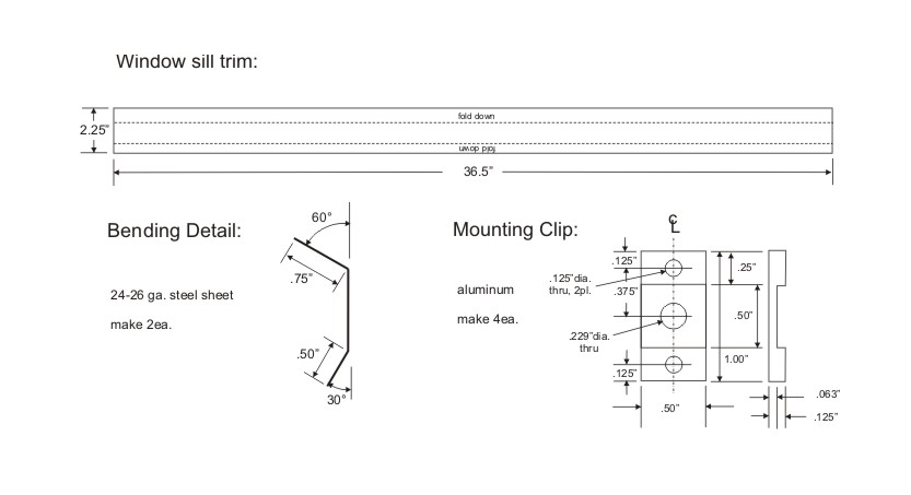 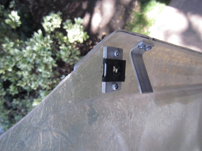 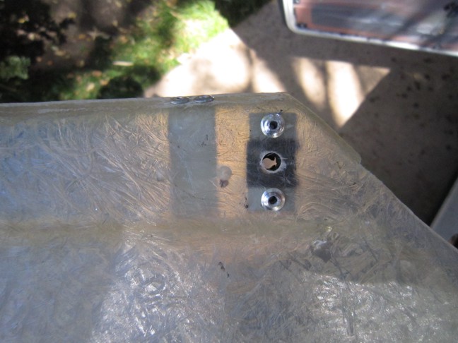 Not shown on the drawing is the fact that the sheet metal parts need to be notched to clear the front window channel on top and the handle’s metal strap that attaches to its top mounting bracket on the bottom. Also not shown is the finishing for the ends that I used, which amounted to making a ~1/4” long cut with tin snips in the direction of the length along each bend line, bending the resulting tabs on the end of each section down at ~45 degrees, spot-welding the overlapped areas together, and then trimming the tabs to form a slight curved enclosure for the rear end. At the front end, the shape required is different, but the forming principle is the same. Below are photos of the clearance notches and the finished ends on my trim pieces before upholstery. The notches: 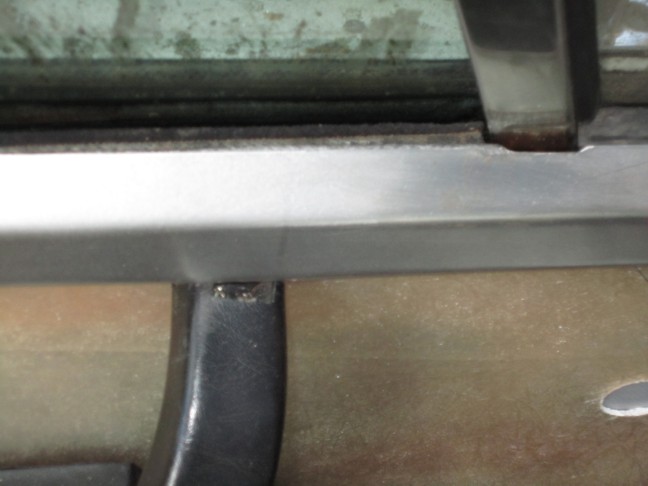 Rear end: 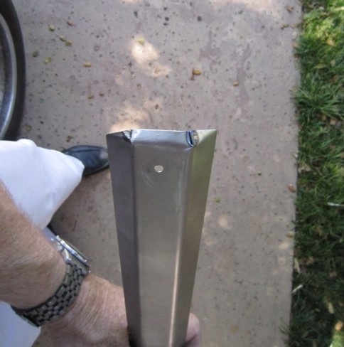 Front end: 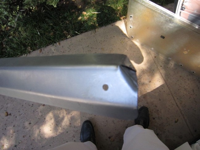 Ready for upholstery: 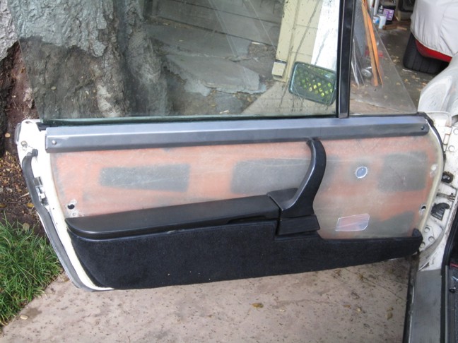 I took the car with the functionally complete door panels in place to Palo Alto Upholstery, 2023 E Bayshore Rd. East Palo Alto. They did a beautiful job replicating the factory 911 “RS” look for me. They finished the sill trims by gluing a thickness of firm foam sufficient to hide the cuts into the top of the handles onto the outside of them, and then covering them with vinyl. They handled providing access to the mounting screws, which have to be removed to get at the handle upper mounting bolts when the door panel is removed, by coring holes in the foam and gluing short sections of 8mm ID plastic tubing in them over the mounting holes before the vinyl was applied. After they glued on the vinyl, they cut out the vinyl over the inside of these little tubes, allowing access through to the mounting screws, and then plugged them with factory trim plugs. 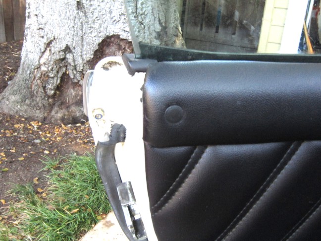 As you can see from the photo below of the finished result, I went with power windows as well. But that’s another story. 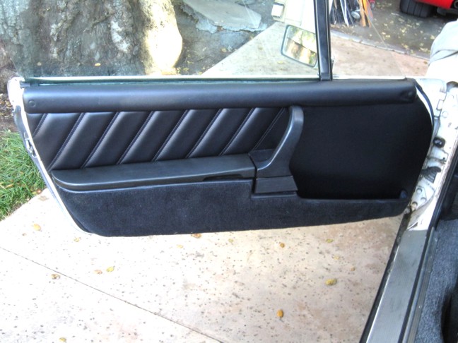 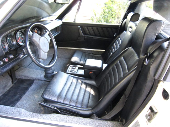 |
  |
Replies
| TravisNeff |
 Nov 3 2011, 01:54 PM Nov 3 2011, 01:54 PM
Post
#2
|
|
914 Guru      Group: Members Posts: 5,082 Joined: 20-March 03 From: Mesa, AZ Member No.: 447 Region Association: Southwest Region 
|
Nice work, and thanks for the writeup and pics!!
|
Posts in this topic
 Larry Hubby Getty-style door panels Nov 2 2011, 09:55 PM
 kg6dxn Very Nicw! Nov 2 2011, 11:01 PM
 nsr-jamie Excellent !! Nov 3 2011, 12:00 AM
 morph very nice i have most of those pieces. but i didnt... Nov 3 2011, 12:04 AM
 SirAndy :thumbsup:
That looks much better than i thought ... Nov 3 2011, 12:06 AM
 TurboWalt Great job, anyone willing to make me a pair? Nov 3 2011, 01:01 AM
 ewdysar Very Impressive! :trophy:
If anyone want... Nov 3 2011, 01:16 AM

 bcheney Wow...this is very cool how to guide! Great wo... Nov 3 2011, 05:00 AM
 jmill You might not post much, but when you do it's ... Nov 3 2011, 07:26 AM

 jaxdream
You might not post much, but when you do it's... Nov 3 2011, 07:47 AM

 mikea100
I vote Classic.
:agree:
Awesome. :trophy: Nov 3 2011, 07:48 AM

 zymurgist
I vote Classic.
:agree: :trophy: Nov 3 2011, 08:10 AM


 Philip W.
I vote Classic.
:agree: :trophy:
:agree:... Nov 3 2011, 12:16 PM

 BIGKAT_83
You might not post much, but when you do it's... Nov 3 2011, 12:18 PM
 Andyrew Very nice work! Nov 3 2011, 08:12 AM
 SirAndy Classic it is ... :D Nov 3 2011, 12:18 PM
 Philip W. I just found a 911 complete door panel and pocket ... Nov 3 2011, 01:44 PM
 treborzerimar Classic, please! Nov 3 2011, 02:38 PM
 racerbvd [color=#FF0000]Classic :beer2:
I should have a... Nov 3 2011, 03:37 PM
 Larry Hubby Thanks guys. I still wonder how Getty handled the... Nov 3 2011, 07:01 PM

 racerbvd
Thanks guys. I still wonder how Getty handled th... Nov 3 2011, 07:21 PM
 Eric_Shea Holy $hit... great fab work Larry. :trophy: Nov 26 2011, 09:00 PM
 partwerks Those look nice, but I don't want to get into ... Nov 26 2011, 10:40 PM
 computers4kids Unbelievable! I would never have had the pati... Nov 27 2011, 07:49 AM
 majkos very nice write up.
Thanks for taking the time to ... Nov 27 2011, 09:35 AM
 Dr Evil I have a set of handles waiting to do this on my c... Nov 27 2011, 11:06 PM
 gothspeed Fantastic thread, back from the dead ......... :D... Mar 21 2012, 06:43 PM
 hammergtv That's impressive excellent job, Mar 17 2016, 02:29 AM
 boxsterfan OMG! That is awesome. If you make more, pleas... Mar 17 2016, 09:29 AM
  |
1 User(s) are reading this topic (1 Guests and 0 Anonymous Users)
0 Members:

|
Lo-Fi Version | Time is now: 23rd December 2025 - 04:56 PM |
Invision Power Board
v9.1.4 © 2025 IPS, Inc.


