|
|
|
Porsche, and the Porsche crest are registered trademarks of Dr. Ing. h.c. F. Porsche AG.
This site is not affiliated with Porsche in any way. Its only purpose is to provide an online forum for car enthusiasts. All other trademarks are property of their respective owners. |
|
|


| dlo914 |
 Nov 30 2012, 12:45 AM Nov 30 2012, 12:45 AM
Post
#1
|
|
Whatchu' lookin' at?!?!  Group: Members Posts: 3,432 Joined: 6-September 04 From: San Gabriel, CA Member No.: 2,697 |
So i've retrofitted some LED rings into my daily driver, but i'm only using the LEDs as the running lights and using the filament bulb when brakes are applied. how would i go about using the LEDs for both running and braking light usage? i know i'm suppose to add a resistor to each positive LED wire, but i'm so confused as to what OHM rating or % etc i'm suppose to use. The guys at two radioshacks were useless.
Here's how they look at the moment: (IMG:http://www.914world.com/bbs2/uploads_offsite/i62.photobucket.com-2697-1354257938.1.jpg) |
   |

 
|
  |
Replies
| Tom |
Nov 30 2012, 02:24 PM
Post
#2
|
|
Advanced Member Group: Members Posts: 2,139 Joined: 21-August 05 From: Port Orchard, WA 98367 Member No.: 4,626 Region Association: None |
Here is a simple led circuit than will allow the running light LED's to be one brilliance and the brake lights to be a higher brilliance. Your ring LED's will be hard to modify to do this.
Say each LED was a .2 watt. With (it looks like over a hundred LED's) that would require a 25 watt or bigger resistor. ( current thru one section of the circuit is constant thru the whole circuit.) Resistors this size will not be cheap. Smaller ones for pennys. Also if this is a plug in module, it will be difficult to modify to have the brake light circuit in parallel as in the simple drawing. You would also have to have terminals on the headlight switch to allow rewiring to make the brake light circuit the same brilliance reguardless if the headlights are on or not. Here is how the circuit works: When headlights(running lights) are on, the path is from batt + to closed contacts of the headlight switch, thru R1, to LED's to ground. If brakes are applied, you will have a parallel circuit with R2 also connected to the LED's. Resistors in parallel are less ohmic value than either resistor. Hense the brake lights and running lights would get brighter. With no headlights on, ( the doted line is hooked up) the path is a parallel one from batt + thru brake light switch to headlight switch thru parallel resistors to LED's to ground. The headlight running light LED's and brake light LED's would operate. hope this has shed some light ( no pun intended) on your delima. I don't know how auto lights are dimmed using LED's, but I suspect it is a cycle of on/off pulses to the LED's as they are very fast in operation. Say running lights get a pulse rate of 60 and brake lights. seperately wired, would have a pulse rate of 100. Brake lights would be brighter. Tom Attached thumbnail(s) 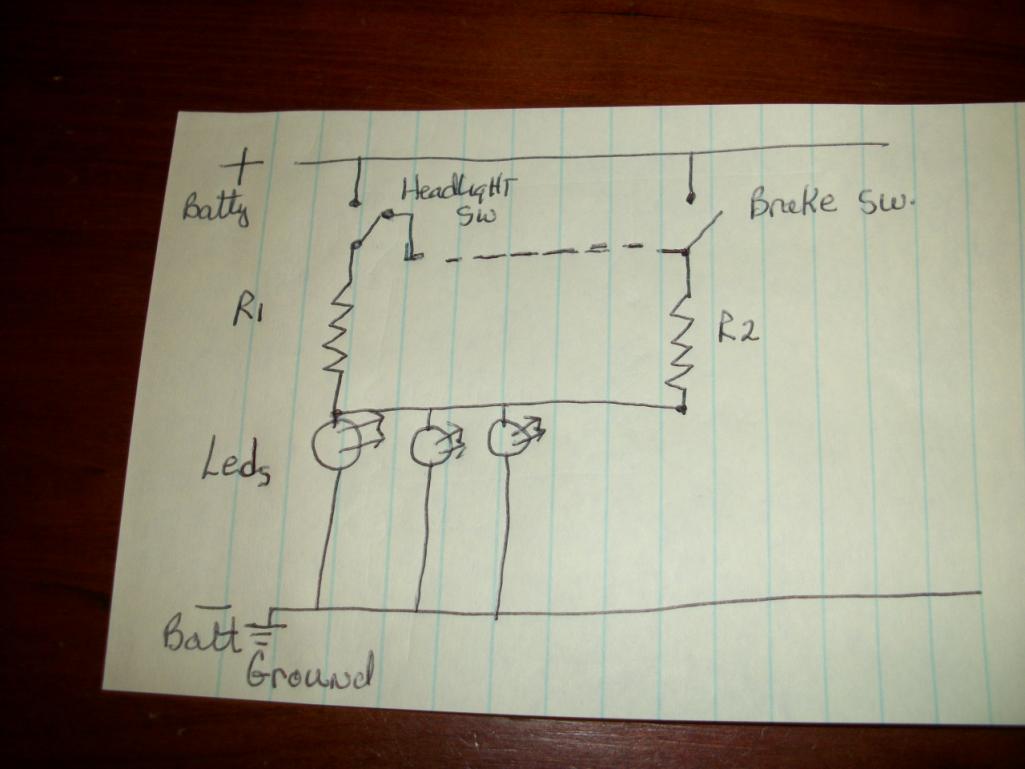
|
|
|
|
Posts in this topic
 dlo914 SOT: electrical gurus check in... Nov 30 2012, 12:45 AM
 Tom LED brilliance is controlled by current flow. Curr... Nov 30 2012, 04:49 AM Tom Are these rings a plug in to the regular socket wh... Nov 30 2012, 05:58 AM Spoke For the brake light with higher intensity, as Tom ... Nov 30 2012, 08:26 AM Bartlett 914 I am doubtful that adding resistance will give sat... Nov 30 2012, 08:33 AM Nine_14 http://en.wikipedia.org/wiki/LED Nov 30 2012, 09:12 AM mr914 Temporary, or could be permanent...
Buy a variabl... Nov 30 2012, 03:04 PM Dave_Darling All the automotive LED taillights I know of blink.... Nov 30 2012, 05:23 PM
Tom LED brilliance is controlled by current flow. Curr... Nov 30 2012, 04:49 AM Tom Are these rings a plug in to the regular socket wh... Nov 30 2012, 05:58 AM Spoke For the brake light with higher intensity, as Tom ... Nov 30 2012, 08:26 AM Bartlett 914 I am doubtful that adding resistance will give sat... Nov 30 2012, 08:33 AM Nine_14 http://en.wikipedia.org/wiki/LED Nov 30 2012, 09:12 AM mr914 Temporary, or could be permanent...
Buy a variabl... Nov 30 2012, 03:04 PM Dave_Darling All the automotive LED taillights I know of blink.... Nov 30 2012, 05:23 PM
 Spoke
If it were as simple as putting a resistor in lin... Nov 30 2012, 05:52 PM Spoke Here's a switching converter to efficiently dr... Nov 30 2012, 06:07 PM stugray There are off the shelf drivers that can do this.
... Nov 30 2012, 07:34 PM Spoke
There are off the shelf drivers that can do this.... Nov 30 2012, 07:51 PM nukepipe
So i've retrofitted some LED rings into my da... Nov 30 2012, 08:42 PM aircooledtechguy I'm probably missing something here, but if yo... Dec 1 2012, 12:09 AM falconfp2001 I would say you need to check this site out
http:... Dec 1 2012, 02:58 AM bperry Here is a link to a DIY article on how to wire up ... Dec 1 2012, 12:29 PM
Spoke
If it were as simple as putting a resistor in lin... Nov 30 2012, 05:52 PM Spoke Here's a switching converter to efficiently dr... Nov 30 2012, 06:07 PM stugray There are off the shelf drivers that can do this.
... Nov 30 2012, 07:34 PM Spoke
There are off the shelf drivers that can do this.... Nov 30 2012, 07:51 PM nukepipe
So i've retrofitted some LED rings into my da... Nov 30 2012, 08:42 PM aircooledtechguy I'm probably missing something here, but if yo... Dec 1 2012, 12:09 AM falconfp2001 I would say you need to check this site out
http:... Dec 1 2012, 02:58 AM bperry Here is a link to a DIY article on how to wire up ... Dec 1 2012, 12:29 PM |
1 User(s) are reading this topic (1 Guests and 0 Anonymous Users)
0 Members:

|
Lo-Fi Version | Time is now: 25th June 2024 - 09:04 PM |
Invision Power Board
v9.1.4 © 2024 IPS, Inc.