|
|

|
Porsche, and the Porsche crest are registered trademarks of Dr. Ing. h.c. F. Porsche AG.
This site is not affiliated with Porsche in any way. Its only purpose is to provide an online forum for car enthusiasts. All other trademarks are property of their respective owners. |
|
|
| 904svo |
 Dec 3 2012, 11:21 AM Dec 3 2012, 11:21 AM
Post
#1
|
|
904SVO    Group: Members Posts: 1,124 Joined: 17-November 05 From: Woodstock,Georgia Member No.: 5,146 |
Here are some of the fixes I used when installing a 2007 Subaru WRX engine in my car.
I did not want to change any of the wiring in my car as it has a 1973 914 wiring harness installed in it. I wanted to keep the stock gauge cluster in it but adapt it to a Subaru engine to look stock. Here are some of the troubles I found and the fixes I used #1 Tach Convert the 5 volt output signal from the Subaru to a high voltage pulse that the 914 tach requires. 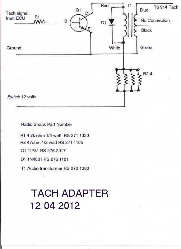 #2 Starter circuit Added a hot starter relay which removed all the Subaru starter check circuits 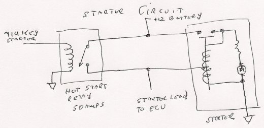 #3 Stop Fuel level DTC’s Note if connected to 914 low warning , this will reduce power level 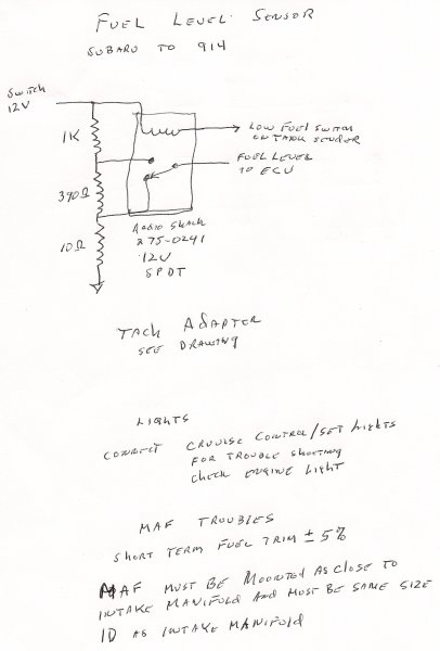 #4 Add Cruise control lights/Check engine lights for trouble shooting DTC’s #5 Make the 914 ignition key look like a Subaru ignition key for the immobilizer circuit 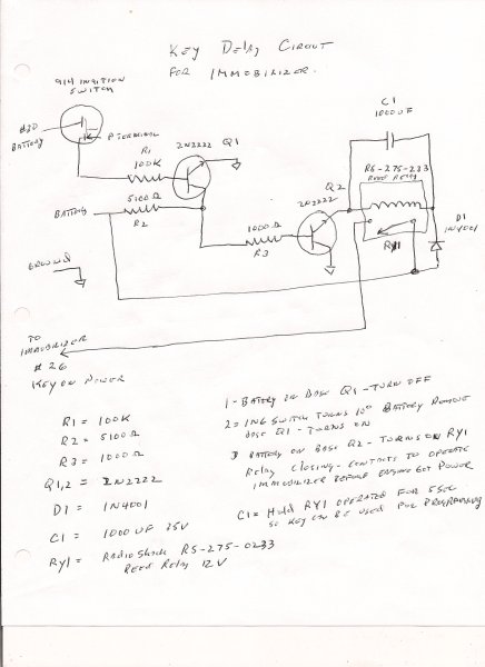 #6 Oil light and Oil pressure gauges/ Oil temperature gauge converted to Engine temperature gauge To convert Oil temperature to Water temperature gauge add a 75 ohm resistor in series with the extra temperature lead ( used for stock Subaru gauge panel) to the oil temp gauge If you have a Oil pressure/Oil light sender added to your gauge cluster just replace the Subaru Oil Pressure switch and use the same wiring otherwise just wire the Subaru sensor to the Oil lamp. Connect the Subaru alternator (Black/white) lead to the 914 Gen lamp bulb. If you see any poroblems let me know. Attached image(s) 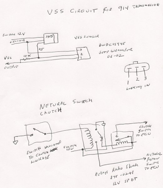
|
  |
Replies
| strawman |
 Dec 4 2012, 01:28 AM Dec 4 2012, 01:28 AM
Post
#2
|
|
Senior Member    Group: Members Posts: 888 Joined: 25-January 08 From: Los Osos, CA Member No.: 8,624 Region Association: Central California 
|
I was able to chase down most of the needed parts for the tach adapter from two different RatShacks in the area. However, it seems like the Audio Output Transformer (Part #273-1380, $2.99/each) is not drawn correctly in your diagram. See the image below for details from RatShack's website:
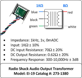 Here is also a picture of the back of the Audio Output Transformer package: 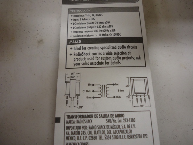 I am assuming the following: 1. The Q1 collector wire goes to the BLUE 1K-Ohm input on the transformer. 2. The Center Tap (BLACK) wire from transformer should intercept the cathode side of the diode on its way from the BLUE 1K-Ohm input wire (anode side) to the Green 1K-Ohm input of the transformer. 3. 12V ignition power goes to resistor R4 to GREEN 1K-Ohm input on the transformer (at the cathode intercept). 4. The RED 8-Ohm output wire on the transformer goes to the 914 tach signal. Where does the GREEN 8-Ohm output wire from the transformer go? I am not familiar with the "triangle" symbol that you used; does it signify ground? Also, how important is the wattage for resistor R4? RatShack only stocks 1-Watt 10-Ohm resistors in the store, but I can order 2-Watt 10-Ohm resistors (10 for $1.86 from RatShack online). Another question: what wattage is necessary for resistor R3? The local RatShack store only stocks 1/2-Watt 4.7k-Ohm resistors, but I can order 2-Watt 4.7k-Ohm resistors online (10 for $1.86 from RatShack). Finally, where does the emitter signal from transistor Q1 go? Again, I am not familiar with that triangle symbol you used... Thanks in advance! Geoff |
Posts in this topic
 904svo Subaru to 914 trouble fixes Dec 3 2012, 11:21 AM
 wingnut86 Hmmm, I like:-) Dec 3 2012, 02:37 PM
 strawman This is great info! I will build the tachomete... Dec 3 2012, 03:42 PM

 904svo
I was able to chase down most of the needed parts... Dec 4 2012, 07:36 AM
 euro911 This is some good stuff :thumbsup: Dec 4 2012, 01:49 AM
 dian very interesting.
what about the speedometer? Dec 4 2012, 03:16 AM

 904svo
very interesting.
what about the speedometer?
... Dec 4 2012, 07:41 AM
 904svo I mounted the circuit in a small case and installe... Dec 4 2012, 08:43 AM
 904svo Tach adapter in first post has been change to use ... Dec 4 2012, 11:07 AM
 strawman This is truly outstanding stuff, and I thank you f... Dec 4 2012, 01:05 PM
 strawman Larry really is a great guy, and we Suby-conversio... Dec 12 2012, 11:19 PM
 wingnut86 Agreed Strawman!
Once I give my wife "He... Dec 13 2012, 09:11 AM
 strawman The tach converter works! Be sure to follow th... Jan 1 2013, 02:29 PM
 jpnovak Reviving this thread to ask a question.
I have a... Jul 15 2013, 01:05 PM
 904svo On another post here they talk about a aftermarket... Jul 15 2013, 03:15 PM
 DBCooper Another option. This is mine, aftermarket VDO ele... Jul 15 2013, 03:39 PM
  |
1 User(s) are reading this topic (1 Guests and 0 Anonymous Users)
0 Members:

|
Lo-Fi Version | Time is now: 19th April 2025 - 03:48 PM |
Invision Power Board
v9.1.4 © 2025 IPS, Inc.


