|
|
|
Porsche, and the Porsche crest are registered trademarks of Dr. Ing. h.c. F. Porsche AG.
This site is not affiliated with Porsche in any way. Its only purpose is to provide an online forum for car enthusiasts. All other trademarks are property of their respective owners. |
|
|


| Spoke |
 Mar 30 2014, 09:35 PM Mar 30 2014, 09:35 PM
Post
#1
|
|
Jerry  Group: Members Posts: 7,052 Joined: 29-October 04 From: Allentown, PA Member No.: 3,031 Region Association: None |
On the radar are LED boards for the front turnsignal bucket. LEDs would be pointing directly to the front of the car to focus optical energy forward.
There are 3 versions I can think of: 1) US lens: All amber LEDs; all on low for running lights; on high for turnsignals. 2) Euro lens: White LEDs on the lower section; on for running lights; amber for turnsignals. White LEDs would turn off when turnsignals are on. 3) Clear lens: White running LEDs on the outside of the lens; Amber LEDs in the center for turnsignals. White LEDs would turn off when turnsignals are on. Which versions would folks want? I think I would like the clear lens. The oval running lights would be unique. Mock up of turnsignal LED PCB. 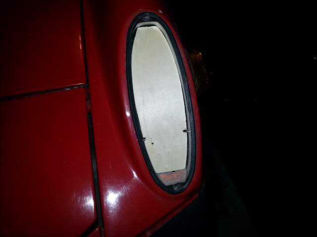 PCB for clear lens. 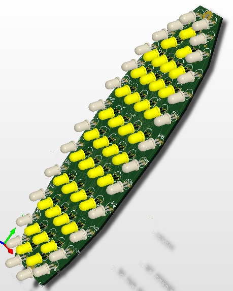 PCB for Euro lens. 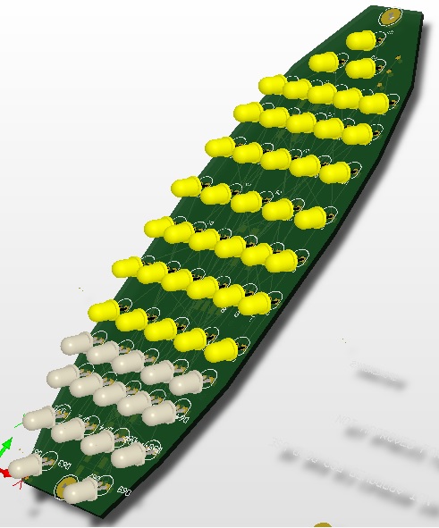 |
   |

 
|
  |
Replies
| Spoke |
Jun 26 2014, 09:16 PM
Post
#2
|
|
Jerry Group: Members Posts: 7,052 Joined: 29-October 04 From: Allentown, PA Member No.: 3,031 Region Association: None |
Had some down time on the rear LED boards while my buddy's 3d printer was repaired and the flow of plastic clips dried up so I worked the layout of the front LED boards.
Seems more interest in the Euro front bucket so I'm starting with that version. It would be ideal to make a universal board do US and Euro format unfortunately the white running light LEDs have a higher voltage drop than the amber thus 3 white LEDs are in series versus 4 amber LEDs per string. Therefore it's difficult to make a Euro board into a US board. Here's some 3d drawings of the board so far. The board has 48 amber turnsignal LEDs and 21 white running light LEDs. There will be a configuration option with the Euro lights: The amber turnsignal LEDs can be configured to be dimly on for running lights or off for running lights. Here's what the board looks like now when viewed from the front of the 914. 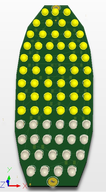 Here's a side view of the board. As SirAndy pointed out with the rear lights, the dispersion angle is tight with these LEDs so they must be pointing in the direction that light is intended; that is directly in front of the car. Mounting them perpendicular to the board will not do as the light will be pointed into the sky at about a 45 degree angle. 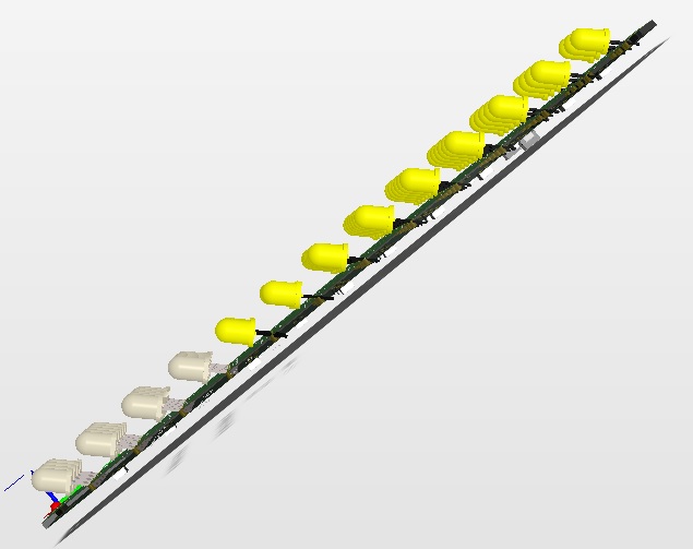 This pic shows a close-up of the one difficulty with the LED angle that I'm trying to solve. Unlike this pic of the board, the leads will be bent and perpendicular though the board. Somehow the LED has to be soldered about 3/16 of an inch off the board then leads bent so the LED is at about a 45 degree angle. That's one issue. The second is once the leads are bent, how to take the stress of securing the LED off of the soft solder on the leads. Eventually the vehicle vibration through the LED bodies will wear out the solder and the solder will fail. Somehow the body of the LED must be secured to the board by other mechanical means. Right now I'm thinking about conformal coating or caulking of some sort. Any ideas on soldering the LEDs 3/16" off the board or securing the body to the board are welcome. 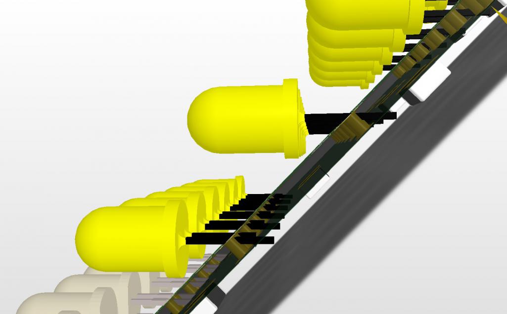 |
|
|
|
| mobymutt |
Aug 4 2014, 08:14 PM
Post
#3
|
|
Senior Member Group: Members Posts: 553 Joined: 16-December 13 From: Kingston, Ontario, Canada Member No.: 16,770 Region Association: Canada |
QUOTE(Spoke @ Jun 26 2014, 11:16 PM)  That's one issue. The second is once the leads are bent, how to take the stress of securing the LED off of the soft solder on the leads. Eventually the vehicle vibration through the LED bodies will wear out the solder and the solder will fail. Somehow the body of the LED must be secured to the board by other mechanical means. Right now I'm thinking about conformal coating or caulking of some sort. Any ideas on soldering the LEDs 3/16" off the board or securing the body to the board are welcome. I know nothing about circuit board design, but that won't stop me from chiming in on this. BTW, I think both these lights and the LED tail lights are awesome, they are on my Christmas list. First, I am not convinced that the vibrational stress on the soldered connections will really be all that different on the long bent leads vs the standard ones. That being said, I understand your concern, better to be safe than sorry! What if you make a 3D printed support that follows the profile of the circuit board, but is stair-shaped in cross section -- this support piece would go between the LEDs and the circuit board, and provide secure support for the bulbs. Perhaps you could integrate the bucket mounting features into it as well. I can model something up if you think this idea has any merit, just PM me. |
|
|
|
Posts in this topic
 Spoke LEDs For Front Turnsignal Bucket Mar 30 2014, 09:35 PM
 R8CERX
On the radar are LED boards for the front turnsig... Mar 30 2014, 11:47 PM Cairo94507 Outstanding!!!! Mar 31 2014, 05:56 AM Chris H. Update...I want the US version (#1). Mar 31 2014, 06:19 AM Harpo Awesome can't wait
David Mar 31 2014, 06:22 AM CptTripps So is this right for #3? Mar 31 2014, 07:33 AM
R8CERX
On the radar are LED boards for the front turnsig... Mar 30 2014, 11:47 PM Cairo94507 Outstanding!!!! Mar 31 2014, 05:56 AM Chris H. Update...I want the US version (#1). Mar 31 2014, 06:19 AM Harpo Awesome can't wait
David Mar 31 2014, 06:22 AM CptTripps So is this right for #3? Mar 31 2014, 07:33 AM
 Spoke
So is this right for #3?
I was thinking just th... Mar 31 2014, 11:51 AM CptTripps
I was thinking just the outer ring of white LEDs ... Mar 31 2014, 11:55 AM Chris H. That looks cool! Reverse euro lens. You coul... Mar 31 2014, 07:45 AM JmuRiz Very cool, "PCB for clear lens" would lo... Mar 31 2014, 07:59 AM Zimms I am in for Euro lights Mar 31 2014, 08:22 AM JmuRiz The white daylight running light ring going off wh... Mar 31 2014, 12:40 PM Spoke
The white daylight running light ring going off w... Mar 31 2014, 03:03 PM mrholland2
The white daylight running light ring going off ... Mar 31 2014, 03:57 PM mrholland2
[quote name='Spoke' post='2018545' date='Mar 31 2... Mar 31 2014, 04:25 PM Cairo94507 My 997.2 has the front LED running lights and when... Mar 31 2014, 03:36 PM mrholland2 Soooooo do we have a final answer on this? I love... Apr 2 2014, 11:40 PM Spoke
Soooooo do we have a final answer on this? I lov... Apr 2 2014, 11:59 PM mrholland2 Sooooo. . what if I want to use the Euro version w... Apr 3 2014, 01:59 PM Spoke
Sooooo. . what if I want to use the Euro version ... Apr 3 2014, 04:11 PM 69telecaster Aren't original bulbs white on US models?
Woul... Apr 3 2014, 06:56 AM CptTripps
Wouldn't white LED's behind the amber len... Apr 3 2014, 07:22 AM Spoke
Wouldn't white LED's behind the amber le... Apr 3 2014, 09:37 AM 914Mike
This was posted in my LED brake thread. One pict... Aug 4 2014, 11:18 AM chads74 I would love a set. I am keeping my fingers crosse... Apr 3 2014, 07:47 AM morgan_harwell I like #2 for my 914:
2) Euro lens: White LEDs o... Apr 3 2014, 03:39 PM ConeDodger EUR[color=#FFFFFF][size=7]O
please... :) Apr 3 2014, 04:14 PM euro911 [size=7]EUR[color=#FFFFFF][size=7]O
please... :)... Aug 4 2014, 11:57 PM john77 I'm in for a set, just not sure which one. I h... Apr 3 2014, 04:48 PM StratPlayer I'd be in for a set of the Euro's Apr 3 2014, 06:12 PM scottb in for euro pair Apr 3 2014, 06:25 PM zambezi I would be in for one set as well. I have the cle... Apr 3 2014, 08:37 PM cconcepcion euro por favor! 1 pair with blanking feature..... Apr 5 2014, 05:04 PM Zimms I am in for 1 pair of euros Apr 5 2014, 10:23 PM monkeyboy 1 set of Euros when they are ready. Thank you. Apr 6 2014, 12:45 AM Rleog Add me to the Euro lens list. Apr 8 2014, 10:21 AM McMark It would add to build cost, of course, but a selec... Apr 8 2014, 11:35 AM zymurgist I like the Euro idea. May want to run with amber ... Apr 8 2014, 11:43 AM IanS I would like an amber set please Mr. Spoke Apr 8 2014, 11:56 AM Harpo Good morning Jerry,
Any update on the Front turn ... Jun 14 2014, 10:12 AM 75-914 Euro for me too! Jun 14 2014, 11:14 AM tomeric914 Jerry, you suck. Now I HAVE to buy these too. :... Jun 14 2014, 08:31 PM sportlicherFahrer +1 for front Euro as well please! REALLY like... Jun 15 2014, 02:49 AM jacksun just and idea to be used or not.
why not tie in t... Jun 15 2014, 06:12 AM orthobiz US lens for me. Especially after my rear kit arriv... Jun 15 2014, 06:45 AM Spoke Haven't made too much progress on the fronts. ... Jun 15 2014, 07:10 AM GermermanCarGuy
Haven't made too much progress on the fronts.... Aug 4 2014, 06:46 PM 75-914 sent PM Jun 19 2014, 08:09 PM swooshdave Drill the holes at an angle? Jun 26 2014, 09:40 PM sportlicherFahrer Rubber support strips under each row, or clear pla... Jun 26 2014, 09:48 PM tomeric914 Build a jig to prebend LED leads at a 45 degree an... Jun 26 2014, 10:12 PM Spoke Just about ready to fab the first prototypes of th... Jul 20 2014, 06:55 AM cary I'm in for a US version pair. Changed my mind,... Jul 20 2014, 07:44 AM Zimms I am in for option 2 Jul 20 2014, 08:20 AM sportlicherFahrer Still in for one set of option 1 please. Jul 20 2014, 08:24 AM Spoke The first prototype boards arrived today. The fit ... Aug 4 2014, 10:03 AM JmuRiz Very cool stuff, are you going to do one like in p... Aug 4 2014, 10:14 AM Cairo94507 Hi Spoke:
I am hoping that when Scotty is ready f... Aug 4 2014, 01:04 PM Harpo Thanks for the update. Looks good
David Aug 4 2014, 04:17 PM mikesmith Rather than bend the leads, just increase the dril... Aug 4 2014, 11:21 PM Steve Depending on cost, I will take a set of Euro LED... Aug 4 2014, 11:34 PM CptTripps If you're worried about vibration, you could a... Aug 5 2014, 07:20 AM Spoke Thanks all for ideas on mounting the LEDs. We... Aug 5 2014, 11:31 AM kid914 :Qarl: in for a US set. I still have to order th... Aug 5 2014, 02:33 PM john77 In for a set to go with my rears. Aug 5 2014, 02:35 PM eric9144 In for a US set... :beer2: Aug 5 2014, 05:02 PM Spoke Built up the first prototype; except for 3 white L... Aug 8 2014, 10:01 AM euro911 Jerry, if the upper end of the board sits further ... Aug 8 2014, 05:25 PM Spoke
Jerry, if the upper end of the board sits further... Aug 12 2014, 03:33 PM Harpo Looks awesome Jerry +1 euro
David Aug 8 2014, 06:21 PM speed metal army Yep! In for a set of fronts and rears as soon ... Aug 8 2014, 10:38 PM Spoke Took a couple of videos of the front LEDs. This is... Aug 10 2014, 09:06 PM JmuRiz Is there anyway to turn the running light off when... Aug 11 2014, 11:51 AM Spoke
Is there anyway to turn the running light off whe... Aug 12 2014, 03:41 PM mikesmith
I thought about adding the blanking feature but s... Aug 14 2014, 09:58 AM euro911 In both video clips, are the driver side lamps the... Aug 11 2014, 03:15 PM Spoke
In both video clips, are the driver side lamps th... Aug 12 2014, 03:36 PM Chris H. Yep that's what it looks like. I just updated... Aug 11 2014, 06:41 PM IanS Those look amazing! I think I already replied... Aug 12 2014, 09:38 AM CptTripps You know me...I'm in. Aug 12 2014, 10:06 AM db9146 I'm in for a pair of Euros. Nice. Aug 13 2014, 12:21 PM Spoke Couple more videos of the front LEDs. This is the ... Aug 15 2014, 02:09 PM euro911 Couple more videos of the front LEDs. This is the ... Aug 21 2014, 02:41 AM Cairo94507 WOW! :first: Those front LED's are terri... Aug 16 2014, 07:40 AM Firstcar Euro version with the white running lights looks g... Aug 16 2014, 08:22 AM kid914 First off, Spoke, you do awesome work at keeping U... Aug 16 2014, 09:42 AM siverson Very nice. I'll be in for a set when ready.
A... Aug 16 2014, 10:13 AM clapeza I'm in for a Euro set, when available. Awesome... Aug 16 2014, 10:25 AM rnellums Not sure if I posted yet, but I love my rear LED... Aug 17 2014, 10:30 PM CptTripps As always....they look perfect.
I'm in for Eu... Aug 18 2014, 06:47 AM BuddyV 914 people are friggin awesome..... thank you for ... Aug 21 2014, 08:12 AM Spoke I'd like to ask a favor of anyone interested i... Aug 21 2014, 09:12 PM mikesmith +1 for a LED-compatible flasher. Aug 21 2014, 11:06 PM Spoke
+1 for a LED-compatible flasher.
I only wish it... Aug 23 2014, 05:56 PM mikesmith
If anyone has implemented an LED-compatible flash... Aug 29 2014, 09:58 PM lawnvett
If anyone has implemented an LED-compatible flas... Aug 29 2014, 11:18 PM Spoke
I have a no-name Chinese LED-capable EP26 flasher... Aug 30 2014, 06:56 AM montoya 73 2.0 Put me down for euro fronts and possibly a 2nd pai... Aug 29 2014, 11:59 PM
Spoke
So is this right for #3?
I was thinking just th... Mar 31 2014, 11:51 AM CptTripps
I was thinking just the outer ring of white LEDs ... Mar 31 2014, 11:55 AM Chris H. That looks cool! Reverse euro lens. You coul... Mar 31 2014, 07:45 AM JmuRiz Very cool, "PCB for clear lens" would lo... Mar 31 2014, 07:59 AM Zimms I am in for Euro lights Mar 31 2014, 08:22 AM JmuRiz The white daylight running light ring going off wh... Mar 31 2014, 12:40 PM Spoke
The white daylight running light ring going off w... Mar 31 2014, 03:03 PM mrholland2
The white daylight running light ring going off ... Mar 31 2014, 03:57 PM mrholland2
[quote name='Spoke' post='2018545' date='Mar 31 2... Mar 31 2014, 04:25 PM Cairo94507 My 997.2 has the front LED running lights and when... Mar 31 2014, 03:36 PM mrholland2 Soooooo do we have a final answer on this? I love... Apr 2 2014, 11:40 PM Spoke
Soooooo do we have a final answer on this? I lov... Apr 2 2014, 11:59 PM mrholland2 Sooooo. . what if I want to use the Euro version w... Apr 3 2014, 01:59 PM Spoke
Sooooo. . what if I want to use the Euro version ... Apr 3 2014, 04:11 PM 69telecaster Aren't original bulbs white on US models?
Woul... Apr 3 2014, 06:56 AM CptTripps
Wouldn't white LED's behind the amber len... Apr 3 2014, 07:22 AM Spoke
Wouldn't white LED's behind the amber le... Apr 3 2014, 09:37 AM 914Mike
This was posted in my LED brake thread. One pict... Aug 4 2014, 11:18 AM chads74 I would love a set. I am keeping my fingers crosse... Apr 3 2014, 07:47 AM morgan_harwell I like #2 for my 914:
2) Euro lens: White LEDs o... Apr 3 2014, 03:39 PM ConeDodger EUR[color=#FFFFFF][size=7]O
please... :) Apr 3 2014, 04:14 PM euro911 [size=7]EUR[color=#FFFFFF][size=7]O
please... :)... Aug 4 2014, 11:57 PM john77 I'm in for a set, just not sure which one. I h... Apr 3 2014, 04:48 PM StratPlayer I'd be in for a set of the Euro's Apr 3 2014, 06:12 PM scottb in for euro pair Apr 3 2014, 06:25 PM zambezi I would be in for one set as well. I have the cle... Apr 3 2014, 08:37 PM cconcepcion euro por favor! 1 pair with blanking feature..... Apr 5 2014, 05:04 PM Zimms I am in for 1 pair of euros Apr 5 2014, 10:23 PM monkeyboy 1 set of Euros when they are ready. Thank you. Apr 6 2014, 12:45 AM Rleog Add me to the Euro lens list. Apr 8 2014, 10:21 AM McMark It would add to build cost, of course, but a selec... Apr 8 2014, 11:35 AM zymurgist I like the Euro idea. May want to run with amber ... Apr 8 2014, 11:43 AM IanS I would like an amber set please Mr. Spoke Apr 8 2014, 11:56 AM Harpo Good morning Jerry,
Any update on the Front turn ... Jun 14 2014, 10:12 AM 75-914 Euro for me too! Jun 14 2014, 11:14 AM tomeric914 Jerry, you suck. Now I HAVE to buy these too. :... Jun 14 2014, 08:31 PM sportlicherFahrer +1 for front Euro as well please! REALLY like... Jun 15 2014, 02:49 AM jacksun just and idea to be used or not.
why not tie in t... Jun 15 2014, 06:12 AM orthobiz US lens for me. Especially after my rear kit arriv... Jun 15 2014, 06:45 AM Spoke Haven't made too much progress on the fronts. ... Jun 15 2014, 07:10 AM GermermanCarGuy
Haven't made too much progress on the fronts.... Aug 4 2014, 06:46 PM 75-914 sent PM Jun 19 2014, 08:09 PM swooshdave Drill the holes at an angle? Jun 26 2014, 09:40 PM sportlicherFahrer Rubber support strips under each row, or clear pla... Jun 26 2014, 09:48 PM tomeric914 Build a jig to prebend LED leads at a 45 degree an... Jun 26 2014, 10:12 PM Spoke Just about ready to fab the first prototypes of th... Jul 20 2014, 06:55 AM cary I'm in for a US version pair. Changed my mind,... Jul 20 2014, 07:44 AM Zimms I am in for option 2 Jul 20 2014, 08:20 AM sportlicherFahrer Still in for one set of option 1 please. Jul 20 2014, 08:24 AM Spoke The first prototype boards arrived today. The fit ... Aug 4 2014, 10:03 AM JmuRiz Very cool stuff, are you going to do one like in p... Aug 4 2014, 10:14 AM Cairo94507 Hi Spoke:
I am hoping that when Scotty is ready f... Aug 4 2014, 01:04 PM Harpo Thanks for the update. Looks good
David Aug 4 2014, 04:17 PM mikesmith Rather than bend the leads, just increase the dril... Aug 4 2014, 11:21 PM Steve Depending on cost, I will take a set of Euro LED... Aug 4 2014, 11:34 PM CptTripps If you're worried about vibration, you could a... Aug 5 2014, 07:20 AM Spoke Thanks all for ideas on mounting the LEDs. We... Aug 5 2014, 11:31 AM kid914 :Qarl: in for a US set. I still have to order th... Aug 5 2014, 02:33 PM john77 In for a set to go with my rears. Aug 5 2014, 02:35 PM eric9144 In for a US set... :beer2: Aug 5 2014, 05:02 PM Spoke Built up the first prototype; except for 3 white L... Aug 8 2014, 10:01 AM euro911 Jerry, if the upper end of the board sits further ... Aug 8 2014, 05:25 PM Spoke
Jerry, if the upper end of the board sits further... Aug 12 2014, 03:33 PM Harpo Looks awesome Jerry +1 euro
David Aug 8 2014, 06:21 PM speed metal army Yep! In for a set of fronts and rears as soon ... Aug 8 2014, 10:38 PM Spoke Took a couple of videos of the front LEDs. This is... Aug 10 2014, 09:06 PM JmuRiz Is there anyway to turn the running light off when... Aug 11 2014, 11:51 AM Spoke
Is there anyway to turn the running light off whe... Aug 12 2014, 03:41 PM mikesmith
I thought about adding the blanking feature but s... Aug 14 2014, 09:58 AM euro911 In both video clips, are the driver side lamps the... Aug 11 2014, 03:15 PM Spoke
In both video clips, are the driver side lamps th... Aug 12 2014, 03:36 PM Chris H. Yep that's what it looks like. I just updated... Aug 11 2014, 06:41 PM IanS Those look amazing! I think I already replied... Aug 12 2014, 09:38 AM CptTripps You know me...I'm in. Aug 12 2014, 10:06 AM db9146 I'm in for a pair of Euros. Nice. Aug 13 2014, 12:21 PM Spoke Couple more videos of the front LEDs. This is the ... Aug 15 2014, 02:09 PM euro911 Couple more videos of the front LEDs. This is the ... Aug 21 2014, 02:41 AM Cairo94507 WOW! :first: Those front LED's are terri... Aug 16 2014, 07:40 AM Firstcar Euro version with the white running lights looks g... Aug 16 2014, 08:22 AM kid914 First off, Spoke, you do awesome work at keeping U... Aug 16 2014, 09:42 AM siverson Very nice. I'll be in for a set when ready.
A... Aug 16 2014, 10:13 AM clapeza I'm in for a Euro set, when available. Awesome... Aug 16 2014, 10:25 AM rnellums Not sure if I posted yet, but I love my rear LED... Aug 17 2014, 10:30 PM CptTripps As always....they look perfect.
I'm in for Eu... Aug 18 2014, 06:47 AM BuddyV 914 people are friggin awesome..... thank you for ... Aug 21 2014, 08:12 AM Spoke I'd like to ask a favor of anyone interested i... Aug 21 2014, 09:12 PM mikesmith +1 for a LED-compatible flasher. Aug 21 2014, 11:06 PM Spoke
+1 for a LED-compatible flasher.
I only wish it... Aug 23 2014, 05:56 PM mikesmith
If anyone has implemented an LED-compatible flash... Aug 29 2014, 09:58 PM lawnvett
If anyone has implemented an LED-compatible flas... Aug 29 2014, 11:18 PM Spoke
I have a no-name Chinese LED-capable EP26 flasher... Aug 30 2014, 06:56 AM montoya 73 2.0 Put me down for euro fronts and possibly a 2nd pai... Aug 29 2014, 11:59 PM |
3 User(s) are reading this topic (3 Guests and 0 Anonymous Users)
0 Members:

|
Lo-Fi Version | Time is now: 28th September 2024 - 07:17 AM |
Invision Power Board
v9.1.4 © 2024 IPS, Inc.