|
|
|
Porsche, and the Porsche crest are registered trademarks of Dr. Ing. h.c. F. Porsche AG.
This site is not affiliated with Porsche in any way. Its only purpose is to provide an online forum for car enthusiasts. All other trademarks are property of their respective owners. |
|
|


| Tom |
 May 3 2014, 01:30 PM May 3 2014, 01:30 PM
Post
#1
|
|
Advanced Member  Group: Members Posts: 2,139 Joined: 21-August 05 From: Port Orchard, WA 98367 Member No.: 4,626 Region Association: None |
After reading many accounts of how this circuit works, I felt compelled to investigate further as I did not understand how two positives would cause a light to operate. They won't. One must be somewhat negative to complete the circuit. Internet searches turned up the same basic explanation, still was not buying it. I think it was being oversimplified.
This is how I think the alt light works: When the key is on and engine not running, there is 12 volts + at the alt light power side coming from the fused side of fuse #9. The other side goes to a junction on the relay board with D+. With the key to off and a meter connected between D+ and ground at the relay board, the reading is 12 ohms. As soon as the key is turned to on, the reading jumps to 12.5 meg ohms and the light comes on. If the wire for D+ to the alt is removed, the reading stays the same and the light stays on. Removing the VR caused the reading to jump to infinity and the light goes out. For the light to work, there has to be power to one side of the light and some resistance reading to ground for the other. Looking at the wiring diagram, one can follow the blue wire to the junction at the relay board at D+, then up thru the VR to a set of relay contacts, then down thru a ( resistor ?, not sure) and then down to the DF connection and on to the rotor where the current will produce a magnetic field. After the rotor, it goes to ground. When the alt spins enough RPM's, a voltage is produced and fed back to the VR, causing the relay to open and removes the ground path for the alt light. I could be entirely wrong here, but this is what I see and my readings more or less confirm it. If you see an error in my thinking, please post and let me know. Thanks, Tom Attached thumbnail(s) 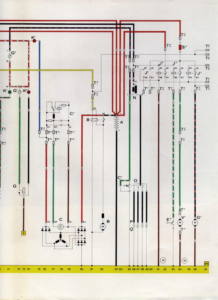
|
   |

 
|
  |
Replies
| Spoke |
Sep 5 2014, 10:27 AM
Post
#2
|
|
Jerry Group: Members Posts: 7,051 Joined: 29-October 04 From: Allentown, PA Member No.: 3,031 Region Association: None |
Alternator testing good may not completely test all the functions of the alternator. Not sure the test would find a damaged diode on the charging or VR sides.
Here's a little description of how the diodes work in the alternator. The alternator is a 3-phase alternator with 3 separate windings spaced 120 degrees from each other. With full diode bridge rectification, the correct alternator output across the VR would look something like this. The black line is actual voltage since the VR has some capacitance to filter the ripple voltage from the alternator. 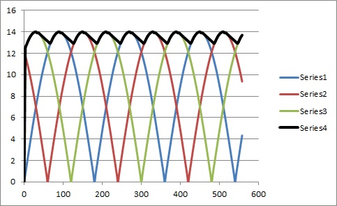 If you lose one phase of the alternator because of a open circuited diode, the voltage would droop between the operating phases and the GEN light would light a bit. 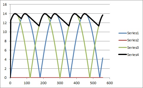 If 2 phases are lost, the droop in the voltage is more pronounced and the GEN light is brighter. 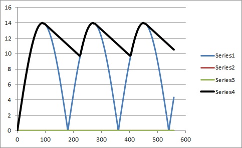 So with burnt diodes, the GEN light is on at idle, rev the engine and the GEN light dims. This is because there is less time between active phases of the black trace, the voltage across the VR and one side of the GEN light is almost 14V like across the battery on the other side of the GEN light. 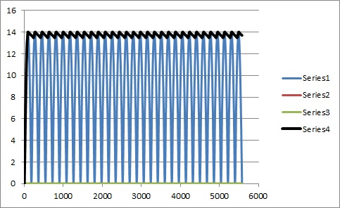 |
|
|
|
| type47 |
Sep 5 2014, 03:21 PM
Post
#3
|
|
Viermeister Group: Members Posts: 4,254 Joined: 7-August 03 From: Vienna, VA Member No.: 994 Region Association: MidAtlantic Region |
QUOTE(Spoke @ Sep 5 2014, 08:27 AM)  Alternator testing good may not completely test all the functions of the alternator. Not sure the test would find a damaged diode on the charging or VR sides. Tested at Advance Auto parts. I really don't want to R & R the alt again. When I started and revved the engine, the light did not dim. I need to get out and measure voltages on either side of the alt light. I think I can get the DMM probe in the plugs. First try did not get 12 V but about 3 V. Had to stop for other things ... So on either side of the alt light there should be 12 V? That's what I read from the above info. So the alt terminal D+ found in track 76 in the schematic should be 12 V. The terminals T 3a, T 3b are the plug for the alt harness on the relay board and T 14/2 connects there too; I should be able to measure at the plug... |
|
|
|
Posts in this topic
 Tom How alternator light works May 3 2014, 01:30 PM
 bulitt I recall you need a light or resistor to "exc... May 3 2014, 01:47 PM toolguy Light comes on when the alternator out voltage on ... May 3 2014, 02:38 PM Spoke
I could be entirely wrong here, but this is what ... May 3 2014, 03:47 PM Dave_Darling A couple of minor misconceptions in the OP:
The l... May 3 2014, 04:24 PM
bulitt I recall you need a light or resistor to "exc... May 3 2014, 01:47 PM toolguy Light comes on when the alternator out voltage on ... May 3 2014, 02:38 PM Spoke
I could be entirely wrong here, but this is what ... May 3 2014, 03:47 PM Dave_Darling A couple of minor misconceptions in the OP:
The l... May 3 2014, 04:24 PM
 type47
... and there are other failure modes that will m... Aug 26 2014, 06:41 AM Dave_Darling
Could you expand on this?
If some of your altern... Aug 26 2014, 09:23 AM 76-914 :wacko: Wow! I'm still a little dazed but ... May 3 2014, 04:50 PM worn
After reading many accounts of how this circuit w... May 3 2014, 07:47 PM stugray Every one else covered the basics very well above.... May 3 2014, 09:21 PM Tom stugray,
OMG, you are so right! I don... May 4 2014, 12:44 PM ThePaintedMan Check the voltage regulator. Aug 26 2014, 07:46 AM stugray There is a test where you unplug the VR and connec... Aug 26 2014, 08:05 AM type47 The alt I removed this morning and tested good has... Aug 26 2014, 10:33 AM type47 So, there is no joy in Mudville, the alt light is ... Sep 5 2014, 09:21 AM Spoke Remove the gauge bucket with the GEN light. Start ... Sep 5 2014, 04:02 PM type47
...what is the battery voltage when the car is id... Sep 9 2014, 04:57 PM The Cabinetmaker Last time I saw a bad vr I replaced it with the so... Sep 5 2014, 04:10 PM type47
Last time I saw a bad vr I replaced it with the s... Sep 5 2014, 05:29 PM Dave_Darling If that's the voltage across the battery posts... Sep 9 2014, 11:55 PM GregAmy So instead of starting a new thread, I'm going... Jul 27 2019, 09:25 AM Spoke I would take a guess at about 200 ohm should do. B... Jul 27 2019, 10:14 AM mikesmith
After reading many accounts of how this circuit w... Jul 28 2019, 01:24 PM GregAmy That's some beautiful stuff right there (along... Jul 29 2019, 02:51 PM Spoke
That's some beautiful stuff right there (alon... Jul 29 2019, 08:24 PM mikesmith
- After posting, I took the racer out for a spin ... Jul 29 2019, 03:42 PM GregAmy Your description just begs more questions, sadly. ... Jul 29 2019, 07:56 PM 930cabman Another old, old thread
Generator light will not ... Jul 10 2024, 04:52 PM Spoke
Another old, old thread
Generator light will not... Jul 11 2024, 11:15 PM 930cabman
[quote name='930cabman' post='3155854' date='Jul ... Jul 12 2024, 04:59 AM Spoke
Thank you Spoke, this issue is with a recent /6 c... Jul 12 2024, 07:58 AM Lucky9146 Glad this thread got bumped, the diagrams and info... Jul 11 2024, 11:17 PM ClayPerrine This sounds like an issue with bad grounds.
Was... Jul 12 2024, 05:32 AM 930cabman
This sounds like an issue with bad grounds.
Wa... Jul 12 2024, 05:38 AM 87m491 Not for nothing, but unless I missed it you have n... Jul 12 2024, 06:30 AM technicalninja Spoke and Dave Darling have their shit together... Jul 12 2024, 08:18 AM 930cabman Once again, the 914 World Team has killed it.
Now... Jul 12 2024, 09:13 AM 930cabman Excited
Still having an issue, but seems as thoug... Jul 14 2024, 04:32 PM Superhawk996
Excited
Still having an issue, but seems as thou... Jul 14 2024, 05:44 PM 930cabman
[quote name='930cabman' post='3156695' date='Jul ... Jul 15 2024, 11:29 AM Superhawk996
When you say blue wire has nothing on it is th... Jul 15 2024, 12:57 PM 930cabman
[quote name='930cabman' post='3156853' date='Jul ... Jul 15 2024, 01:00 PM Superhawk996
maybe the bulb wattage is not allowing the alte... Jul 15 2024, 01:14 PM 930cabman
maybe the bulb wattage is not allowing the alt... Jul 15 2024, 01:20 PM Superhawk996
After a few blips she starts charging and stays... Jul 15 2024, 01:33 PM Spoke
Excited
Still having an issue, but seems as thou... Jul 15 2024, 08:23 AM 930cabman
Excited
Still having an issue, but seems as tho... Jul 15 2024, 09:21 AM 930cabman Got it, mostly. As you can imagine this has been d... Jul 15 2024, 04:25 PM Superhawk996
Got it, mostly. As you can imagine this has been ... Jul 15 2024, 05:02 PM 930cabman
Got it, mostly. As you can imagine this has been... Jul 15 2024, 06:19 PM
type47
... and there are other failure modes that will m... Aug 26 2014, 06:41 AM Dave_Darling
Could you expand on this?
If some of your altern... Aug 26 2014, 09:23 AM 76-914 :wacko: Wow! I'm still a little dazed but ... May 3 2014, 04:50 PM worn
After reading many accounts of how this circuit w... May 3 2014, 07:47 PM stugray Every one else covered the basics very well above.... May 3 2014, 09:21 PM Tom stugray,
OMG, you are so right! I don... May 4 2014, 12:44 PM ThePaintedMan Check the voltage regulator. Aug 26 2014, 07:46 AM stugray There is a test where you unplug the VR and connec... Aug 26 2014, 08:05 AM type47 The alt I removed this morning and tested good has... Aug 26 2014, 10:33 AM type47 So, there is no joy in Mudville, the alt light is ... Sep 5 2014, 09:21 AM Spoke Remove the gauge bucket with the GEN light. Start ... Sep 5 2014, 04:02 PM type47
...what is the battery voltage when the car is id... Sep 9 2014, 04:57 PM The Cabinetmaker Last time I saw a bad vr I replaced it with the so... Sep 5 2014, 04:10 PM type47
Last time I saw a bad vr I replaced it with the s... Sep 5 2014, 05:29 PM Dave_Darling If that's the voltage across the battery posts... Sep 9 2014, 11:55 PM GregAmy So instead of starting a new thread, I'm going... Jul 27 2019, 09:25 AM Spoke I would take a guess at about 200 ohm should do. B... Jul 27 2019, 10:14 AM mikesmith
After reading many accounts of how this circuit w... Jul 28 2019, 01:24 PM GregAmy That's some beautiful stuff right there (along... Jul 29 2019, 02:51 PM Spoke
That's some beautiful stuff right there (alon... Jul 29 2019, 08:24 PM mikesmith
- After posting, I took the racer out for a spin ... Jul 29 2019, 03:42 PM GregAmy Your description just begs more questions, sadly. ... Jul 29 2019, 07:56 PM 930cabman Another old, old thread
Generator light will not ... Jul 10 2024, 04:52 PM Spoke
Another old, old thread
Generator light will not... Jul 11 2024, 11:15 PM 930cabman
[quote name='930cabman' post='3155854' date='Jul ... Jul 12 2024, 04:59 AM Spoke
Thank you Spoke, this issue is with a recent /6 c... Jul 12 2024, 07:58 AM Lucky9146 Glad this thread got bumped, the diagrams and info... Jul 11 2024, 11:17 PM ClayPerrine This sounds like an issue with bad grounds.
Was... Jul 12 2024, 05:32 AM 930cabman
This sounds like an issue with bad grounds.
Wa... Jul 12 2024, 05:38 AM 87m491 Not for nothing, but unless I missed it you have n... Jul 12 2024, 06:30 AM technicalninja Spoke and Dave Darling have their shit together... Jul 12 2024, 08:18 AM 930cabman Once again, the 914 World Team has killed it.
Now... Jul 12 2024, 09:13 AM 930cabman Excited
Still having an issue, but seems as thoug... Jul 14 2024, 04:32 PM Superhawk996
Excited
Still having an issue, but seems as thou... Jul 14 2024, 05:44 PM 930cabman
[quote name='930cabman' post='3156695' date='Jul ... Jul 15 2024, 11:29 AM Superhawk996
When you say blue wire has nothing on it is th... Jul 15 2024, 12:57 PM 930cabman
[quote name='930cabman' post='3156853' date='Jul ... Jul 15 2024, 01:00 PM Superhawk996
maybe the bulb wattage is not allowing the alte... Jul 15 2024, 01:14 PM 930cabman
maybe the bulb wattage is not allowing the alt... Jul 15 2024, 01:20 PM Superhawk996
After a few blips she starts charging and stays... Jul 15 2024, 01:33 PM Spoke
Excited
Still having an issue, but seems as thou... Jul 15 2024, 08:23 AM 930cabman
Excited
Still having an issue, but seems as tho... Jul 15 2024, 09:21 AM 930cabman Got it, mostly. As you can imagine this has been d... Jul 15 2024, 04:25 PM Superhawk996
Got it, mostly. As you can imagine this has been ... Jul 15 2024, 05:02 PM 930cabman
Got it, mostly. As you can imagine this has been... Jul 15 2024, 06:19 PM |
14 User(s) are reading this topic (14 Guests and 0 Anonymous Users)
0 Members:

|
Lo-Fi Version | Time is now: 18th September 2024 - 07:23 PM |
Invision Power Board
v9.1.4 © 2024 IPS, Inc.