|
|
|
Porsche, and the Porsche crest are registered trademarks of Dr. Ing. h.c. F. Porsche AG.
This site is not affiliated with Porsche in any way. Its only purpose is to provide an online forum for car enthusiasts. All other trademarks are property of their respective owners. |
|
|


| skeates |
 Jul 29 2014, 09:57 PM Jul 29 2014, 09:57 PM
Post
#1
|
|
Member  Group: Members Posts: 219 Joined: 28-February 05 From: Sacramento, ca Member No.: 3,684 Region Association: Northern California |
Hey guys - I'm not sure if this is a subject that has been beaten to death before (I certainly wasn't able to find any threads on it), but has anyone here ever attempted to make use of the boxster or cousin 996 gauge clusters in a conversion? I was able to find a pin-out diagram for the boxster cluster which makes it look doable. Just curious if there was any fancy shmancy communications between the cluster and the ECU that would need to be worked around?
|
   |

 
|
  |
Replies
| skeates |
Sep 15 2014, 01:07 PM
Post
#2
|
|
Member Group: Members Posts: 219 Joined: 28-February 05 From: Sacramento, ca Member No.: 3,684 Region Association: Northern California |
So, until someone tells me this is cluttering up the web I'm going to keep posting my progress (IMG:style_emoticons/default/evilgrin.gif). Made a bit more progress on the boxster gauge cluster this weekend. First things first; even though I'm making a custom dash cap I figured I'd check to see how close this thing fits within the stock set-up. I figured if it fits that would open up a world of opportunities to those wanting to update their gauges, and stick with the Porsche feel without having to make a custom dash. So...I dug out the mounting plate for the stock gauges just to see how close the fit was (see first pic). It's hard to see in the picture, but there are two issues as I can tell which would make it difficult (though not necessarily impossible) to use this with the stock dash cap.
1) The toggles on the top of the cluster (for setting the clock, adjusting brightness, etc.) line up just about perfectly with the two top mounting screw holes. This wouldn't be too hard to work around since you'd be fabricating a custom surround to mount the gauges. At that time just move/make new tabs on the dash frame that line up. Done. 2) The second issue may be somewhat more difficult to work around. Looking at the bottom of the picture you can see that the pod housing the warning lights sticks out slightly below the bottom of the mounting plate. The boxster cluster is just a little bit too tall from what I can tell to fit within the stock dash cap - but it's such a close fit! So close that without an actual dash cap to play with I can't make any final conclusions on the possibility of making this thing fit with the stock dash cap. (if anyone wants to head up to Truckee, Ca with a stock cap to test this out with feel free to swing by (IMG:style_emoticons/default/biggrin.gif) ) 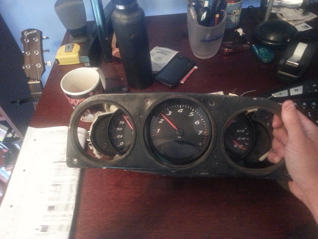 So, onto the fun stuff - electricity! I've spent more time then I care to think about tracing the boxster wiring diagrams and trying to piece together what's needed and what's not. There are several power inputs, (2) which are constant +12V and (3) more which are powered when the key is in the ACC/Drive position in the ignition. Also, there are (2) grounds for the cluster and an additional "ground" for the sender units (fuel, coolant temp, etc). In order to keep strait the mess of wires I manually pinned out and labeled each wire through the connectors. While doing so I found that many of the expected wires/inputs were "missing" from my pins. Some of these are for inputs from the tiptroic transmission which I expect to be missing on a manual cluster. Others though I think are related to the on-board computer option. At this point I'm just worried about basic functionality, so I'm not paying a whole lot of attention to the missing inputs, but they may become important later if the cluster is expecting an input that I'm not delivering. Note my pig-tails are out of a different '97 manual boxster than the gauge cluster, so there could be some miss-match happening if the options on the cars were different. Below there's a picture of my test-rig (basically just a bread board to facilitate quick & easy circuits and and arduino board that I'm using as a signal generator to simulate speedo and tach signals. 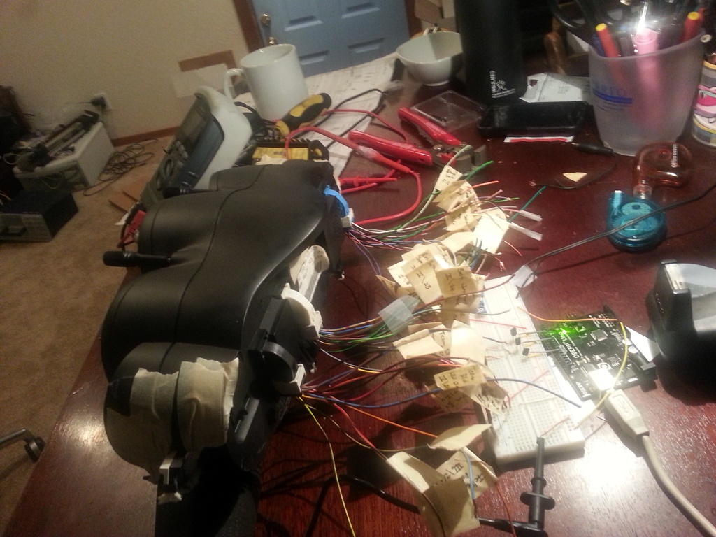 With the gauge cluster powered I then went through at tested the voltage at each (well most anyways) wire to see if any were powered. After doing this I found out something very interesting - most of the indicator lights, the speedo signal, and the tach signal are all powered and expect a ground as their "input". In the case of the speedo and tach they need to be pulled down to ground at a certain frequency, like a flickering light switch, which corresponds to the speed of the car/engine. I'm not sure whether or not this is "normal" for these types of signals, but I was expecting to have to produce a +12V signal to each, not a ground. It actually made it easier in a sense since all I needed to do was use a general purpose transistor as a switch and feed it a PWM signal from the arduino. I addition to those signals, I also got some potentiometers out to simulate the coolant temp and fuel senders. The pic below shows everything running...sort of... 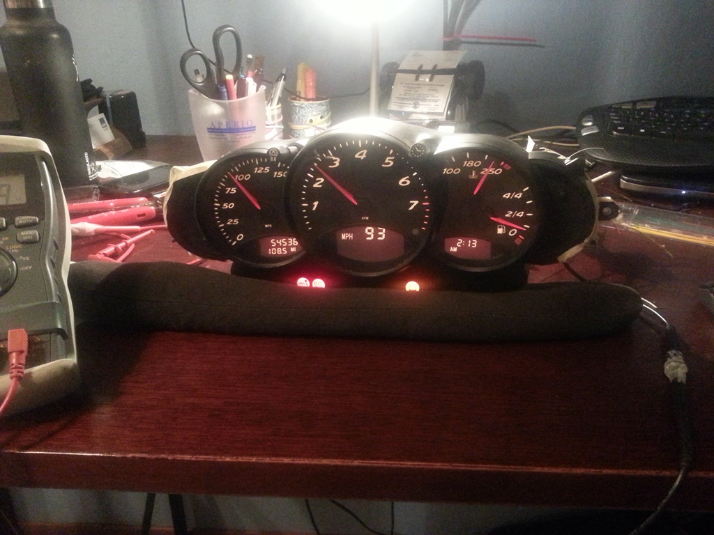 So, the moral of this story is that I've been able to get all the basic functionality working! I've got an Excel spreadsheet I use to calculate at what frequency the PWM signal needs to operate to simulate a specific MPH or RPM. I've also got the coolant temp gauge sender resistance values figured out, the gauge back-lighting/dimming is working, indicator lights are all functional, as well as the turn-signals/high beam indicators, etc.. But....and so far it's been a big pain in the butt....the damn fuel gauge is only sort-of working and represents the final piece to this puzzle. The top 3/4 of the fuel gauge range works flawlessly with a 0 - 400 Ohm potentiomter. However, as soon as you get to ~ 400 Ohms (just less than 1/4 tank) the fuel gauge drops to empty and the low fuel indicator light starts flashing. Doing some reading I found that on the 996 C4's the gas tanks were designed such that a sender wouldn't fit all the way down and then the gauge had to switch over to some sort of internal calculation approach using fuel consumption data from the ECU to estimate fuel tank levels below 12 litres. I didn't get the sense though that this was true of the C2's or the Boxters. Something definitely happens at the 1/4 tank mark where the gauge stops listening to the sender signal. In fact, once it hits that mark I can no longer get the needle to move at all by changing the resistance values. I have to do a full reset on the cluster (un-plug and plug back in) to get it to listen again. I figure it has to be looking for a signal that I'm not giving it right now, and I think I've isolated it to one or two wires: 1) There is a fuel tank status wire going to the DME (ECU) which I thought was an output, but now I'm wondering if it's an input. It has no voltage when the cluster is powered. 2) There is a wire labeled "KVA DME" on the cluster diagrams, but on the DME wiring diagram it's labeled "fuel consumption indicator". I think this one may be the missing piece, but I have no idea what signal it's sending. On the cluster this wire measures +10 V (same as the speedo and tach wires) which makes me think its looking for a similar signal to ground. My current guess it that it will somehow correspond to the fuel injector pulse signal. If anyone has any ideas (or information) on how to get the last quarter of the fuel gauge working I'd LOVE the input. It's the last 10% that takes 90% of the time/effort! |
|
|
|
| purple505uk |
Oct 26 2015, 02:07 PM
Post
#3
|
|
Newbie Group: Members Posts: 1 Joined: 26-October 15 From: ravenshead Member No.: 19,300 Region Association: None |
QUOTE(skeates @ Sep 15 2014, 07:07 PM)  So, until someone tells me this is cluttering up the web I'm going to keep posting my progress (IMG:style_emoticons/default/evilgrin.gif). Made a bit more progress on the boxster gauge cluster this weekend. First things first; even though I'm making a custom dash cap I figured I'd check to see how close this thing fits within the stock set-up. I figured if it fits that would open up a world of opportunities to those wanting to update their gauges, and stick with the Porsche feel without having to make a custom dash. So...I dug out the mounting plate for the stock gauges just to see how close the fit was (see first pic). It's hard to see in the picture, but there are two issues as I can tell which would make it difficult (though not necessarily impossible) to use this with the stock dash cap. 1) The toggles on the top of the cluster (for setting the clock, adjusting brightness, etc.) line up just about perfectly with the two top mounting screw holes. This wouldn't be too hard to work around since you'd be fabricating a custom surround to mount the gauges. At that time just move/make new tabs on the dash frame that line up. Done. 2) The second issue may be somewhat more difficult to work around. Looking at the bottom of the picture you can see that the pod housing the warning lights sticks out slightly below the bottom of the mounting plate. The boxster cluster is just a little bit too tall from what I can tell to fit within the stock dash cap - but it's such a close fit! So close that without an actual dash cap to play with I can't make any final conclusions on the possibility of making this thing fit with the stock dash cap. (if anyone wants to head up to Truckee, Ca with a stock cap to test this out with feel free to swing by (IMG:style_emoticons/default/biggrin.gif) ) So, onto the fun stuff - electricity! I've spent more time then I care to think about tracing the boxster wiring diagrams and trying to piece together what's needed and what's not. There are several power inputs, (2) which are constant +12V and (3) more which are powered when the key is in the ACC/Drive position in the ignition. Also, there are (2) grounds for the cluster and an additional "ground" for the sender units (fuel, coolant temp, etc). In order to keep strait the mess of wires I manually pinned out and labeled each wire through the connectors. While doing so I found that many of the expected wires/inputs were "missing" from my pins. Some of these are for inputs from the tiptroic transmission which I expect to be missing on a manual cluster. Others though I think are related to the on-board computer option. At this point I'm just worried about basic functionality, so I'm not paying a whole lot of attention to the missing inputs, but they may become important later if the cluster is expecting an input that I'm not delivering. Note my pig-tails are out of a different '97 manual boxster than the gauge cluster, so there could be some miss-match happening if the options on the cars were different. Below there's a picture of my test-rig (basically just a bread board to facilitate quick & easy circuits and and arduino board that I'm using as a signal generator to simulate speedo and tach signals. With the gauge cluster powered I then went through at tested the voltage at each (well most anyways) wire to see if any were powered. After doing this I found out something very interesting - most of the indicator lights, the speedo signal, and the tach signal are all powered and expect a ground as their "input". In the case of the speedo and tach they need to be pulled down to ground at a certain frequency, like a flickering light switch, which corresponds to the speed of the car/engine. I'm not sure whether or not this is "normal" for these types of signals, but I was expecting to have to produce a +12V signal to each, not a ground. It actually made it easier in a sense since all I needed to do was use a general purpose transistor as a switch and feed it a PWM signal from the arduino. I addition to those signals, I also got some potentiometers out to simulate the coolant temp and fuel senders. The pic below shows everything running...sort of... So, the moral of this story is that I've been able to get all the basic functionality working! I've got an Excel spreadsheet I use to calculate at what frequency the PWM signal needs to operate to simulate a specific MPH or RPM. I've also got the coolant temp gauge sender resistance values figured out, the gauge back-lighting/dimming is working, indicator lights are all functional, as well as the turn-signals/high beam indicators, etc.. But....and so far it's been a big pain in the butt....the damn fuel gauge is only sort-of working and represents the final piece to this puzzle. The top 3/4 of the fuel gauge range works flawlessly with a 0 - 400 Ohm potentiomter. However, as soon as you get to ~ 400 Ohms (just less than 1/4 tank) the fuel gauge drops to empty and the low fuel indicator light starts flashing. Doing some reading I found that on the 996 C4's the gas tanks were designed such that a sender wouldn't fit all the way down and then the gauge had to switch over to some sort of internal calculation approach using fuel consumption data from the ECU to estimate fuel tank levels below 12 litres. I didn't get the sense though that this was true of the C2's or the Boxters. Something definitely happens at the 1/4 tank mark where the gauge stops listening to the sender signal. In fact, once it hits that mark I can no longer get the needle to move at all by changing the resistance values. I have to do a full reset on the cluster (un-plug and plug back in) to get it to listen again. I figure it has to be looking for a signal that I'm not giving it right now, and I think I've isolated it to one or two wires: 1) There is a fuel tank status wire going to the DME (ECU) which I thought was an output, but now I'm wondering if it's an input. It has no voltage when the cluster is powered. 2) There is a wire labeled "KVA DME" on the cluster diagrams, but on the DME wiring diagram it's labeled "fuel consumption indicator". I think this one may be the missing piece, but I have no idea what signal it's sending. On the cluster this wire measures +10 V (same as the speedo and tach wires) which makes me think its looking for a similar signal to ground. My current guess it that it will somehow correspond to the fuel injector pulse signal. If anyone has any ideas (or information) on how to get the last quarter of the fuel gauge working I'd LOVE the input. It's the last 10% that takes 90% of the time/effort! Great work! Im not the best at electronics and need to power up the lower lcd screens on the same 986 dash can you tell me what voltage i need 12v DC or Ac? , and which colour plugs and which pins do I need to supply this voltage too? Also which ones do i need to ground? Ive tried to work it out from you pic , I cannot tell very well from there, your help is massively appreciated sorry to be a noob!! |
|
|
|
Posts in this topic
 skeates anyone played with boxster gauge cluster? Jul 29 2014, 09:57 PM
 Dave_Darling Depending on the year of Boxster/996, the answer a... Jul 29 2014, 10:14 PM jd74914 I would be highly surprised if the newer stuff did... Jul 30 2014, 06:02 AM stugray If you have the pinouts, please post them.
I have... Jul 30 2014, 07:16 AM
Dave_Darling Depending on the year of Boxster/996, the answer a... Jul 29 2014, 10:14 PM jd74914 I would be highly surprised if the newer stuff did... Jul 30 2014, 06:02 AM stugray If you have the pinouts, please post them.
I have... Jul 30 2014, 07:16 AM
 skeates
If you have the pinouts, please post them.
I hav... Jul 30 2014, 02:48 PM Mike Bellis I'm running a 2000 VW cluster and it does comm... Jul 30 2014, 07:45 AM skeates @ Dave_Darling: I figured anything 2004 or newer w... Jul 30 2014, 02:45 PM jd74914 You are running an Infinity? Which one?
We looke... Jul 31 2014, 07:41 AM skeates
You are running an Infinity? Which one?
We look... Jul 31 2014, 10:19 AM jd74914
You are running an Infinity? Which one?
We loo... Jul 31 2014, 11:23 AM CptTripps Looking forward to seeing progress. Those clusters... Jul 31 2014, 09:14 AM skeates Ok, I bit the bullet and purchased a boxster gauge... Sep 3 2014, 05:44 PM skeates The local hardware store was having a sale on the ... Sep 3 2014, 05:52 PM Dave_Darling One thing I have heard that is important here, if ... Sep 3 2014, 06:14 PM skeates
One thing I have heard that is important here, if... Sep 3 2014, 06:26 PM SirAndy :trophy: That looks better than i thought it wou... Sep 15 2014, 01:22 PM Dr Evil Wow, very nice work :) Sep 17 2014, 07:36 AM Sleepin Sweet!
:popcorn: Sep 17 2014, 08:49 AM boxsterfan Fuchin' awesome!! Sep 17 2014, 09:05 AM Dr Evil Question, just say you have to rely on the engines... Sep 17 2014, 09:22 AM skeates
Question, just say you have to rely on the engine... Sep 17 2014, 06:34 PM timothy_nd28 It would be difficult to defeat the ECU communicat... Sep 17 2014, 09:35 PM skeates
It would be difficult to defeat the ECU communica... Sep 19 2014, 03:43 PM worn
It would be difficult to defeat the ECU communica... Sep 19 2014, 07:13 PM CptTripps :agree: with Andy. This looks a TON better than I ... Sep 18 2014, 08:45 AM Dr Evil Oooooo :)
I like the splicing into the OE motor m... Sep 19 2014, 03:47 PM timothy_nd28 To see how this air core motor is wired internally... Sep 19 2014, 04:07 PM skeates
To see how this air core motor is wired internall... Sep 19 2014, 04:45 PM timothy_nd28 Ok. If you reset the board and have the fuel gauge... Sep 19 2014, 07:53 PM 904svo From the reading you have a stepper motor gas gaug... Sep 19 2014, 08:14 PM skeates
From the reading you have a stepper motor gas gau... Sep 21 2014, 04:09 PM skeates Just finished taking some voltage readings on the ... Sep 19 2014, 11:28 PM timothy_nd28 Is the needle fixed at full level but the voltages... Sep 19 2014, 11:35 PM skeates
Is the needle fixed at full level but the voltage... Sep 20 2014, 12:03 AM Dr Evil While I dig the scholastic effort in figuring out ... Sep 20 2014, 08:04 AM timothy_nd28 No, the voltages do not oscillate as in a motor, b... Sep 20 2014, 08:08 AM skeates
While I dig the scholastic effort in figuring out... Sep 20 2014, 03:55 PM Dr Evil Fascinating. I have never heard of aircore gauges.... Sep 20 2014, 08:15 AM timothy_nd28 In my signature, i did a write up on how to do a t... Sep 20 2014, 08:57 AM Dr Evil Looked at it, bumped it :) Good stuff.
Would the... Sep 20 2014, 11:27 AM timothy_nd28 Absolutely using the original sender, everything w... Sep 20 2014, 11:48 AM timothy_nd28 Absolutely using the original sender, everything w... Sep 20 2014, 11:49 AM Dr Evil Badass! Sep 20 2014, 12:20 PM timothy_nd28 We will help you with the calculations needed for ... Sep 20 2014, 04:49 PM Dr Evil The link on wiki has some suggestions for driver c... Sep 20 2014, 05:20 PM stugray Great work!
On a slightly related note:
Just... Sep 21 2014, 04:36 PM skeates
The link on wiki has some suggestions for driver ... Sep 22 2014, 12:37 AM CptTripps That's just bad ass.... Sep 22 2014, 07:59 AM timothy_nd28 Awesome! Sorry for sending you down a wrong p... Sep 22 2014, 11:20 AM skeates
Awesome! Sorry for sending you down a wrong ... Sep 22 2014, 12:05 PM Scott S Wow. I have never felt dumber. There are some smar... Sep 22 2014, 12:01 PM Philip W.
Wow. I have never felt dumber. There are some sma... Sep 23 2014, 07:31 AM Dr Evil Not that it matters now, since you have been exper... Sep 23 2014, 07:15 AM ruby914 Nice work Skeates!
The Boxter cluster up agai... Sep 23 2014, 10:02 AM skeates
Not that it matters now, since you have been expe... Sep 23 2014, 10:57 AM Dr Evil All of my shit is in boxes in the back of a truck ... Sep 23 2014, 05:52 PM Chris914n6 Cluster fit doesn't look too far off. The loop... Sep 25 2014, 02:27 AM wasz 10 years have gone by - but do you happen to have... Aug 12 2025, 02:29 PM skeates
10 years have gone by - but do you happen to hav... Aug 25 2025, 12:29 PM
skeates
If you have the pinouts, please post them.
I hav... Jul 30 2014, 02:48 PM Mike Bellis I'm running a 2000 VW cluster and it does comm... Jul 30 2014, 07:45 AM skeates @ Dave_Darling: I figured anything 2004 or newer w... Jul 30 2014, 02:45 PM jd74914 You are running an Infinity? Which one?
We looke... Jul 31 2014, 07:41 AM skeates
You are running an Infinity? Which one?
We look... Jul 31 2014, 10:19 AM jd74914
You are running an Infinity? Which one?
We loo... Jul 31 2014, 11:23 AM CptTripps Looking forward to seeing progress. Those clusters... Jul 31 2014, 09:14 AM skeates Ok, I bit the bullet and purchased a boxster gauge... Sep 3 2014, 05:44 PM skeates The local hardware store was having a sale on the ... Sep 3 2014, 05:52 PM Dave_Darling One thing I have heard that is important here, if ... Sep 3 2014, 06:14 PM skeates
One thing I have heard that is important here, if... Sep 3 2014, 06:26 PM SirAndy :trophy: That looks better than i thought it wou... Sep 15 2014, 01:22 PM Dr Evil Wow, very nice work :) Sep 17 2014, 07:36 AM Sleepin Sweet!
:popcorn: Sep 17 2014, 08:49 AM boxsterfan Fuchin' awesome!! Sep 17 2014, 09:05 AM Dr Evil Question, just say you have to rely on the engines... Sep 17 2014, 09:22 AM skeates
Question, just say you have to rely on the engine... Sep 17 2014, 06:34 PM timothy_nd28 It would be difficult to defeat the ECU communicat... Sep 17 2014, 09:35 PM skeates
It would be difficult to defeat the ECU communica... Sep 19 2014, 03:43 PM worn
It would be difficult to defeat the ECU communica... Sep 19 2014, 07:13 PM CptTripps :agree: with Andy. This looks a TON better than I ... Sep 18 2014, 08:45 AM Dr Evil Oooooo :)
I like the splicing into the OE motor m... Sep 19 2014, 03:47 PM timothy_nd28 To see how this air core motor is wired internally... Sep 19 2014, 04:07 PM skeates
To see how this air core motor is wired internall... Sep 19 2014, 04:45 PM timothy_nd28 Ok. If you reset the board and have the fuel gauge... Sep 19 2014, 07:53 PM 904svo From the reading you have a stepper motor gas gaug... Sep 19 2014, 08:14 PM skeates
From the reading you have a stepper motor gas gau... Sep 21 2014, 04:09 PM skeates Just finished taking some voltage readings on the ... Sep 19 2014, 11:28 PM timothy_nd28 Is the needle fixed at full level but the voltages... Sep 19 2014, 11:35 PM skeates
Is the needle fixed at full level but the voltage... Sep 20 2014, 12:03 AM Dr Evil While I dig the scholastic effort in figuring out ... Sep 20 2014, 08:04 AM timothy_nd28 No, the voltages do not oscillate as in a motor, b... Sep 20 2014, 08:08 AM skeates
While I dig the scholastic effort in figuring out... Sep 20 2014, 03:55 PM Dr Evil Fascinating. I have never heard of aircore gauges.... Sep 20 2014, 08:15 AM timothy_nd28 In my signature, i did a write up on how to do a t... Sep 20 2014, 08:57 AM Dr Evil Looked at it, bumped it :) Good stuff.
Would the... Sep 20 2014, 11:27 AM timothy_nd28 Absolutely using the original sender, everything w... Sep 20 2014, 11:48 AM timothy_nd28 Absolutely using the original sender, everything w... Sep 20 2014, 11:49 AM Dr Evil Badass! Sep 20 2014, 12:20 PM timothy_nd28 We will help you with the calculations needed for ... Sep 20 2014, 04:49 PM Dr Evil The link on wiki has some suggestions for driver c... Sep 20 2014, 05:20 PM stugray Great work!
On a slightly related note:
Just... Sep 21 2014, 04:36 PM skeates
The link on wiki has some suggestions for driver ... Sep 22 2014, 12:37 AM CptTripps That's just bad ass.... Sep 22 2014, 07:59 AM timothy_nd28 Awesome! Sorry for sending you down a wrong p... Sep 22 2014, 11:20 AM skeates
Awesome! Sorry for sending you down a wrong ... Sep 22 2014, 12:05 PM Scott S Wow. I have never felt dumber. There are some smar... Sep 22 2014, 12:01 PM Philip W.
Wow. I have never felt dumber. There are some sma... Sep 23 2014, 07:31 AM Dr Evil Not that it matters now, since you have been exper... Sep 23 2014, 07:15 AM ruby914 Nice work Skeates!
The Boxter cluster up agai... Sep 23 2014, 10:02 AM skeates
Not that it matters now, since you have been expe... Sep 23 2014, 10:57 AM Dr Evil All of my shit is in boxes in the back of a truck ... Sep 23 2014, 05:52 PM Chris914n6 Cluster fit doesn't look too far off. The loop... Sep 25 2014, 02:27 AM wasz 10 years have gone by - but do you happen to have... Aug 12 2025, 02:29 PM skeates
10 years have gone by - but do you happen to hav... Aug 25 2025, 12:29 PM |
1 User(s) are reading this topic (1 Guests and 0 Anonymous Users)
0 Members:

|
Lo-Fi Version | Time is now: 25th March 2026 - 09:37 AM |
Invision Power Board
v9.1.4 © 2026 IPS, Inc.