|
|

|
Porsche, and the Porsche crest are registered trademarks of Dr. Ing. h.c. F. Porsche AG.
This site is not affiliated with Porsche in any way. Its only purpose is to provide an online forum for car enthusiasts. All other trademarks are property of their respective owners. |
|
|
| Mblizzard |
 Nov 16 2017, 02:03 PM Nov 16 2017, 02:03 PM
Post
#1
|
|
Advanced Member     Group: Members Posts: 3,033 Joined: 28-January 13 From: Knoxville Tn Member No.: 15,438 Region Association: South East States |
I have converted my 2.0 to a 2056 and added Micro Squirt fuel injection.
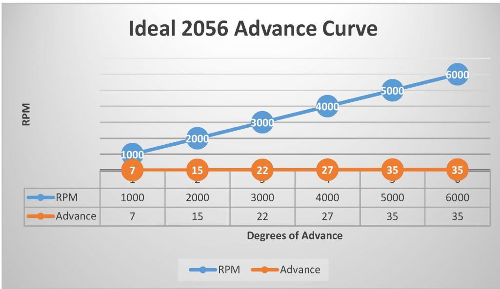
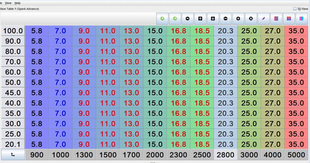
Ever since I did the 2056 conversion I have seen higher than norm cylinder head temperatures. In fact I cracked a set of heads from getting them too hot. I played around with the timing with in the suggested 2.0 limits of around 27 degrees. but was really never able to influence the CHTs that much with changes in the timing. Adding more fuel at the right times with the Micro Squirt certainly allowed me to control the CHT much better but I always felt it was still getting too high. Then I ran across this.  This is certainly a lot more advance than I ever added to the engine. So based on that I revised my timing table to:  Just love how easy it is to make changes with Micro Squirt. So I am looking to see what the thoughts are on 35 degrees of advance and what impacts it may have on CHT. I am going to load this and test tomorrow. |
  |
Replies
| Mark Henry |
 Nov 24 2017, 03:35 PM Nov 24 2017, 03:35 PM
Post
#2
|
|
that's what I do!                Group: Members Posts: 20,065 Joined: 27-December 02 From: Port Hope, Ontario Member No.: 26 Region Association: Canada |
I got to admit looking at those tables is so confusing, the main reason I've never embraced MS or other data overload systems.
It's a fricken timing curve, not rocket science! My SDS has one value per 250 rpm, that's it. Same could be said about a mechanical dizzy, sure springs but it's a simple curve. I agree with Jake and Mark, idle too low I run 10* and 30*+ is too much advance on a T4, I run 28*. If anything I'd consider retarding the timing a bit as I approached 6000 rpm. One of my tricks when tuning is I have a highway close by that has a long (10km) steady uphill grade and it's divided by a concrete barrier. When in the passing lane you are about 24" from the barrier and the sound bounces so you can really hear the engine mechanicly. I've tested 1.8, 2.0, 2056, 2270, and my 2600 T4's any time I push it to 30* I can hear the ping. I can also see head temps going up. Ping is about the equivalent of hitting your piston top with a ball-peen hammer. Sooner or later it will kill your engine. The chart above "Ideal 2056 Adavance Curve" that might work on a WC engine but I'd never consider it on an aircooled T4. |
| JamesM |
 Dec 3 2017, 04:41 AM Dec 3 2017, 04:41 AM
Post
#3
|
|
Senior Member    Group: Members Posts: 1,992 Joined: 6-April 06 From: Kearns, UT Member No.: 5,834 Region Association: Intermountain Region |
I got to admit looking at those tables is so confusing, the main reason I've never embraced MS or other data overload systems. It's a fricken timing curve, not rocket science! Watching a three dimensional system operate in real time helps a lot in understanding how it works and in reality it is not much more than a simple timing curve once you know how to read the table. Its really just 10 simple timing curves stacked on top of each other. Take a single horizontal line of the table and that is basically what you have with SDS, a timing setting where the only variable is RPM ( X RPM = Z degrees advance) Like a distributor that only has centrifugal advance. Setting all the horizontal lines up the same produces a table that works exactly like SDS works. The Y axis of the table represents engine load. Depending on how you have the system configured this is usually determined from manifold vacuum but could also be throttle position. So basically every horizontal line is its own independent timing curve and which one is in use at any given time depends on how much load the engine is currently under (or at what position the throttle is). So the top line is basically the ignition curve that is used at wide open throttle, and the bottom line is the timing curve used when the engine is closed throttle under deceleration and everything in between is everything in between, timing curve for 60% throttle, 70% throttle etc. Its sort of like adding vacuum advance and retard cans to a distributor, but magic ones that are able to defy the laws of physics that apply to a vacuum canister in order to provide exactly what you want at all time. Obviously having load dependent timing curves is not necessary for an engine but it does allow you to optimize for all running conditions and do some cool stuff, tricks that you couldn't otherwise do. It can be used to improve drive ability, gas mileage, emissions etc without impacting your WOT power. Fully optimizing a tune to this extent though would require tools not readily available to a home mechanic which is why i question a lot of peoples tables that look like they have been. The table I posted is pretty simple as it is basically the same curve across all loads, the only change i made from there was to not have the timing advance as quickly in the low load/idle area of the map in order to help stabilize the idle but still immediately ramp up the advance as soon as you get on the gas. |
Posts in this topic
 Mblizzard 2056 Timing Nov 16 2017, 02:03 PM
 yeahmag I run a Mallory with the recommended "grey/gr... Nov 17 2017, 12:50 PM
 JamesM Mike,
Is there specific RPM/Load point on your... Nov 17 2017, 02:56 PM

 Mblizzard
Mike,
Is there specific RPM/Load point on you... Nov 21 2017, 03:40 PM

 Vacca Rabite
I got no attachment to this table and like you ... Nov 22 2017, 10:57 AM

 Mblizzard
I got no attachment to this table and like you... Nov 22 2017, 11:13 AM
 JamesM This is the table I run on my 2056. It gives very... Nov 17 2017, 03:09 PM
 Mblizzard Source of suggested advanced curve.
http://www.vo... Nov 22 2017, 10:20 AM
 McMark I would ensure the timing accuracy -- make sure yo... Nov 22 2017, 12:54 PM

 Mblizzard
I would ensure the timing accuracy -- make sure y... Nov 22 2017, 03:21 PM
 Jake Raby Every combination will optimize with a different i... Nov 22 2017, 10:13 PM
 Mark Henry :agree:
I run 28* total on my SDS efi crankfire ... Nov 24 2017, 10:09 AM
 falcor75
Heres my ign table, 2256cc, web 86b/c 10:1 comp... Nov 24 2017, 01:42 PM

 Mblizzard
I got to admit looking at those tables is so con... Dec 3 2017, 06:37 AM
 rhodyguy You can dial back the total advance with your phon... Nov 25 2017, 01:18 PM

 Mblizzard
You can dial back the total advance with your pho... Nov 25 2017, 05:07 PM
 McMark Hey Mike, do you have an IR thermometer? The gun... Nov 26 2017, 07:27 AM
 Mblizzard
Hey Mike, do you have an IR thermometer? The gu... Dec 3 2017, 06:32 AM
  |
11 User(s) are reading this topic (11 Guests and 0 Anonymous Users)
0 Members:

|
Lo-Fi Version | Time is now: 25th November 2024 - 09:45 AM |
Invision Power Board
v9.1.4 © 2024 IPS, Inc.


