|
|

|
Porsche, and the Porsche crest are registered trademarks of Dr. Ing. h.c. F. Porsche AG.
This site is not affiliated with Porsche in any way. Its only purpose is to provide an online forum for car enthusiasts. All other trademarks are property of their respective owners. |
|
|
| jjs3rd914 |
 May 20 2018, 01:01 PM May 20 2018, 01:01 PM
Post
#1
|
|
Member   Group: Members Posts: 124 Joined: 8-August 04 From: Sarasota, FL Member No.: 2,476 |
Curiosity question.
When type 4 heads are to be fly-cut for increased compression, where/what plane does the machinist set up on. Videos seem to show the setup is the head being clamped on the valve cover surface to the mill table..... So is that surface suppose to be parallel to the chamber sealing surface?? If so what is acceptable variance across the sealing circle to the valve cover surface. We have measured our new set of 2L head castings and there is up to a .002" variance from on side of the sealing surface to the other with respect to the valve cover surface. So in this case the sealing surface is not parallel (in the same plane) to the valve cover surface? But does is matter as long as the sealing surface itself is flat all the way around to the to the cylinder top and both chambers on each head are in the same plane? Do these heads need touched up? What am I missing here?? Thanks jjs3rd914 |
  |
Replies
| jjs3rd914 |
 May 20 2018, 03:48 PM May 20 2018, 03:48 PM
Post
#2
|
|
Member   Group: Members Posts: 124 Joined: 8-August 04 From: Sarasota, FL Member No.: 2,476 |
Interesting discussion. I am learning.
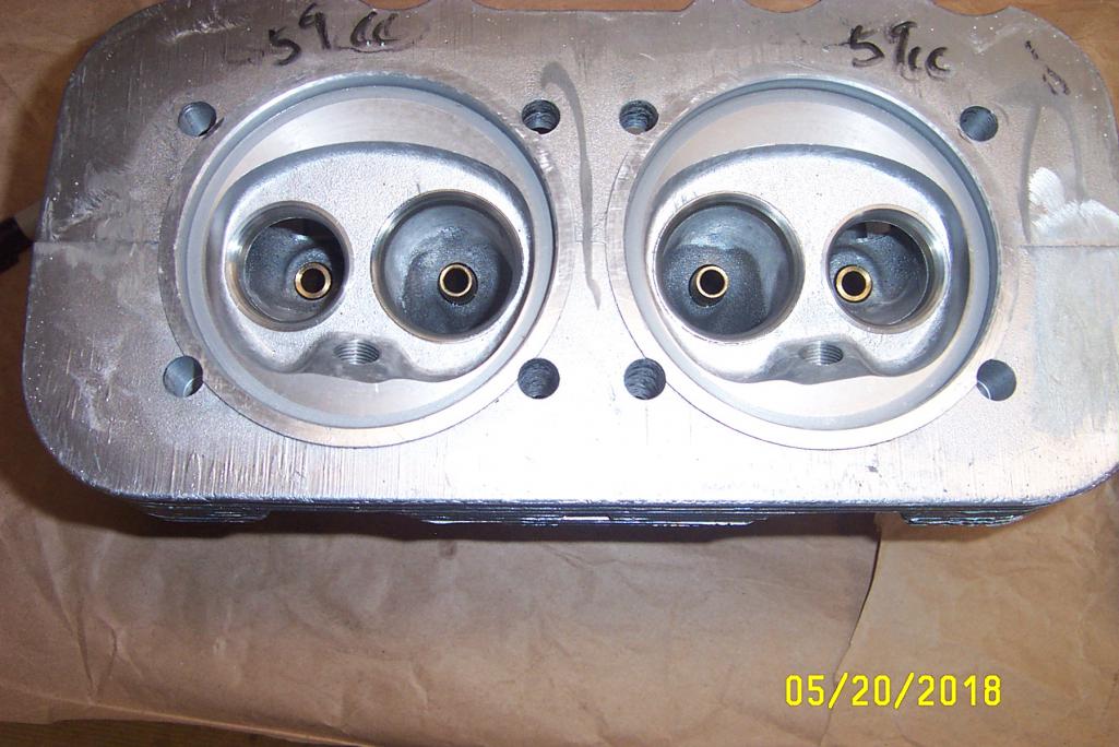
I agree with Worn " if it isn’t as long as the surfaces sealing against the jugs are flat and on the same plane. What is the issue?" The question is to what does one reference to (measure from) to verify that the two adjacent sealing surfaces are indeed in the same plane.? The only other surface besides the valve cover plane could be the machined surface sitting above the counter bore in the head. What is the purpose of this machined surface? See pic. Anyhow here is some data. Using the valve cover plane surface as reference. Sealing surface on chamber #1 on the right in pic is the same relative measurement at 6 and 12 o'clock. But at 9 o'clock it is is .0015" higher to that of 6 and 12 o'clock, and at 3 o'clock .001" lower. Chamber #2, at 6 is .0015 higher (referencing back to dimension on # 1 at 6 and 12), at 9 o'clock is .0005 lower, at 12 .0005 lower, and at 3 .001 higher. So clearly the two planes are not parallel and are not at the exactly same height at least "relative to the valve cover surface" Maybe this is acceptable. I do not know. As I said I am trying to understand and learn. Yes Mark Henry my case registers are "collapsed" and case will be machined to even them out. I had all the new cylinders all machined to exactly the same height. So we should be starting with straight parallel registers, then even cylinders, and hopefully even heads. Thanks all jjs3rd914  |
Posts in this topic
 jjs3rd914 Where/What is reference plane- when flycutting heads? May 20 2018, 01:01 PM
 Mark Henry Yes, OK, maybe, nothing. :D
.002 is a hair, fl... May 20 2018, 02:16 PM
 Mark Henry Also to do it right machine the case decks flat.
... May 20 2018, 02:21 PM

 worn
Also to do it right machine the case decks flat. ... May 20 2018, 02:44 PM


 Mark Henry
Also to do it right machine the case decks flat.... May 20 2018, 02:52 PM

 wndsrfr Hmmmm....maybe clean up the one with the least var... May 21 2018, 05:30 AM
 Mark Henry You can obsess over .0001" but it quickly bec... May 21 2018, 09:05 AM
  |
1 User(s) are reading this topic (1 Guests and 0 Anonymous Users)
0 Members:

|
Lo-Fi Version | Time is now: 24th December 2025 - 05:45 AM |
Invision Power Board
v9.1.4 © 2025 IPS, Inc.


