|
|
|
Porsche, and the Porsche crest are registered trademarks of Dr. Ing. h.c. F. Porsche AG.
This site is not affiliated with Porsche in any way. Its only purpose is to provide an online forum for car enthusiasts. All other trademarks are property of their respective owners. |
|
|


| Tom |
 May 3 2014, 01:30 PM May 3 2014, 01:30 PM
Post
#1
|
|
Advanced Member  Group: Members Posts: 2,139 Joined: 21-August 05 From: Port Orchard, WA 98367 Member No.: 4,626 Region Association: None |
After reading many accounts of how this circuit works, I felt compelled to investigate further as I did not understand how two positives would cause a light to operate. They won't. One must be somewhat negative to complete the circuit. Internet searches turned up the same basic explanation, still was not buying it. I think it was being oversimplified.
This is how I think the alt light works: When the key is on and engine not running, there is 12 volts + at the alt light power side coming from the fused side of fuse #9. The other side goes to a junction on the relay board with D+. With the key to off and a meter connected between D+ and ground at the relay board, the reading is 12 ohms. As soon as the key is turned to on, the reading jumps to 12.5 meg ohms and the light comes on. If the wire for D+ to the alt is removed, the reading stays the same and the light stays on. Removing the VR caused the reading to jump to infinity and the light goes out. For the light to work, there has to be power to one side of the light and some resistance reading to ground for the other. Looking at the wiring diagram, one can follow the blue wire to the junction at the relay board at D+, then up thru the VR to a set of relay contacts, then down thru a ( resistor ?, not sure) and then down to the DF connection and on to the rotor where the current will produce a magnetic field. After the rotor, it goes to ground. When the alt spins enough RPM's, a voltage is produced and fed back to the VR, causing the relay to open and removes the ground path for the alt light. I could be entirely wrong here, but this is what I see and my readings more or less confirm it. If you see an error in my thinking, please post and let me know. Thanks, Tom Attached thumbnail(s) 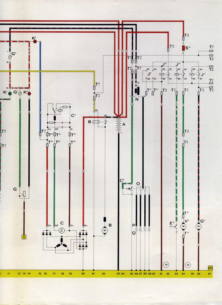
|
   |

 
|
  |
Replies
| mikesmith |
Jul 28 2019, 01:24 PM
Post
#2
|
|
Member Group: Members Posts: 202 Joined: 5-September 13 From: SF Member No.: 16,354 Region Association: Northern California |
QUOTE(Tom @ May 3 2014, 12:30 PM)  After reading many accounts of how this circuit works, I felt compelled to investigate further as I did not understand how two positives would cause a light to operate. They won't. One must be somewhat negative to complete the circuit. Internet searches turned up the same basic explanation, still was not buying it. I think it was being oversimplified. The functioning of the regulator is a bit sneaky and not necessarily obvious (though honestly you can say this of a lot of pieces of heavily cost-optimised technology). 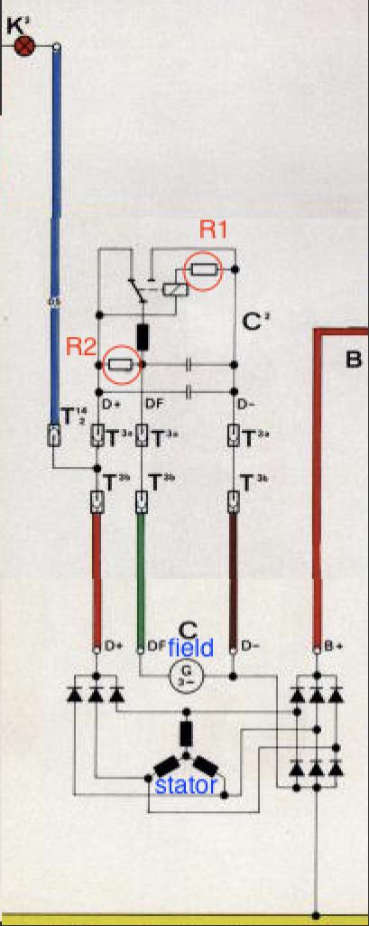 Things to know: - The alternator will only produce an output when current is already flowing through the field coil (marked G). This is the coil that spins when the alternator input shaft is turned by the engine. - There are a couple of capacitors (close vertical lines) in the regulator drawing; I've covered some of their functions here but almost certainly not all of them. - I only marked two of the resistors in the drawing, there's another that's blacked in - being blacked in almost certainly means something, but it's not clear what. - Current takes time to start up / slow down, especially when it's flowing through coils like the field or stator coils in the alternator. - It takes more current flowing through the coil to turn a relay on than it does to keep it on (so the 'turn off' current is lower than the 'turn on' current). - Like most folks I'll use positive-to-negative when describing current flow; don't be upset that electrons actually move the the other way. 8) When the engine is off, and immediately after it's started, current flows from the battery, through fuse #9, through the alternator warning lamp (K2), through the D+ terminal on the regulator, through the relay in the regulator and out the DF terminal, to the DF terminal on the alternator, then out the alternator ground back to the battery (current always flows in circles). This provides the necessary field coil current to bootstrap the alternator. Once the engine has started the voltage across the stator coils begins to rise. Current will start to flow out the D+ terminal once the voltage rises above a certain point (tough to calculate due to the way the field coil behaves, but probably a few volts), and then out the B+ terminal once it rises above the current battery voltage. While current is flowing out both terminals the voltage on each terminal will be nearly the same (since in both cases the current's coming from the stator coils). B+ will never fall below battery voltage; D+ will never go (much) higher than battery voltage / B+, but may be quite a bit lower at times. As B+ is connected to the battery, and thus to the other side of the warning lamp (K2) this means there will be no current flow through the lamp and it will go out once D+ reaches battery voltage (no voltage difference -> no current flow). The voltage on B+ and D+ will continue to rise (assuming the alternator is spinning fast enough) as the battery charges. As the voltage on the D+ terminal continues to rise, the current flowing through the regulator relay coil and resistor R1 (circled in red) also rises. Eventually this current is sufficient to energize the relay and it switches, disconnecting the field coil (and in fact shorting it to D- to ensure that no leakage current continues to energize it). The upper of the two capacitors in the diagram helps prevent damage to the relay contacts during this switching operation. Removal of the field coil current causes the stator coil to stop generating (this isn't instantaneous; the field coil current falls, the magnetic field starts to collapse, the stator induced current falls...). As the stator voltage falls the current out the B+ terminal falls, reducing charge current to the battery / rest of the vehicle. At the same time the voltage on the D+ terminal and thus the current through the relay coil / R1 also falls; some current flows via K2 but this is insufficient to keep the relay energized. This causes the relay to switch back, returning the alternator / regulator to a state similar to the bootstrap state. At this point, there are several sources of current for the field coil; the bootstrap path through K2, the residual charge in the lower of the two capacitors, and the the stator via D+ and R2; one or more of these (probably all three contribute) cause the field coil current to rise and the cycle repeats. The on/off process repeats very quickly; it can be several hundred times a second. During the off phase some current may flow through K2, but the average current will be low enough that the lamp won't light. The duty cycle (ratio of on time to off time) will vary based on the load on the system; more load will cause the B+ / D+ voltage to rise more slowly, delaying the time until the relay switches. With less load, it will rise more quickly. The time the charge circuit spends off will (tend to) be more constant, as it's related to the value of the lower capacitor and the characteristics of the relay coil, which don't vary with load. HTH, and apologies for any errors or confusion this might cause. |
|
|
|
Posts in this topic
Tom How alternator light works May 3 2014, 01:30 PM bulitt I recall you need a light or resistor to "exc... May 3 2014, 01:47 PM toolguy Light comes on when the alternator out voltage on ... May 3 2014, 02:38 PM Spoke
I could be entirely wrong here, but this is what ... May 3 2014, 03:47 PM Dave_Darling A couple of minor misconceptions in the OP:
The l... May 3 2014, 04:24 PM
bulitt I recall you need a light or resistor to "exc... May 3 2014, 01:47 PM toolguy Light comes on when the alternator out voltage on ... May 3 2014, 02:38 PM Spoke
I could be entirely wrong here, but this is what ... May 3 2014, 03:47 PM Dave_Darling A couple of minor misconceptions in the OP:
The l... May 3 2014, 04:24 PM
 type47
... and there are other failure modes that will m... Aug 26 2014, 06:41 AM Dave_Darling
Could you expand on this?
If some of your altern... Aug 26 2014, 09:23 AM 76-914 :wacko: Wow! I'm still a little dazed but ... May 3 2014, 04:50 PM worn
After reading many accounts of how this circuit w... May 3 2014, 07:47 PM stugray Every one else covered the basics very well above.... May 3 2014, 09:21 PM Tom stugray,
OMG, you are so right! I don... May 4 2014, 12:44 PM ThePaintedMan Check the voltage regulator. Aug 26 2014, 07:46 AM stugray There is a test where you unplug the VR and connec... Aug 26 2014, 08:05 AM type47 The alt I removed this morning and tested good has... Aug 26 2014, 10:33 AM type47 So, there is no joy in Mudville, the alt light is ... Sep 5 2014, 09:21 AM Spoke Alternator testing good may not completely test al... Sep 5 2014, 10:27 AM type47
Alternator testing good may not completely test a... Sep 5 2014, 03:21 PM Spoke Remove the gauge bucket with the GEN light. Start ... Sep 5 2014, 04:02 PM type47
...what is the battery voltage when the car is id... Sep 9 2014, 04:57 PM The Cabinetmaker Last time I saw a bad vr I replaced it with the so... Sep 5 2014, 04:10 PM type47
Last time I saw a bad vr I replaced it with the s... Sep 5 2014, 05:29 PM Dave_Darling If that's the voltage across the battery posts... Sep 9 2014, 11:55 PM GregAmy So instead of starting a new thread, I'm going... Jul 27 2019, 09:25 AM Spoke I would take a guess at about 200 ohm should do. B... Jul 27 2019, 10:14 AM GregAmy That's some beautiful stuff right there (along... Jul 29 2019, 02:51 PM Spoke
That's some beautiful stuff right there (alon... Jul 29 2019, 08:24 PM mikesmith
- After posting, I took the racer out for a spin ... Jul 29 2019, 03:42 PM GregAmy Your description just begs more questions, sadly. ... Jul 29 2019, 07:56 PM 930cabman Another old, old thread
Generator light will not ... Jul 10 2024, 04:52 PM Spoke
Another old, old thread
Generator light will not... Jul 11 2024, 11:15 PM 930cabman
[quote name='930cabman' post='3155854' date='Jul ... Jul 12 2024, 04:59 AM Spoke
Thank you Spoke, this issue is with a recent /6 c... Jul 12 2024, 07:58 AM Lucky9146 Glad this thread got bumped, the diagrams and info... Jul 11 2024, 11:17 PM ClayPerrine This sounds like an issue with bad grounds.
Was... Jul 12 2024, 05:32 AM 930cabman
This sounds like an issue with bad grounds.
Wa... Jul 12 2024, 05:38 AM 87m491 Not for nothing, but unless I missed it you have n... Jul 12 2024, 06:30 AM technicalninja Spoke and Dave Darling have their shit together... Jul 12 2024, 08:18 AM 930cabman Once again, the 914 World Team has killed it.
Now... Jul 12 2024, 09:13 AM 930cabman Excited
Still having an issue, but seems as thoug... Jul 14 2024, 04:32 PM Superhawk996
Excited
Still having an issue, but seems as thou... Jul 14 2024, 05:44 PM 930cabman
[quote name='930cabman' post='3156695' date='Jul ... Jul 15 2024, 11:29 AM Superhawk996
When you say blue wire has nothing on it is th... Jul 15 2024, 12:57 PM 930cabman
[quote name='930cabman' post='3156853' date='Jul ... Jul 15 2024, 01:00 PM Superhawk996
maybe the bulb wattage is not allowing the alte... Jul 15 2024, 01:14 PM 930cabman
maybe the bulb wattage is not allowing the alt... Jul 15 2024, 01:20 PM Superhawk996
After a few blips she starts charging and stays... Jul 15 2024, 01:33 PM Spoke
Excited
Still having an issue, but seems as thou... Jul 15 2024, 08:23 AM 930cabman
Excited
Still having an issue, but seems as tho... Jul 15 2024, 09:21 AM 930cabman Got it, mostly. As you can imagine this has been d... Jul 15 2024, 04:25 PM Superhawk996
Got it, mostly. As you can imagine this has been ... Jul 15 2024, 05:02 PM 930cabman
Got it, mostly. As you can imagine this has been... Jul 15 2024, 06:19 PM
type47
... and there are other failure modes that will m... Aug 26 2014, 06:41 AM Dave_Darling
Could you expand on this?
If some of your altern... Aug 26 2014, 09:23 AM 76-914 :wacko: Wow! I'm still a little dazed but ... May 3 2014, 04:50 PM worn
After reading many accounts of how this circuit w... May 3 2014, 07:47 PM stugray Every one else covered the basics very well above.... May 3 2014, 09:21 PM Tom stugray,
OMG, you are so right! I don... May 4 2014, 12:44 PM ThePaintedMan Check the voltage regulator. Aug 26 2014, 07:46 AM stugray There is a test where you unplug the VR and connec... Aug 26 2014, 08:05 AM type47 The alt I removed this morning and tested good has... Aug 26 2014, 10:33 AM type47 So, there is no joy in Mudville, the alt light is ... Sep 5 2014, 09:21 AM Spoke Alternator testing good may not completely test al... Sep 5 2014, 10:27 AM type47
Alternator testing good may not completely test a... Sep 5 2014, 03:21 PM Spoke Remove the gauge bucket with the GEN light. Start ... Sep 5 2014, 04:02 PM type47
...what is the battery voltage when the car is id... Sep 9 2014, 04:57 PM The Cabinetmaker Last time I saw a bad vr I replaced it with the so... Sep 5 2014, 04:10 PM type47
Last time I saw a bad vr I replaced it with the s... Sep 5 2014, 05:29 PM Dave_Darling If that's the voltage across the battery posts... Sep 9 2014, 11:55 PM GregAmy So instead of starting a new thread, I'm going... Jul 27 2019, 09:25 AM Spoke I would take a guess at about 200 ohm should do. B... Jul 27 2019, 10:14 AM GregAmy That's some beautiful stuff right there (along... Jul 29 2019, 02:51 PM Spoke
That's some beautiful stuff right there (alon... Jul 29 2019, 08:24 PM mikesmith
- After posting, I took the racer out for a spin ... Jul 29 2019, 03:42 PM GregAmy Your description just begs more questions, sadly. ... Jul 29 2019, 07:56 PM 930cabman Another old, old thread
Generator light will not ... Jul 10 2024, 04:52 PM Spoke
Another old, old thread
Generator light will not... Jul 11 2024, 11:15 PM 930cabman
[quote name='930cabman' post='3155854' date='Jul ... Jul 12 2024, 04:59 AM Spoke
Thank you Spoke, this issue is with a recent /6 c... Jul 12 2024, 07:58 AM Lucky9146 Glad this thread got bumped, the diagrams and info... Jul 11 2024, 11:17 PM ClayPerrine This sounds like an issue with bad grounds.
Was... Jul 12 2024, 05:32 AM 930cabman
This sounds like an issue with bad grounds.
Wa... Jul 12 2024, 05:38 AM 87m491 Not for nothing, but unless I missed it you have n... Jul 12 2024, 06:30 AM technicalninja Spoke and Dave Darling have their shit together... Jul 12 2024, 08:18 AM 930cabman Once again, the 914 World Team has killed it.
Now... Jul 12 2024, 09:13 AM 930cabman Excited
Still having an issue, but seems as thoug... Jul 14 2024, 04:32 PM Superhawk996
Excited
Still having an issue, but seems as thou... Jul 14 2024, 05:44 PM 930cabman
[quote name='930cabman' post='3156695' date='Jul ... Jul 15 2024, 11:29 AM Superhawk996
When you say blue wire has nothing on it is th... Jul 15 2024, 12:57 PM 930cabman
[quote name='930cabman' post='3156853' date='Jul ... Jul 15 2024, 01:00 PM Superhawk996
maybe the bulb wattage is not allowing the alte... Jul 15 2024, 01:14 PM 930cabman
maybe the bulb wattage is not allowing the alt... Jul 15 2024, 01:20 PM Superhawk996
After a few blips she starts charging and stays... Jul 15 2024, 01:33 PM Spoke
Excited
Still having an issue, but seems as thou... Jul 15 2024, 08:23 AM 930cabman
Excited
Still having an issue, but seems as tho... Jul 15 2024, 09:21 AM 930cabman Got it, mostly. As you can imagine this has been d... Jul 15 2024, 04:25 PM Superhawk996
Got it, mostly. As you can imagine this has been ... Jul 15 2024, 05:02 PM 930cabman
Got it, mostly. As you can imagine this has been... Jul 15 2024, 06:19 PM |
18 User(s) are reading this topic (18 Guests and 0 Anonymous Users)
0 Members:

|
Lo-Fi Version | Time is now: 18th September 2024 - 07:20 PM |
Invision Power Board
v9.1.4 © 2024 IPS, Inc.