|
|

|
Porsche, and the Porsche crest are registered trademarks of Dr. Ing. h.c. F. Porsche AG.
This site is not affiliated with Porsche in any way. Its only purpose is to provide an online forum for car enthusiasts. All other trademarks are property of their respective owners. |
|
|
| Montreal914 |
 Dec 22 2019, 01:53 PM Dec 22 2019, 01:53 PM
Post
#1
|
|
Senior Member    Group: Members Posts: 1,699 Joined: 8-August 10 From: Claremont, CA Member No.: 12,023 Region Association: Southern California 
|
After reading and reading some more, I finally decided a few months ago to challenge myself with a Microsquirt conversion. Many members here were very inspirational. (IMG:style_emoticons/default/smilie_pokal.gif) I want to thank the ones who have shared their builds and issues as they are very helpful. I hope my build can contribute to others and add to this wealth of information. I'm also aware that I might run into issues but that is part of the process.
First, a little background. A few years back I rebuilt my 2.0 due to a spun rod bearing on my last run of my first DE event with POC at Streets of Willows. (IMG:style_emoticons/default/driving.gif) While this was an unpleasant outcome, the day still remains a fantastic moment with my 914. (IMG:style_emoticons/default/smile.gif) I did the rebuild myself with all of the valuable information here. (IMG:style_emoticons/default/first.gif) I like to think that I did things right and the outcome is a fun 2056 with mild cam, D-Jet oblige, that I have enjoyed commuting with for many years and took along the coast all the way to Monterey four times, two of which were to attend the amazing Rennsport Reunion V and VI. (IMG:style_emoticons/default/pray.gif) One of the reasons I want to upgrade to a modern FI system is to be able to better tune the engine which is limited on the D-Jet, especially when engine displacement is increased as we know. This is the first step in my ultimate build which would be a 78x96 stroker engine. But that will be later. (IMG:style_emoticons/default/drooley.gif) So here we go! I bought my Microsquirt and crank trigger sensor sensor setup from Mario at the Dubshop. I like the way the trigger is engineered and it allows the installation of remote oil plumbing (full-er flow setup). Being on a very tight budget (I know this doesn't rimes with 914 anymore) I bought all my new individual components from ebay with matching pigtail connectors to build my own harness. VW waste spark coil pack GM 1 bar MAP sensor Hyundai (and others) TPS BMW ICV BMW air cooled motorcycle CHT sensor (used). Same M10 thread as the D-Jet CHT. I will be reusing: Stock green injectors, with additional resistors Stock IAT sensor I also bought new connectors and crimp terminals and boots for all reused stock components. To begin the build, I elected to prepare a development harness with extra wire length and build a bread board setup. This will allow me to make sure that all components are functioning. Once the engine is running, I will rebuild the harness with the proper wire length and sleeves to ensure a clean and reliable installation. Enough writing... On with what people want! Pictures (IMG:style_emoticons/default/biggrin.gif) Bread Board setup: 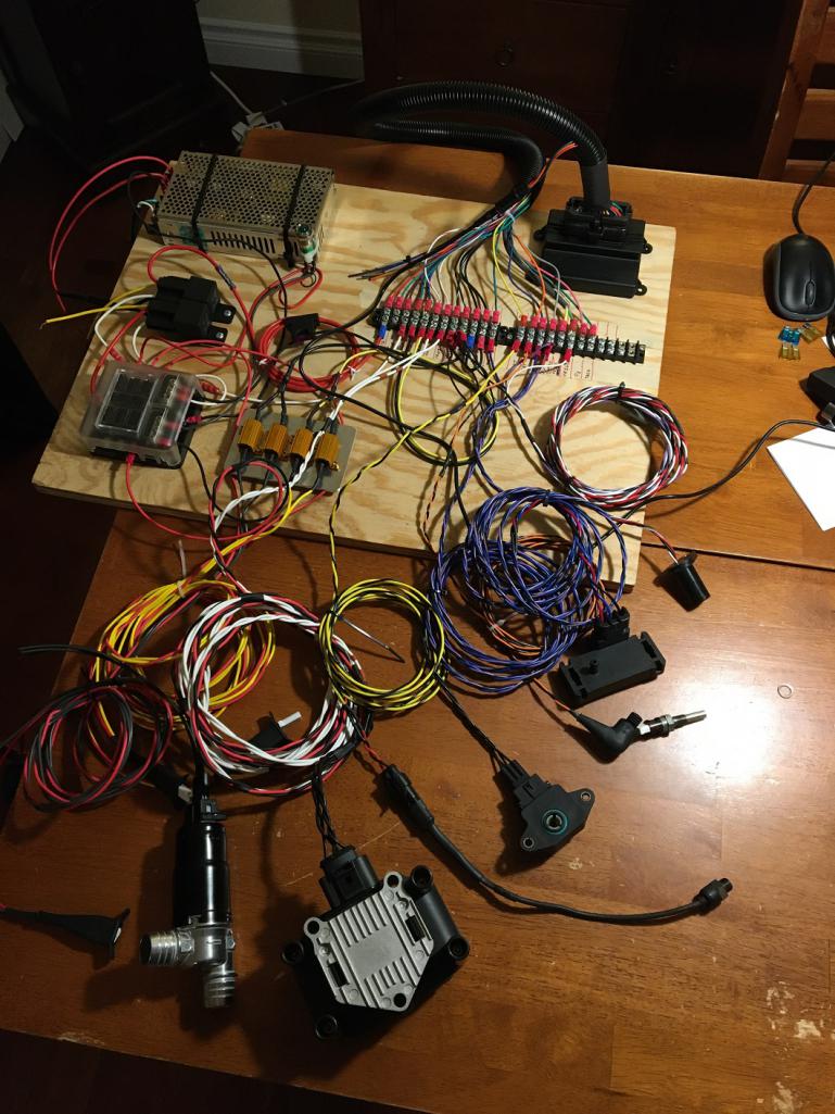 1 Bar GM MAP Sensor: 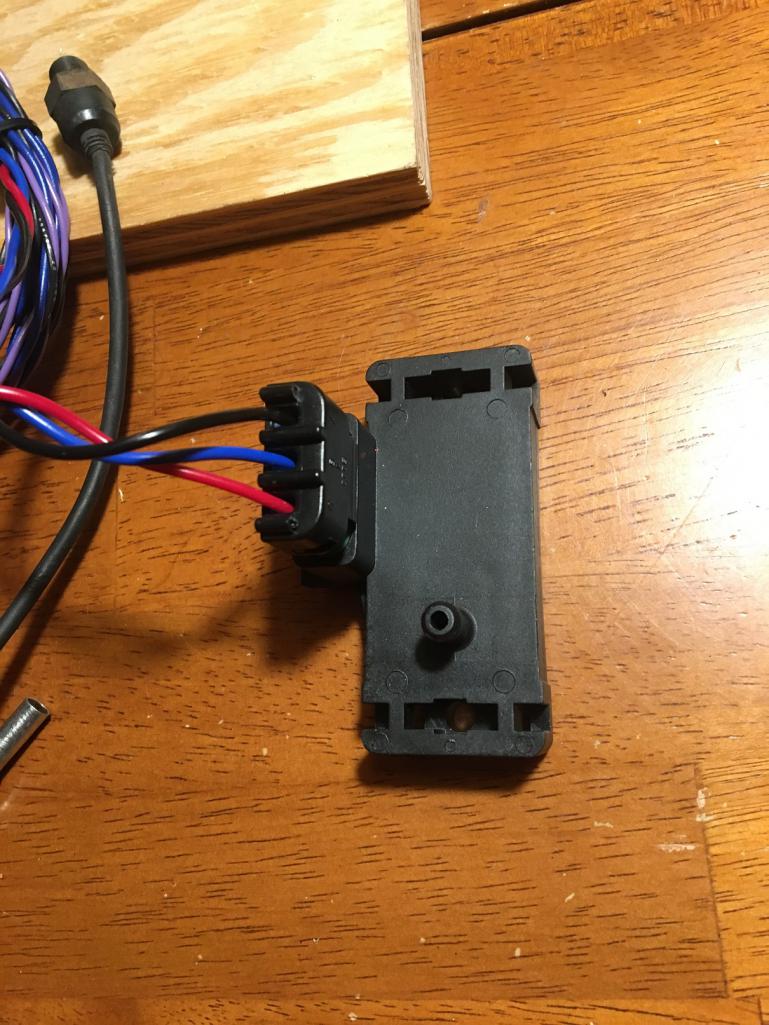 Resistance pack for low impedance green stock injectors. The resistances are not needed if you use modern high impedance injectors. 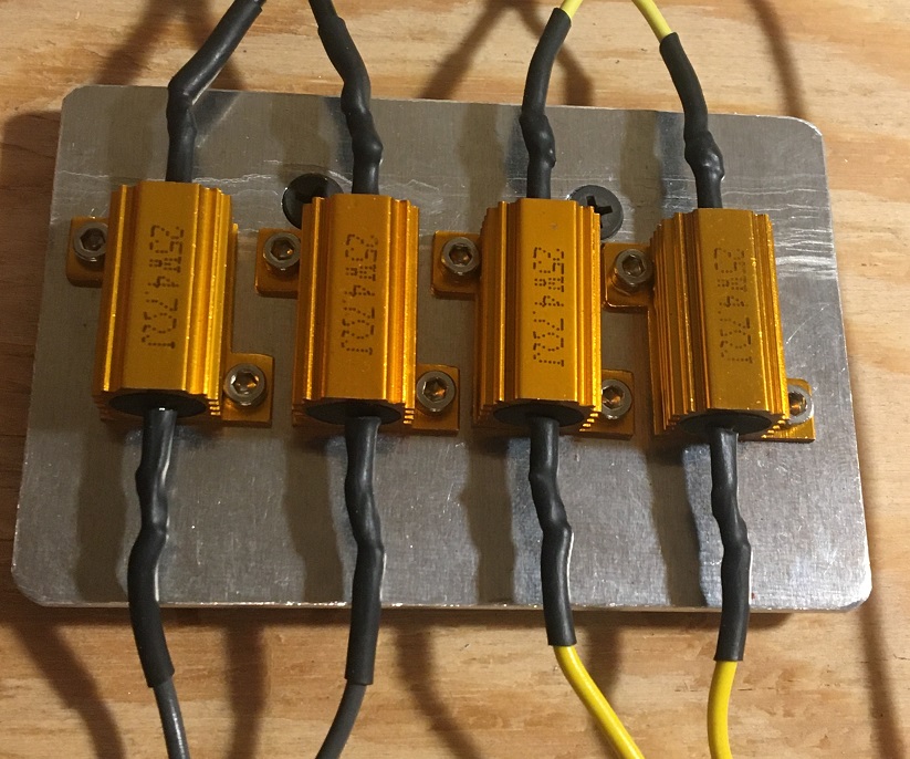 Used BMW Motorcycle Cylinder Head Temp sensor with M10 thread which will screw in the stock 2.0 head CHT location. 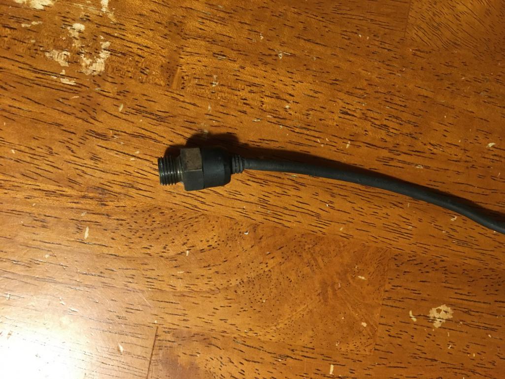 Throttle position switch compatible with the stock 914 throttle body with its 8mm D shape shaft. 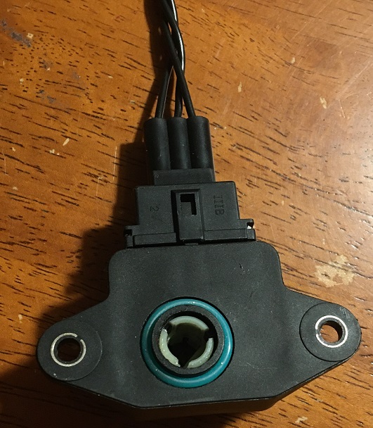 Stock intake air temp sensor with new crimp and connector: 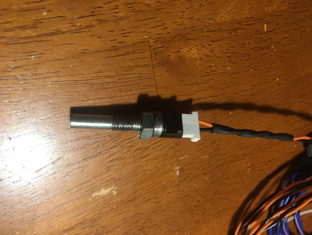 |
  |
Replies
| Montreal914 |
 Feb 29 2020, 11:51 AM Feb 29 2020, 11:51 AM
Post
#2
|
|
Senior Member    Group: Members Posts: 1,699 Joined: 8-August 10 From: Claremont, CA Member No.: 12,023 Region Association: Southern California 
|
A busy (non project related) month has passed already so it's time for me to post some of the updates on the work.
Although I have looked into ways of making the elbow feeding the oil back to the engine one that would have a nice sweep, I didn't come up with any good options. Anyway, I got what I believe to be a forged brass 3/8NPT elbow but the inner passage was not to my liking. The inner sharp corner that results from the machining of the ID from both side was so thin that is was already chipping. Clearly, it had to be massaged (IMG:style_emoticons/default/smash.gif) Before: 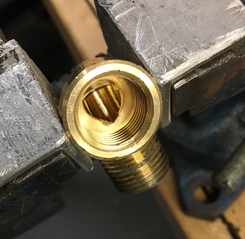 After: This should help to flow around this corner. Not only the passage was increased in size but the inner corner was rounded as much as I could with my various Dremel bits. 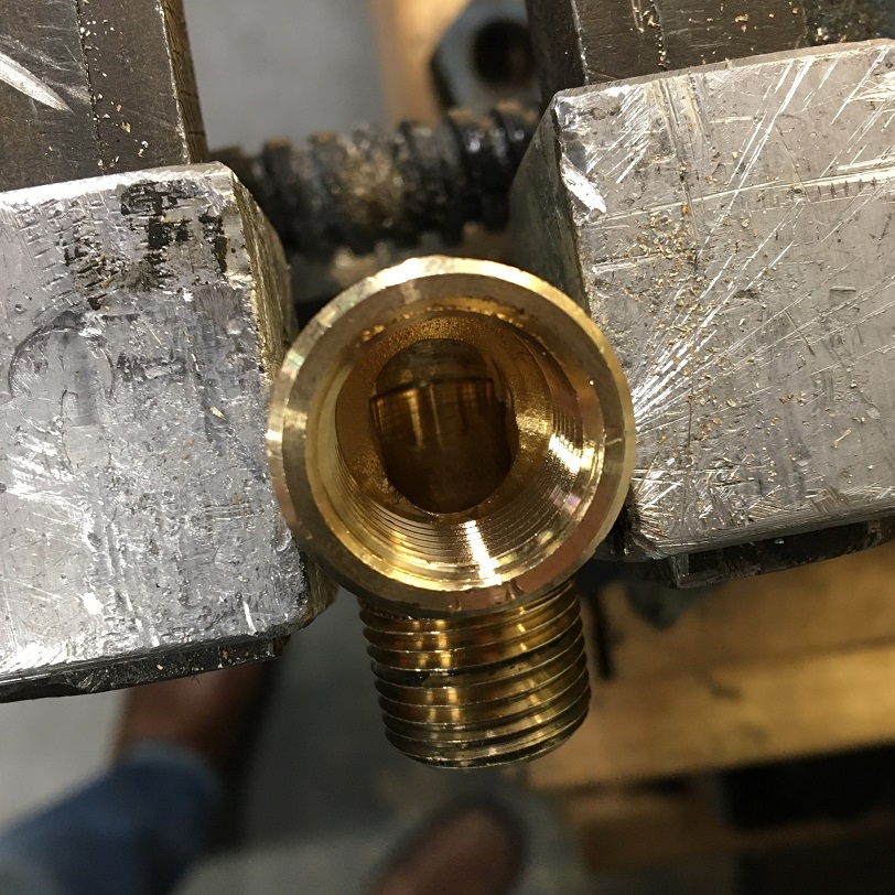 On to installation... The first dry run showed that there might be interference between the elbow and the engine block, so I did a little filing to ensure proper fit. 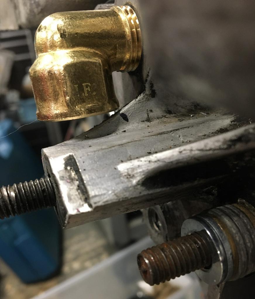 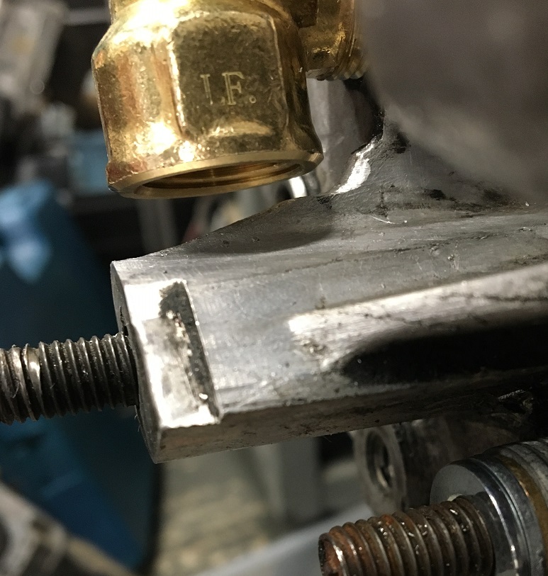 Final clocking: 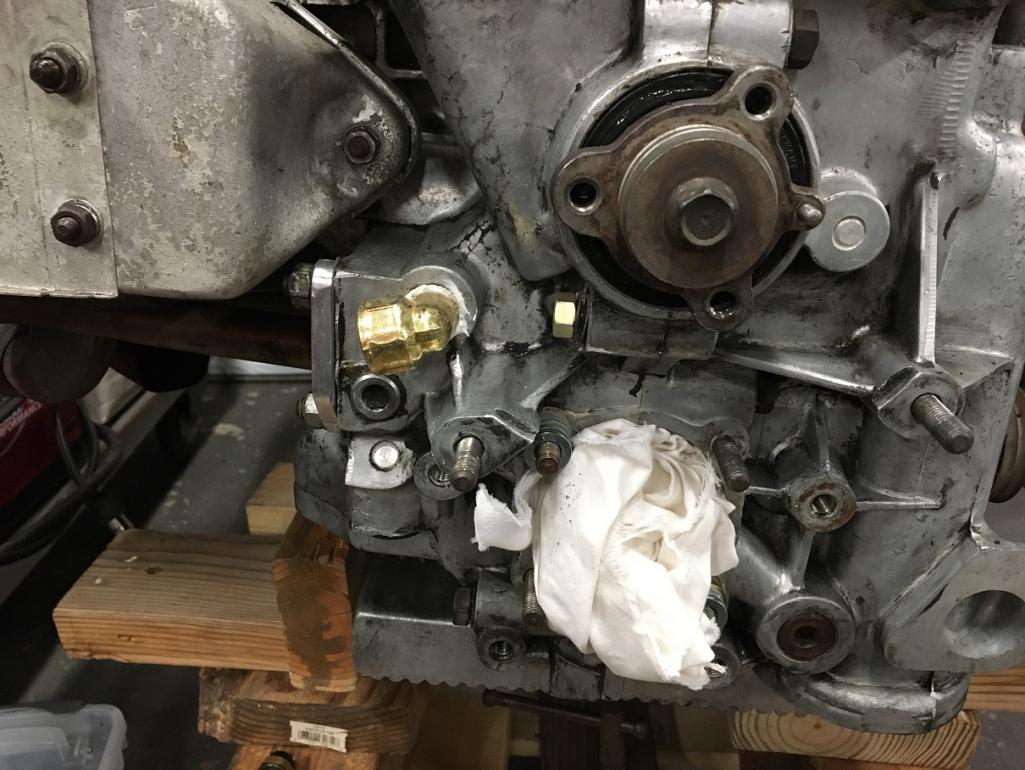 Moving on to the oil pump. My pump is a Type 1 Schadek 30mm, which is considered to be on the larger scale for the type 4 engine. That is why I went with @Mark Henry recommendation to use the Gene Berg pressure relief full flow cover. The issue with using a full flow cover is that the oil line (outlet) interfere's with the passenger side engine mount. There are different options to go around that. In my case, I decided that, for now, I would remove part of one of the two gussets, although this is not ideal. It is also a well know fact that elbows in fluid dynamics are pressure loss points. Ideally, one would use sweep elbow like the -AN tube style. After looking at the various pictures of existing setups documented here, I decided to go with a 45deg 3/8NPT male to 10AN male fitting on the pump cover. Then, my Parker Push-Lok 5/8" ID hose would terminate on a 45 degree sweep elbow 10AN female to mate to the cover fitting. This is helps reduce the pressure loss and minimize the modifications done to the engine mount. Enough talking... on with what people want! Pictures (IMG:style_emoticons/default/smile.gif) Gene Berg pressure relief full flow cover with AN 45deg elbow: 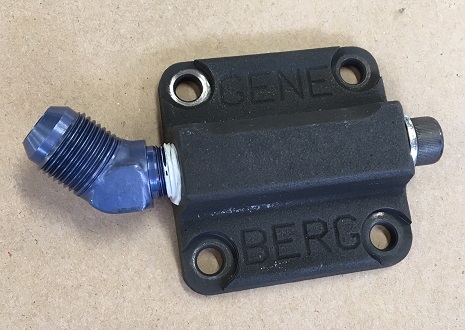 Clocking of the fitting for clearance issues: 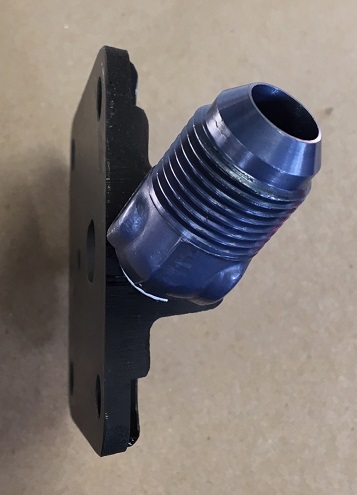 Backside view of the cover where we can see how its design feeds nicely into the outlet port. The other small hole is actually the pressure bypass that feeds back into the pump. Simple. 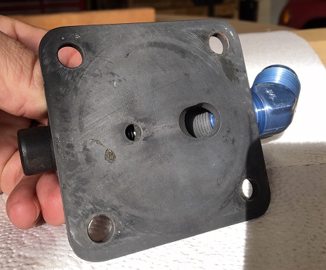 So now that we have this, what is the required clearance needed to the engine mount for all this to work. After a lot of back and forth and removing small portion at a time I came up with this shape to the mount. 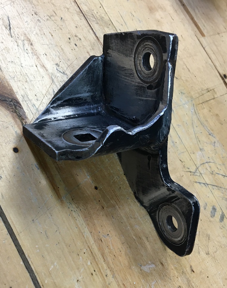 After sanding and rattle can paint: 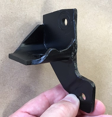 Coming up, engine mount and pump re-installation... |
Posts in this topic
 Montreal914 Microsquirt build, my attempt... And while I am in there... Dec 22 2019, 01:53 PM
 Montreal914 The resistors, as per delivered directly from Chin... Dec 22 2019, 02:04 PM
 jimkelly looking sweet so far. :popcorn: Dec 22 2019, 02:09 PM
 Montreal914 Here I am calibrating the intake air temp sensor. ... Dec 22 2019, 02:28 PM
 Superhawk996 Curious, are you using the Dubshop Individual Thro... Dec 22 2019, 03:26 PM

 Montreal914
Curious, are you using the Dubshop Individual Thr... Dec 22 2019, 03:33 PM

 JamesM
Curious, are you using the Dubshop Individual Th... Dec 23 2019, 05:31 PM
 Montreal914 Moving on to the TPS bracket. As mentioned before,... Dec 22 2019, 03:31 PM

 Superhawk996
I started taking measurement and designing the b... Dec 22 2019, 04:23 PM
 Montreal914 Here is a snapshot of my Excel spreadsheet. I obvi... Dec 22 2019, 03:40 PM

 Mark Henry
Here is a snapshot of my Excel spreadsheet. I obv... Dec 23 2019, 09:47 AM

 JeffBowlsby
And please track/post your time committed to thi... Dec 23 2019, 11:39 AM
 HansJan 95% of what is being said here is beyond my appreh... Dec 22 2019, 05:43 PM
 914werke
Curious why did you go this way vs a new CHT ... Dec 22 2019, 07:22 PM

 Montreal914
Curious why did you go this way vs a new CHT ... Dec 22 2019, 08:24 PM
 KevinW PM sent Dec 22 2019, 08:19 PM
 GregAmy What is the source/application of that TPS? And wi... Dec 23 2019, 06:16 AM
 ChrisFoley Really interested in following this as I have a cu... Dec 23 2019, 11:30 AM
 JamesM Another thing i should add.... Before you get to ... Dec 23 2019, 06:00 PM
 Montreal914 I will try to answer all the questions but before ... Dec 23 2019, 11:12 PM

 JamesM
Based on what you said, I will not use the ICV i... Dec 24 2019, 01:33 AM
 Montreal914 Merry Christmas everyone :wreath:
Personal des... Dec 25 2019, 01:19 PM
 Montreal914 Took a few minutes today to prepare the tool to in... Dec 25 2019, 04:43 PM
 Montreal914 Just came back from a short trip and this was wait... Dec 30 2019, 11:04 PM

 JamesM
I guess I will connect this one to the analog inp... Dec 31 2019, 11:24 AM

 Montreal914
I guess I will connect this one to the analog in... Jan 3 2020, 03:47 PM
 913B Hi, Could you possibly share the amazon link?
Tha... Dec 31 2019, 01:35 AM

 Montreal914
Hi, Could you possibly share the amazon link?
Th... Dec 31 2019, 09:07 AM
 Montreal914 I had a few hours yesterday and today to work on a... Jan 3 2020, 03:55 PM
 Montreal914 Busy weekend! Took the family to JPL's ope... Jan 12 2020, 10:27 PM
 913B BMW mount and rubber elbows tubes? from Where?
So... Jan 13 2020, 12:58 AM

 GregAmy I purchased a Microsquirt as well and will be tryi... Jan 13 2020, 10:37 AM
 Montreal914 Amazon and Ebay are usually my first go to places.... Jan 13 2020, 08:33 AM

 913B
Amazon and Ebay are usually my first go to places... Jan 13 2020, 11:19 PM
 Olympic 914 Liking this, although I also struggle to understan... Jan 13 2020, 09:12 AM

 Montreal914
Liking this, although I also struggle to understa... Jan 13 2020, 10:43 PM
 sixnotfour
:beer2: Thats Awesome :flag1:
Great Microsquirt ... Jan 13 2020, 11:40 AM
 Montreal914 A little more work done this weekend. :smash:
F... Jan 19 2020, 08:27 PM

 JamesM
While I was at it making blanks, I also did one ... Jan 21 2020, 09:44 AM

 Montreal914
While I was at it making blanks, I also did one... Jan 26 2020, 01:17 AM
 Montreal914 Friday I received my 914 Rubber order :mueba: of ... Jan 26 2020, 11:35 AM
 Montreal914 For the oil pump installation, I read here that Pe... Feb 29 2020, 06:29 PM
 Montreal914 I finished preparing the Hall sensor by twisting t... Feb 29 2020, 11:57 PM
 Montreal914 Well it has been a month since my last post, time ... Mar 28 2020, 02:07 PM
 Montreal914 Next step, prepare the oil lines that need to be i... Mar 28 2020, 03:21 PM
 GregAmy :DRUNK:
Eric, maybe I missed it above, but are y... Mar 29 2020, 07:55 AM

 Montreal914
:DRUNK:
Eric, maybe I missed it above, but are ... Mar 29 2020, 12:56 PM
 Montreal914 I did some good progress recently with all of this... Apr 24 2020, 08:25 PM
 GregAmy :beer2: Apr 25 2020, 09:27 AM
 PlaysWithCars Digging the MSD crimping tool and results. I hadn... Apr 25 2020, 11:07 PM
 bohalrantipol Good write up! I am hoping there is an update. Apr 19 2021, 10:37 AM
 Mark Henry Good work! :)
Some peeps question (get mad)... Apr 19 2021, 10:51 AM
 ClayPerrine This is some beautiful work.
If I might make a s... Apr 19 2021, 02:38 PM
 Mark Henry He already has it set up as low impedance, I would... Apr 20 2021, 07:43 AM

 ClayPerrine
He already has it set up as low impedance, I woul... Apr 20 2021, 08:33 AM

 Mark Henry
He already has it set up as low impedance, I wou... Apr 20 2021, 11:46 AM

 GregAmy ...and you don't need custom fuel rails or mou... Apr 20 2021, 12:14 PM

 Mark Henry
...and you don't need custom fuel rails or mo... Apr 20 2021, 12:48 PM

 Mark Henry Dp Apr 20 2021, 12:49 PM

 Mark Henry What are NOS injectors worth? Apr 20 2021, 12:50 PM
 bohalrantipol I am going to post this here as it is pretty thoro... Apr 20 2021, 08:30 AM

 GregAmy If you dont want it here...I will delete it
No wo... Apr 20 2021, 11:44 AM
 Mark Henry Just watch your injector duty cycles, at WOT you w... Apr 20 2021, 11:52 AM
 Montreal914 Thank you for these recent posts!
Yes I am lo... Apr 23 2021, 09:02 PM
  |
12 User(s) are reading this topic (12 Guests and 0 Anonymous Users)
0 Members:

|
Lo-Fi Version | Time is now: 22nd November 2024 - 12:48 PM |
Invision Power Board
v9.1.4 © 2024 IPS, Inc.


