|
|

|
Porsche, and the Porsche crest are registered trademarks of Dr. Ing. h.c. F. Porsche AG.
This site is not affiliated with Porsche in any way. Its only purpose is to provide an online forum for car enthusiasts. All other trademarks are property of their respective owners. |
|
|
| Olympic 914 |
 Feb 10 2017, 07:45 AM Feb 10 2017, 07:45 AM
Post
#1
|
   Group: Members Posts: 1,710 Joined: 7-July 11 From: Pittsburgh PA Member No.: 13,287 Region Association: North East States 
|
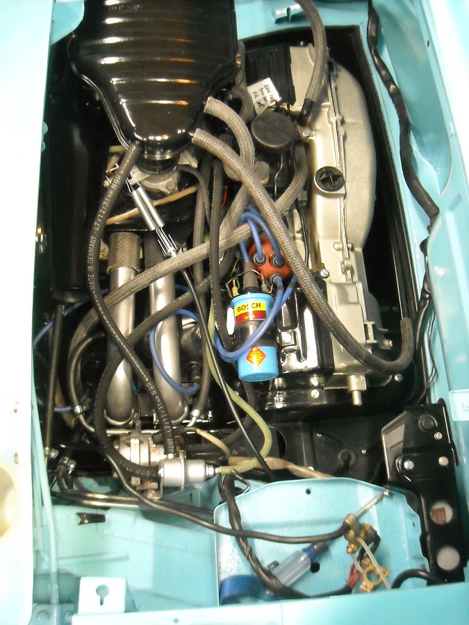
Just finished up installing all the FI wiring harness and the vacuum hoses and now the engine compartment looks like a bowl of Spaghetti.
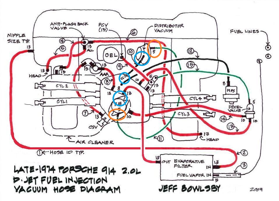
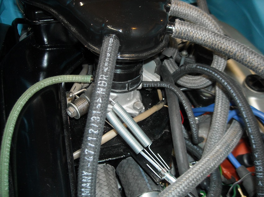
This engine started out as a 73 1.7 with the stock FI and I converted everything to a 2.0 system. I did use some of the original 1.7 parts as they were the same for both engines. But all the 2.0 FI parts ( throttle body, plenum, air filter housing ,etc.) where cobbled together from fleabay purchases and I am not sure what years those parts were from. Also used the original 73 1.7 FI wiring harness and ECU and had to make a couple extensions to get everything to hook up. Not much problem there, (except for trying to connect those ground wires under the plenum. ) Now to the question, I was using Bowlsby's vacuum diagram that is for a late 74 2.0 system and while hooking up the vacuum lines to the dizzy it seem that one line is no longer used.  in the diagram above I have the green vacuum hose connected from the throttle body to the dizzy as shown by the Orange circles. I also have another vacuum port on my dizzy that I have connected to the second vacuum port on my throttle body shown by Blue circles. Should I have both of these hooked up? or do I disconnect the Black vacuum line as shown in Bowlsby's diagram and just plug the second port on the throttle body. This is what I have hooked up now.  Is there a reason that the later versions did not have this second port hooked up? What benefits are there to using the second line to the dizzy vacuum canister? in picture below the green line from the throttle body is routed differently  |
  |
Replies
| mgphoto |
 Feb 10 2017, 09:32 AM Feb 10 2017, 09:32 AM
Post
#2
|
|
"If there is a mistake it will find me"    Group: Members Posts: 1,366 Joined: 1-April 09 From: Los Angeles, CA Member No.: 10,225 Region Association: Southern California |
Good looking job, you will have some issues mixing and matching, dizzys, mps's and ecu's.
The ecu will determine how the vaccum lines are used. One of the hoses is the vacuum retard and the other vacuum advance, that is the reason one of the nipples is above the diaphram and the other below. Off the top of my head, I believe the 1.7 ecu is used with the 2.0l 73 FI, which requires the ballast resistor on the head temp sensor. The 74 2.0l FI deletes the resistor and the vaccum retard, they cap the throttle body and leave the vacuum can unplugged. '74 ecu and dizzy "vacuum can" are tuned. If you don't have the 2.0l dizzy your vaccum signature will not match the vaccum can response. You can either use a 2.0l dizzy or find a vaccum can that has a slotted screw with a locknut in the middle of the can, these can be adjusted to match the vacuum signature. You will also need to turn the mps using an air / fuel ratio meter if you've increased the engine capacity. Unless you have a concorse need, I would remove the deacceleration valve and cap the port on the plenum. Just my 2 cents. Good luck, Mike |
| Olympic 914 |
 Feb 10 2017, 10:37 AM Feb 10 2017, 10:37 AM
Post
#3
|
   Group: Members Posts: 1,710 Joined: 7-July 11 From: Pittsburgh PA Member No.: 13,287 Region Association: North East States 
|
Does your distributor have one or two vacuum ports ? I have two ports on the distributor. The distributor is one of the original 73 1.7 parts. Good looking job, you will have some issues mixing and matching, dizzys, mps's and ecu's. The ecu will determine how the vaccum lines are used. One of the hoses is the vacuum retard and the other vacuum advance, that is the reason one of the nipples is above the diaphram and the other below. Off the top of my head, I believe the 1.7 ecu is used with the 2.0l 73 FI, which requires the ballast resistor on the head temp sensor. The 74 2.0l FI deletes the resistor and the vaccum retard, they cap the throttle body and leave the vacuum can unplugged. '74 ecu and dizzy "vacuum can" are tuned. If you don't have the 2.0l dizzy your vaccum signature will not match the vaccum can response. You can either use a 2.0l dizzy or find a vaccum can that has a slotted screw with a locknut in the middle of the can, these can be adjusted to match the vacuum signature. You will also need to turn the mps using an air / fuel ratio meter if you've increased the engine capacity. Unless you have a concorse need, I would remove the deacceleration valve and cap the port on the plenum. Just my 2 cents. Good luck, Mike I am using the 73 1.7 ECU (#037) and that was also used on the 73 2.0 . I do have a variable POT that I will be using to determine the value needed for the ballast resistor inline from the CHT sensor. Also I have a 043 MPS that was rebuilt and set to the 037 MPS specs that were used on the 73 2.0 I have tried to stay pretty true to the 73 2.0 FI setup, but I have made other changes to the engine, taking it to 2056, using HAM RS+ heads and a Raby 9590 cam. I understand these changes may require a little fine tuning of the MPS and fuel pressure to get it to run correctly. I will be adding a Autometer Wideband AFR gauge to help in the tuning. If both vacuum hoses were connected on the 73 2.0 setup I may just leave them hooked up. unless there is a negative effect to leaving the retard side connected. |
| JamesM |
 Dec 4 2022, 11:57 PM Dec 4 2022, 11:57 PM
Post
#4
|
|
Advanced Member     Group: Members Posts: 2,026 Joined: 6-April 06 From: Kearns, UT Member No.: 5,834 Region Association: Intermountain Region |
I am using the 73 1.7 ECU (#037) and that was also used on the 73 2.0 . I do have a variable POT that I will be using to determine the value needed for the ballast resistor inline from the CHT sensor. Also I have a 043 MPS that was rebuilt and set to the 037 MPS specs that were used on the 73 2.0 I have tried to stay pretty true to the 73 2.0 FI setup, but I have made other changes to the engine, taking it to 2056, using HAM RS+ heads and a Raby 9590 cam. So, its more than just an inline resistor that makes the 1.7 ECU work with the early 73 2.0s, the head temp sensor itself was also unique to that application. You can futz with all the variable resistance you like to get it running good when fully warm but the entire resistance curve is different so warm up mixture is always going to be an issue unless you can find a 0 280 130 017 sensor. These days though it might be easier to just find a 74 or 75 ECU. |
Posts in this topic
 Olympic 1.7 D-Jet vacuum hose question Feb 10 2017, 07:45 AM
 bdstone914 Does your distributor have one or two vacuum ports... Feb 10 2017, 09:00 AM

 Olympic 1.7
Unless you have a concorse need, I would remove ... Feb 10 2017, 10:42 AM
 Jeff Bowlsby That's pretty good advice but a couple of clar... Feb 10 2017, 10:41 AM

 brant
That's pretty good advice but a couple of cla... Feb 10 2017, 04:09 PM

 poorsche914 Have you taken a look at pbanders D-jet page?
Ton... Feb 10 2017, 09:45 PM
 Olympic 1.7 Concerning the Decel valve.
Just to add to the di... Feb 11 2017, 01:31 PM
 mgphoto German's didn't think of everything. If th... Feb 11 2017, 01:35 PM

 Dave_Darling
The de acel valve adds air into the mixture reduc... Feb 12 2017, 09:19 PM

 mgphoto
The de acel valve adds air into the mixture redu... Mar 7 2017, 02:43 PM

 hndyhrr
The de acel valve adds air into the mixture redu... Dec 4 2022, 07:43 PM
 Olympic 1.7 I did rebuild my 043 MPS with one of Tangerines di... Feb 11 2017, 01:48 PM
 Bleyseng You will have to tune the MPS even more to get it ... Feb 12 2017, 11:09 AM
 GregAmy Camping a relevant question onto this discussion t... Mar 7 2017, 08:28 AM

 Olympic 1.7
Camping a relevant question onto this discussion ... Mar 16 2017, 04:19 PM
 Shredhead Also jumping on this thread... I have a late ... Mar 15 2017, 02:27 PM
 The Cabinetmaker Remove and plug both hoses for timing. Mar 15 2017, 04:25 PM
 Mark Henry What is the correct placement for the T in the fue... Jan 15 2021, 04:54 PM
 Olympic 914 this thread was mainly about the vacuum lines.
Bu... Jan 16 2021, 07:26 AM

 GregAmy But in my setup I have the fuel line for the CSV c... Jan 16 2021, 09:52 AM
 Stratfink Getting ready for a throttle body rebuild and plan... Dec 4 2022, 02:14 PM
 wonkipop @Stratfink i suspect this is a bit similar to the... Dec 4 2022, 03:24 PM
 914sgofast2 I have a 1970 1.7liter without the deceleration v... Dec 4 2022, 08:03 PM
 JeffBowlsby Decel valve was added in 1972. Could be retrofitt... Dec 4 2022, 10:29 PM
 wonkipop pay attention
@hndyhrr
[b]@[url=http://www.914... Dec 5 2022, 02:18 AM
 JeffBowlsby I had answered this previously in this same thread... Dec 5 2022, 10:15 AM
 wonkipop
I had answered this previously in this same threa... Dec 5 2022, 05:42 PM
 JeffBowlsby In the wild and crazy portion of my mis-spent yout... Dec 5 2022, 07:08 PM
 wonkipop
In the wild and crazy portion of my mis-spent you... Dec 6 2022, 06:12 PM
  |
22 User(s) are reading this topic (22 Guests and 0 Anonymous Users)
0 Members:

|
Lo-Fi Version | Time is now: 9th January 2025 - 06:40 AM |
Invision Power Board
v9.1.4 © 2025 IPS, Inc.


