|
|
|
Porsche, and the Porsche crest are registered trademarks of Dr. Ing. h.c. F. Porsche AG.
This site is not affiliated with Porsche in any way. Its only purpose is to provide an online forum for car enthusiasts. All other trademarks are property of their respective owners. |
|
|


| jk76.914 |
 Jul 15 2007, 06:24 PM Jul 15 2007, 06:24 PM
Post
#1
|
|
Senior Member  Group: Members Posts: 809 Joined: 12-April 05 From: Massachusetts Member No.: 3,925 Region Association: North East States |
Well, I have this hydraulic cam in my engine. And last fall I committed to making it work, and so now I have an update.
I'm hoping I won't get called a moron again! But here I go! This will probably be done in 3 parts- lifters, pushrods, and rockers. So I got convinced that the real issue with hydros is lack of adequate lube to the rocker boxes. I found a website that was discussing major problems with Lycoming (4 cylinder, air-cooled aircraft engines) when they transitioned to hydraulics in the late 70's. That was about the same time VW and Continental (aircraft) transitioned. VW had very similar problems, but Continental was virtually trouble-free. Many (all?) of the Lycoming problems can be explained by their implementation of hydros as opposed to the well known fact in 914 circles that hydos are, in fact, evil. In the article, it is observed that the hydraulic lifter has two roles- 1.) to adjust to changes in engine tolerances due to wear and temperature and keep the valves at zero lash, and 2.) to convey oil up the pushrods so as to lube the rockers. Inadequate oiling means inadequate cooling, stuck valves (due to oil coking on the stems), broken valves, bent pushrods, galled lifters and cams, etc, etc, etc... sound familiar? sound evil? How about valves failing (shattering) in flight? In the article, the authors go on to "point out a major shortcoming of the Lycoming design that we believe substantially accounts for valve train problems including stuck exhaust valves, prematurely worn valves and guides, and camshaft distress and failure." The early implementation in Lycoming (and VW?) focused on the first role and missed the second. I'm open to correction, but I think this was the VERY first use of hydraulic valve actuators by VW. Anyway, here's the article: http://www.prime-mover.org/Engines/Marvel/tbo3.html Every time I read it I get something more out of it.... It also touches on sodium filled valves... On my own engine, I noticed that when I adjusted the hydros to +.006" (clearance) and then idled it, there was significant oil flowing out and all over my driveway. (This in spite of the fact that I installed a half valve cover to catch oil.) When I then adjusted to -.006", the flow virtually stopped- the pushrod seated in the rocker like a valve in its seat. I re-read the article, and then started at the lifter. I bought three brands of T4 lifter- Meyle, Febi, and Isky. I disassembled them and looked at the various schemes of metering oil to the head. 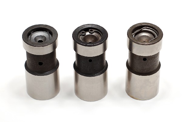 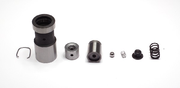 Meyle Meyle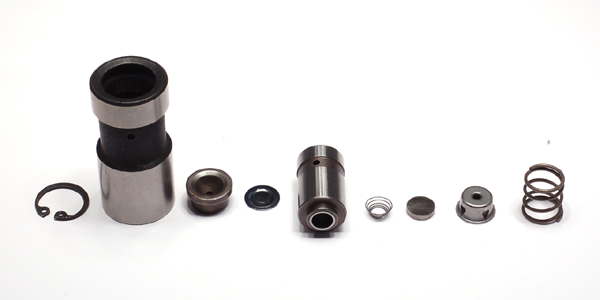 Febi (may be the same as Sealed Power) Febi (may be the same as Sealed Power)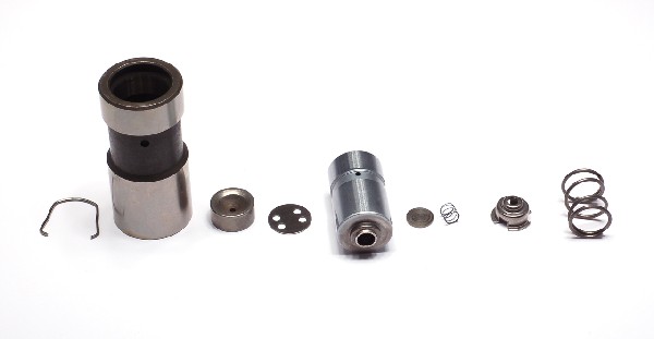 Isky (may be made by Delphi?) Isky (may be made by Delphi?)Both the Febi and the Isky have a metering disk beneath the pushrod seat that meters oil from the plunger to the pushrod. The Meyle relies on oil leakage around the pushrod seat and then into the side hole and then through the pushrod seat to the pushrod. This does not seem to me to be a reliable way to forward oil up the pushrod. Also, there is a reference to two designs of VW hydraulic lifter at this article- http://www.ratwell.com/technical/HydraulicLifters.html . In the article, Richard Atwell speculates that VW improved the design because it changed from having a paper clip style retainer to having a circlip retainer to hold it all together. Well, Meyle (questionable oiling) has a paper clip style retainer, and Febi (improved oiling) has the circlip. My theory is that VW migrated from Meyle to Febi, because the Meyle was causing failures due to inadequate lube. It's all anecdotal and speculative, but for the life of me I can't imagine how the Meyle can reliably and predictably convey oil to the head..... (beating the same dead horse) 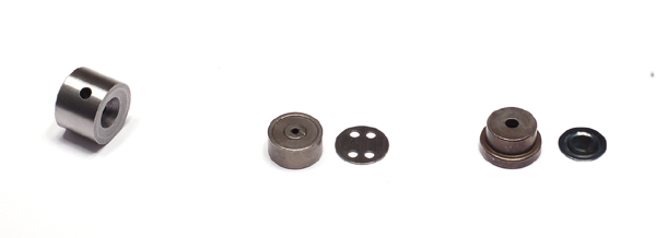 Meyle, Isky, Febi oil metering to pushrod. Meyle, Isky, Febi oil metering to pushrod.In addition to the article on Lycoming and Continental, I looked closely at Corvair (freakin' Chevy to some). 1.7 million Corvairs were built over a 10 year period, and all had hydraulic lifters. And they were never considered a reliability issue. The Corvair is basically a six cylinder Type 4 (though Corvair predates T4 by almost 10 years). So I also purchased 2 Corvair lifters- one used original Chevy and one new Sealed Power. Upon disassembly, I found oiling similar to the Isky and the Febi- both have a method of metering the oil, as opposed to relying on leakage. When GM discontinued the original Corvair part number, there was quite a bit of activity on the internet about substitutes and how effective they are in transferring oil to the rockers, so clearly it's a more openly understood requirement with the Corvair-meisters than with us T4 guys whose starting point is solid lifters...... (one of these days I'll get around to taking photos of the Corvair lifters) So anyway, after I was satisfied with which lifter I would use (I stuck with my Iskys, thought I wouldn't hesitate to use Febi either), I moved on to the pushrods.... and I'll get into that in my next post, probably in a few days.... |
   |

 
|
  |
Replies
| jk76.914 |
Jul 16 2007, 08:39 PM
Post
#2
|
|
Senior Member Group: Members Posts: 809 Joined: 12-April 05 From: Massachusetts Member No.: 3,925 Region Association: North East States |
Thanks for all the replies. I wanted to get into the pushrods next. Sorry I launched earlier by mistake- here's the whole story-
So for the pushrods, I needed to address two issues- my kit pushrods were obviously too short, but I also needed to continue my quest for lubrication to the head. So I looked again to the Corvair. The Corvair pushrod has two holes on one end- one on the tip and an additional .020" hole on the side. Since the pushrod rotates with the lifter, and goes up and down, that side hole sprays oil around like a lawn sprinkler. In the Corvair case, there are 6 of those sprinkler heads in each rocker box, and believe me, it moves a lot of oil to the rocker box. 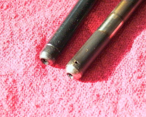 Kit pushrod and used Corvair pushrod. Kit pushrod and used Corvair pushrod.Unfortunately, the Corvair pushrod seemed too long, and besides, the hole was too near the end- it was shrouded by the cup in the rocker that the pushrod seated into. So I looked for alternatives, including laser drilling a side hole in the hardened tip of a new pushrod, but I struck out. Then I started thinking about length. With hydraulic lifters, when you adjust the screw, you are effectively changing the pushrod length. Think about it. If you screw the adjuster in, the valve doesn't open. No, the lifter plunger goes further into the lifter body and self-adjusts to that new position. In a solid lifter engine you get the same effect by shortening the pushrod. So how do I determine the "correct" pushrod length? While I thought about that, I looked at the wear pattern on the tip of the adjuster screw. The tip has a spherically ground surface. With my short pushrods, this "skid mark" was skewed towards the edge nearest the rocker shaft, and the mark was very long. So the screw was sliding across the valve tip as it opened the valve, and then retreating as it closed the valve. Thinking about the geometry, I realized that the slide of the adjuster screw across the valve tip is minimized when the axis of the screw is perpendicular to a radius from the center of the rocker shaft, which is the pivot point.... A picture is worth a thousand words- 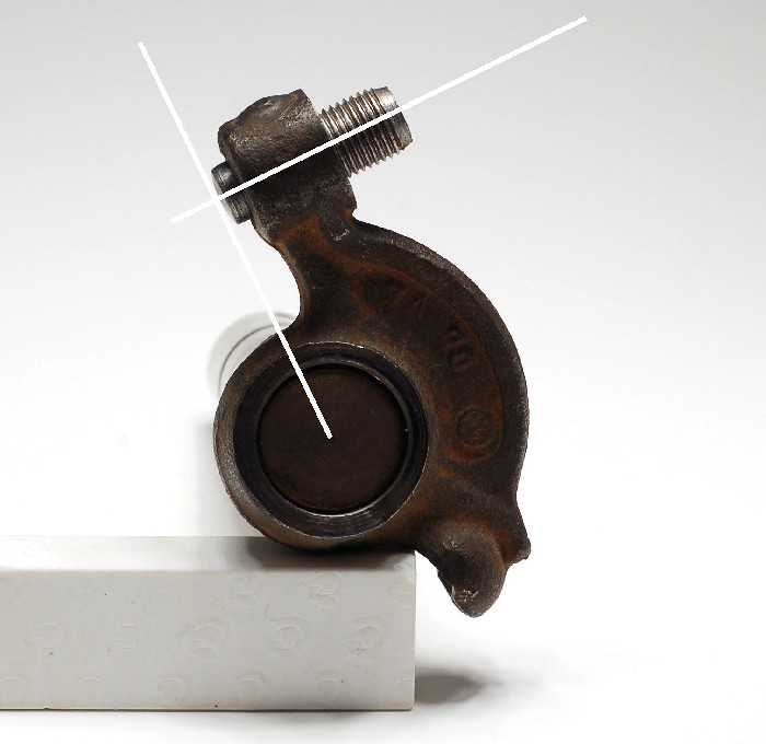 If you move the screw either in or out from this position, you move the tip further from the pivot centerline, and so its motion resulting from a fixed angular swing of the rocker increases. To determine pushrod length, I started by setting the adjuster screw to this nominal position. I also made a tool- I took two Meyle lifters and assembled them with carefully cut lengths of pushrod tubing in the bottom, also filling the cavity with Gorilla glue. The tubing was cut to provide a pushrod seat height that is -.030" below the free length of a standard lifter. This gave me a "solid lifter" that emulated a 1 turn lash from zero- .030" x 1.3 (rocker ratio) = .040", which is extremely close to 1mm at the valve, which is 1 turn (10mm x 1 thread pitch). 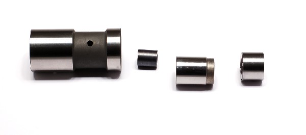 Now I could put the modified lifters into the lifter bore, assemble with a test pushrod, turn the engine over 2 turns, and observe the valve geometry. Keep trying different length pushrods until it looked right at half lift, and I'm done. The only trouble was, I was doing this with the engine in the car, and even though I managed to rig my dial indicator to find half lift, visualizing the screw axis being perpendicular to the valve stem was tough. I tried photographing it and then enlarging the photos, which actually worked, but it wasn't easy or precise- too visual. So I tried taking advantage of the skid mark on the adjuster screw. I know that when my pushrods were too short, the mark was skewed off the edge, and that on my original screws on my original solid cam, they were nicely centered and short. So I tried coating the adjuster tip with blue dykem, carefully assembling the shaft, installing the assembled shaft onto the engine, and then turning the engine over my 2 turns. The movement of the screw across the valve stem tip left a very nice mark on the screw that I could "read" standing up in the comfort of my workshop. 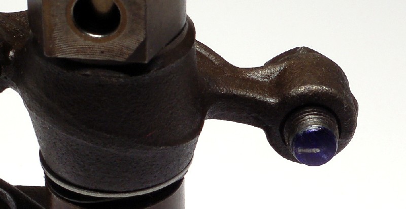 This pushrod is too short. I could have improved this by turning the screw out, but I wanted to try and get close to perfect at 1 turn. That gives me +/- 1/2 turn to tweak to perfection. So I tried a longer pushrod- 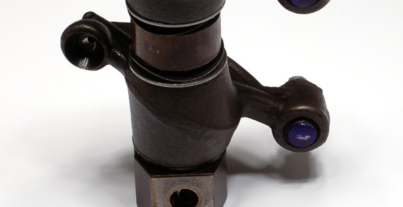 (I know this isn't the same one, but it illustrates the process. Also, this one is at the "nominal" screw position- see how short it is?) I THINK THIS WOULD BE A GREAT WAY TO CHECK VALVE GEOMETRY ON A SOLID LIFTER ENGINE! (assuming you're using 10mm stock adjusters anyway) Just lash to spec, snug up the lock nuts, remove the rockers and shaft intact, clean, blue dykem, reinstall, turn over 2 turns, remove, and look at what you have. Interestingly, to hold the adjuster screw to my "nominal" position, I had to shorten 6 of my rocker pedistals by .020". (Later I actually did the math, and learned that the amount of slide is very INSENSITIVE to the screw being off nominal. Oh well.) MORE AMAZING- when I got through it all, turns out that the CORVAIR STANDARD LENGTH PUSHROD WAS PRECISELY THE CORRECT LENGTH ON MY 914!!!! It wasn't too long after all! I have nicely centered and short skid marks on my adjuster screws. Way different from the kit rods, which were about .200" too short- 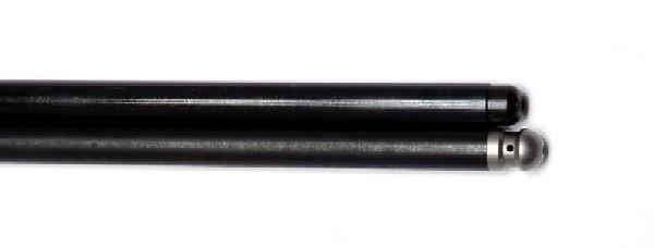 Isky kit vs. Otto Parts Corvair. Isky kit vs. Otto Parts Corvair.The Otto Parts pushrod is now sold by Clark's Corvair Parts. This one is standard Corvair 10 7/32", but they are available in about .025" increments in about 10 lengths. Actual length required is greatly a function of your cam- base circle diameter as well as lift. With my Isky 229-hyd it happens to be the stock Corvair length. The last piece of the puzzle was the oil hole. I decided to use the Corvair parts, and I solved the shrouding issue by grinding a relief in the rocker, being sure not to go near the polished part the pushrod seats into. The other big advantage of this approach- if I had found a way to redrill lower on the pushrod to clear the rocker cap, I would have buried it into the pushrod tube- even worse.  The pushrod isn't seated in the rocker in the photo, but you can see how I ground back the rocker to unshroud the oil hole. I got better as I went along! But notice that I only ground the half of the cap nearest the rocker shaft? I didn't want the oil to spray directly onto the valve cover gasket as the pushrod turns. Also, there isn't a straight shot with the VW valve scheme anyway, so I'm relying on filling the rocker boxes with an oil mist as much as spraying directly on any particular point. So that's where I ended up with pushrods. There's a eplilog to the pushrod discussion though, but it'll wait for the rocker installment. |
|
|
|
Posts in this topic
 jk76.914 New views on hydraulic cams. Jul 15 2007, 06:24 PM
 Dave_Darling Interesting... IIRC, lack of rocker (and associat... Jul 15 2007, 07:59 PM McMark Thanks! Looking forward to the rest of the ... Jul 15 2007, 08:08 PM 914Sixer Very interesting article. I just pulled apart a 1... Jul 15 2007, 08:56 PM
 jk76.914
Very interesting article. I just pulled apart a ... Jul 16 2007, 05:09 AM sww914 Very interesting post. Thanks for doing all the re... Jul 15 2007, 09:43 PM Jake Raby A large portuion of the problem with Hydro equippe... Jul 16 2007, 06:02 AM Johny Blackstain :popcorn: !
I am no mechanical engineer but ... Jul 16 2007, 06:26 AM jk76.914
:popcorn: !
I am no mechanical engineer but... Jul 17 2007, 01:04 PM jk76.914
:popcorn: !
I am no mechanical engineer but... Jul 18 2007, 09:12 PM Johny Blackstain
Forget to reply to the Mercedes injectors- they... Jul 18 2007, 09:16 PM Jake Raby Yes, I have purposely neglected my engines for the... Jul 16 2007, 06:44 AM rjames jk76.914, your timing is perfect.
I have hydros i... Jul 16 2007, 03:21 PM Jake Raby Loud hydros are usually due to oil pressure issues... Jul 16 2007, 03:33 PM jk76.914 Thanks for all the replies. I wanted to get into ... Jul 16 2007, 07:14 PM Bleyseng Hell, I have always thought with the head half ful... Jul 16 2007, 07:37 PM jk76.914
Hell, I have always thought with the head half fu... Jul 16 2007, 08:43 PM Jake Raby When all your oil ends up in the valve covers and ... Jul 16 2007, 07:44 PM jk76.914
When all your oil ends up in the valve covers and... Jul 16 2007, 08:43 PM Jake Raby One thing to consider is the fact that adding thos... Jul 16 2007, 08:43 PM jk76.914
One thing to consider is the fact that adding tho... Jul 16 2007, 08:55 PM Jake Raby Solid lifters do not rely on oil pressure to funct... Jul 16 2007, 09:01 PM rjames What weight of oil and type (synthetic or non) is ... Jul 17 2007, 02:04 AM jk76.914
What weight of oil and type (synthetic or non) is... Jul 17 2007, 05:33 AM Jake Raby You need to change that oil every 3 months, even i... Jul 17 2007, 08:43 AM SGB I use 20W50 Castrol changed every few months with ... Jul 17 2007, 08:18 PM morph I have started to experiment with motors,and to ha... Jul 17 2007, 11:26 PM 914-8 I did some similar research regarding hydraulic li... Jul 18 2007, 10:15 PM jk76.914
I did some similar research regarding hydraulic l... Jul 19 2007, 04:58 PM Jake Raby My opinion is that having hydraulic adjustment imp... Jul 18 2007, 10:18 PM jk76.914 I'll try and finish up my brain dump tonight. ... Jul 19 2007, 05:00 PM jk76.914 OK, last installment. I know the lifter selection... Jul 20 2007, 08:56 PM MecGen Hey
Man....serious good work here ! :popcorn... Jul 21 2007, 06:02 AM jk76.914
Hey
Man....serious good work here ! :popcor... Jul 21 2007, 08:43 AM Dr Evil Very cool and concise write up, thanks! :thumb... Jul 21 2007, 11:20 AM Coy
I have a 2 liter with hydraulic lifters & tw... Jul 21 2007, 05:58 PM MecGen Hah
I knew you were a hightec type of guy :DRUNK... Jul 22 2007, 07:03 AM jk76.914
Hah
I knew you were a hightec type of guy :DRUN... Jul 22 2007, 10:05 AM
jk76.914
Very interesting article. I just pulled apart a ... Jul 16 2007, 05:09 AM sww914 Very interesting post. Thanks for doing all the re... Jul 15 2007, 09:43 PM Jake Raby A large portuion of the problem with Hydro equippe... Jul 16 2007, 06:02 AM Johny Blackstain :popcorn: !
I am no mechanical engineer but ... Jul 16 2007, 06:26 AM jk76.914
:popcorn: !
I am no mechanical engineer but... Jul 17 2007, 01:04 PM jk76.914
:popcorn: !
I am no mechanical engineer but... Jul 18 2007, 09:12 PM Johny Blackstain
Forget to reply to the Mercedes injectors- they... Jul 18 2007, 09:16 PM Jake Raby Yes, I have purposely neglected my engines for the... Jul 16 2007, 06:44 AM rjames jk76.914, your timing is perfect.
I have hydros i... Jul 16 2007, 03:21 PM Jake Raby Loud hydros are usually due to oil pressure issues... Jul 16 2007, 03:33 PM jk76.914 Thanks for all the replies. I wanted to get into ... Jul 16 2007, 07:14 PM Bleyseng Hell, I have always thought with the head half ful... Jul 16 2007, 07:37 PM jk76.914
Hell, I have always thought with the head half fu... Jul 16 2007, 08:43 PM Jake Raby When all your oil ends up in the valve covers and ... Jul 16 2007, 07:44 PM jk76.914
When all your oil ends up in the valve covers and... Jul 16 2007, 08:43 PM Jake Raby One thing to consider is the fact that adding thos... Jul 16 2007, 08:43 PM jk76.914
One thing to consider is the fact that adding tho... Jul 16 2007, 08:55 PM Jake Raby Solid lifters do not rely on oil pressure to funct... Jul 16 2007, 09:01 PM rjames What weight of oil and type (synthetic or non) is ... Jul 17 2007, 02:04 AM jk76.914
What weight of oil and type (synthetic or non) is... Jul 17 2007, 05:33 AM Jake Raby You need to change that oil every 3 months, even i... Jul 17 2007, 08:43 AM SGB I use 20W50 Castrol changed every few months with ... Jul 17 2007, 08:18 PM morph I have started to experiment with motors,and to ha... Jul 17 2007, 11:26 PM 914-8 I did some similar research regarding hydraulic li... Jul 18 2007, 10:15 PM jk76.914
I did some similar research regarding hydraulic l... Jul 19 2007, 04:58 PM Jake Raby My opinion is that having hydraulic adjustment imp... Jul 18 2007, 10:18 PM jk76.914 I'll try and finish up my brain dump tonight. ... Jul 19 2007, 05:00 PM jk76.914 OK, last installment. I know the lifter selection... Jul 20 2007, 08:56 PM MecGen Hey
Man....serious good work here ! :popcorn... Jul 21 2007, 06:02 AM jk76.914
Hey
Man....serious good work here ! :popcor... Jul 21 2007, 08:43 AM Dr Evil Very cool and concise write up, thanks! :thumb... Jul 21 2007, 11:20 AM Coy
I have a 2 liter with hydraulic lifters & tw... Jul 21 2007, 05:58 PM MecGen Hah
I knew you were a hightec type of guy :DRUNK... Jul 22 2007, 07:03 AM jk76.914
Hah
I knew you were a hightec type of guy :DRUN... Jul 22 2007, 10:05 AM |
1 User(s) are reading this topic (1 Guests and 0 Anonymous Users)
0 Members:

|
Lo-Fi Version | Time is now: 14th March 2026 - 11:12 AM |
Invision Power Board
v9.1.4 © 2026 IPS, Inc.