|
|
|
Porsche, and the Porsche crest are registered trademarks of Dr. Ing. h.c. F. Porsche AG.
This site is not affiliated with Porsche in any way. Its only purpose is to provide an online forum for car enthusiasts. All other trademarks are property of their respective owners. |
|
|


| jk76.914 |
 Jul 15 2007, 06:24 PM Jul 15 2007, 06:24 PM
Post
#1
|
|
Senior Member  Group: Members Posts: 809 Joined: 12-April 05 From: Massachusetts Member No.: 3,925 Region Association: North East States |
Well, I have this hydraulic cam in my engine. And last fall I committed to making it work, and so now I have an update.
I'm hoping I won't get called a moron again! But here I go! This will probably be done in 3 parts- lifters, pushrods, and rockers. So I got convinced that the real issue with hydros is lack of adequate lube to the rocker boxes. I found a website that was discussing major problems with Lycoming (4 cylinder, air-cooled aircraft engines) when they transitioned to hydraulics in the late 70's. That was about the same time VW and Continental (aircraft) transitioned. VW had very similar problems, but Continental was virtually trouble-free. Many (all?) of the Lycoming problems can be explained by their implementation of hydros as opposed to the well known fact in 914 circles that hydos are, in fact, evil. In the article, it is observed that the hydraulic lifter has two roles- 1.) to adjust to changes in engine tolerances due to wear and temperature and keep the valves at zero lash, and 2.) to convey oil up the pushrods so as to lube the rockers. Inadequate oiling means inadequate cooling, stuck valves (due to oil coking on the stems), broken valves, bent pushrods, galled lifters and cams, etc, etc, etc... sound familiar? sound evil? How about valves failing (shattering) in flight? In the article, the authors go on to "point out a major shortcoming of the Lycoming design that we believe substantially accounts for valve train problems including stuck exhaust valves, prematurely worn valves and guides, and camshaft distress and failure." The early implementation in Lycoming (and VW?) focused on the first role and missed the second. I'm open to correction, but I think this was the VERY first use of hydraulic valve actuators by VW. Anyway, here's the article: http://www.prime-mover.org/Engines/Marvel/tbo3.html Every time I read it I get something more out of it.... It also touches on sodium filled valves... On my own engine, I noticed that when I adjusted the hydros to +.006" (clearance) and then idled it, there was significant oil flowing out and all over my driveway. (This in spite of the fact that I installed a half valve cover to catch oil.) When I then adjusted to -.006", the flow virtually stopped- the pushrod seated in the rocker like a valve in its seat. I re-read the article, and then started at the lifter. I bought three brands of T4 lifter- Meyle, Febi, and Isky. I disassembled them and looked at the various schemes of metering oil to the head. 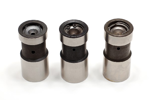 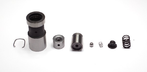 Meyle Meyle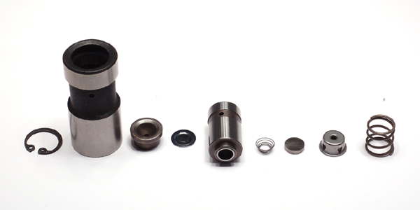 Febi (may be the same as Sealed Power) Febi (may be the same as Sealed Power)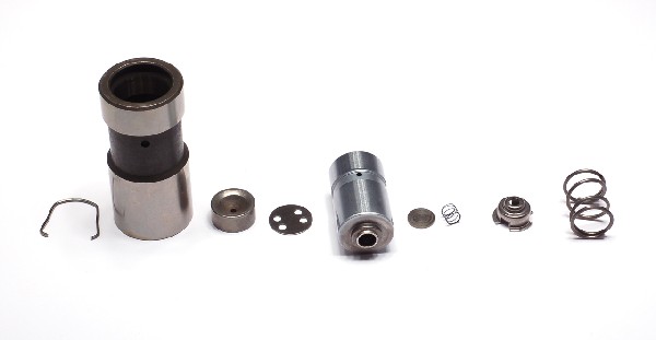 Isky (may be made by Delphi?) Isky (may be made by Delphi?)Both the Febi and the Isky have a metering disk beneath the pushrod seat that meters oil from the plunger to the pushrod. The Meyle relies on oil leakage around the pushrod seat and then into the side hole and then through the pushrod seat to the pushrod. This does not seem to me to be a reliable way to forward oil up the pushrod. Also, there is a reference to two designs of VW hydraulic lifter at this article- http://www.ratwell.com/technical/HydraulicLifters.html . In the article, Richard Atwell speculates that VW improved the design because it changed from having a paper clip style retainer to having a circlip retainer to hold it all together. Well, Meyle (questionable oiling) has a paper clip style retainer, and Febi (improved oiling) has the circlip. My theory is that VW migrated from Meyle to Febi, because the Meyle was causing failures due to inadequate lube. It's all anecdotal and speculative, but for the life of me I can't imagine how the Meyle can reliably and predictably convey oil to the head..... (beating the same dead horse) 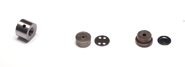 Meyle, Isky, Febi oil metering to pushrod. Meyle, Isky, Febi oil metering to pushrod.In addition to the article on Lycoming and Continental, I looked closely at Corvair (freakin' Chevy to some). 1.7 million Corvairs were built over a 10 year period, and all had hydraulic lifters. And they were never considered a reliability issue. The Corvair is basically a six cylinder Type 4 (though Corvair predates T4 by almost 10 years). So I also purchased 2 Corvair lifters- one used original Chevy and one new Sealed Power. Upon disassembly, I found oiling similar to the Isky and the Febi- both have a method of metering the oil, as opposed to relying on leakage. When GM discontinued the original Corvair part number, there was quite a bit of activity on the internet about substitutes and how effective they are in transferring oil to the rockers, so clearly it's a more openly understood requirement with the Corvair-meisters than with us T4 guys whose starting point is solid lifters...... (one of these days I'll get around to taking photos of the Corvair lifters) So anyway, after I was satisfied with which lifter I would use (I stuck with my Iskys, thought I wouldn't hesitate to use Febi either), I moved on to the pushrods.... and I'll get into that in my next post, probably in a few days.... |
   |

 
|
  |
Replies
| jk76.914 |
Jul 20 2007, 08:56 PM
Post
#2
|
|
Senior Member Group: Members Posts: 809 Joined: 12-April 05 From: Massachusetts Member No.: 3,925 Region Association: North East States |
OK, last installment. I know the lifter selection is very important to rocker oiling, and I've added a squirt hole (a la Corvair) at the top of the pushrods to make up for oil that isn't getting there through the valve clearance. I see no downside to either.
Now, how to get the oil to where it's needed- the valve stem tips and the guides? In SAE Paper 140C (Chevrolet Corvair engine) it is stated that the oiler holes were put in the pushrods because the pushrods enter the rocker box below the rockers and valves, and this was their means of getting the oil to go up north where it's needed. Some of this engineering team had transitioned from the original small block Chevy project, and were pretty familiar with its oiling, where the pushrods that enter from above give the oil a gravity assist. 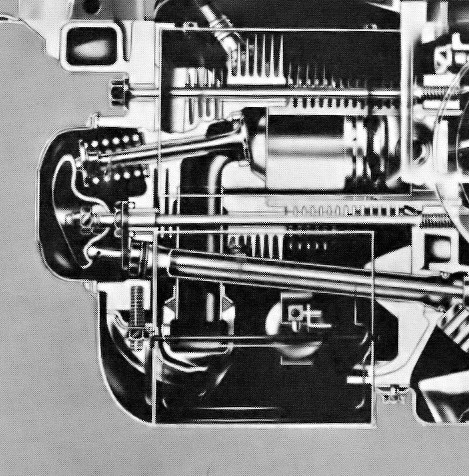 Since Corvair rocker arms are Chevy ball and stud affairs, just like on the venerable SBC, there was lots of space between the rockers for the oil to spray, unlike the T4 which has that big old rocker shaft. So this was my problem. These engines are engineered as systems, and you can't always swap one part from one system (pushrods, in this case) with the same part in another and expect it to do the same job it did in the original system (or engine). The Corvair pushrods definitely pump more oil to the heads than standard T4 pushrods (particularly at zero lash), but is it enough oil, and does enough get to where it's needed? I frankly don't know. So that's what I was thinking when I looked at the T4 rockers. These rockers have oil passages going from the pushrod up to the shaft bore. The shaft has a relief that acts as a channel for the oil to flow around it and get picked up by another passage that goes out to the adjuster screw. There is a centrifugal pumping action up to the adjuster bore as the rocker rocks. Up at the adjuster screw, oil can seep between the threads and down to the tip of the adjuster to lube it. There is no additional relief between the threads, so oil is metered out by the normal clearance in the threads. I'm getting my additional oil to the rocker box, but the side hole in the pushrod will lower the pressure at the tip, where the oil has to be pumped into the rocker to begin its journey to the valve stem. Thinking about this, I changed my tack and decided to install the Corvair pushrods ONLY for the intakes, NOT for the exhaust. My reasons- 1. intake guides are better lubed because of the higher and more steady vacuum on the port side. 2. intakes run cooler and can therefore probably run with less lubrication than exhausts without coking the oil and sticking the valve. 3. intakes are inboard in the head, so the spray from the side hole should cover much of the rocker box anyway 4. this keeps the oil pressure topped off on the exhaust rockers, leading to the adjuster screws, and the exhaust guides need the lube more than the intakes. So this was my compromise and the hole I was talking about. I don't know if there is enough oil in the right place to do the job I set out to do, at lease not quantitatively. Back at Chevrolet in 1959, they had virtually unlimited engineering resources and test engines to figure this all out. None of us have that, so we have to apply logic and try things that make sense. When I come up from the trees, I think I'm OK, mainly because I think the lubrication problem is marginal not major. Just being sure of the right lifter design may be all that's needed. Adding the side oil squirter on the intakes has no downside- it's still pumping less oil than the solids at .006" clearance. These squirters will fill the rocker area with an oil mist, I'm sure, that can only add more margin to the solution. And finally, to add just a bit more, I opened up the clearance between the threads on the adjuster screws on the exhaust rockers only. I looked at lots of adusters- 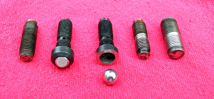 I liked the idea of the internal oiling hole on the ball foot adjuster, but when I cut one open, I see that the ball will seat in the spherical chamber, and choke off much of the oil flow down the screw. Two on the right are where I experimented with adding relief for additional oiling. I filed an annular groove to distribute the oil around the screw body, and then flattened the threads with a file to increase the clearance between them and their female mates. This is the idea, but in the final version, I didn't break the peaks of the threads nearly this much--- 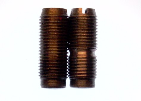 I ended up using 10mm brand new VW adjuster screws. At $12 each from VW, they cost almost as much as my lifters! At one time, I was thinking of using 911 elephant feet. I even bought a set of 8mm rockers. But I was afraid that with zero lash the valve tip wouldn't be exposed for adequate lube. So I went with the stock. Anyway, as for adjustments- I got these very very close to perfect geometry at +1 turn from zero lash. This was done using the blue dye method I described earlier. Now I am driving it for a while. At probably 2000 miles, I will pull the rocker shafts, cylinder by cylinder, and look at the wear pattern on the adjuster screws. Even without the dye, it shows up as a bright line. If it's centered, I'll just put them back in as a set and go on to the next. If it's skewed away from the shaft, I'll tighten it in 1/4 turn, set the lock nut, reinstall, and move on. If it's skewed outboard from the shaft, I'll loosen it 1/4 turn and so on. The lesson learned here- WHEN YOU ADJUST THE VALVES ON A SOLID LIFTER ENGINE, YOU'RE SETTING THE CLEARANCE. ON A HYDRO YOU'RE SETTING THE VALVE GEOMETRY. I can comfortably go another 1/4 turn (1/2 total in either direction from my 1 turn starting point). I'll keep a log, so I'll know if I went your first 1/4 turn already or not, and also so I can see if it's stabilizing or if something is changing- like a valve is sinking into the head. I'm thinking it should stabilize after the first setting. Any further drift is more likely that I didn't get it right the first time. Once it's stabilized, I intend to go much longer time between checks- maybe 20000 miles? I don't know, I'll have to see what I see the first few times. If your doing this on your engine, and you have no idea if your geometry is right, just pull the rocker shaft without disturbing the adjuster setting and examine the skid mark on the adjuster. If it's centered, your geometry is good. Reassemble and then check where it's set. Carefully unscrew exactly two full turns, then turn in until you get zero lash. Ideally it will be in about 1 turn. Then reset it to where it was and you're done. Log the setting. If it's not centered, then just set them at zero plus 1 turn, and drive it 1000-2000 miles and check again. If you can't get it centered and within 1/2 - 1.5 turns lash, your pushrods are too short or too long.... you take it from there... So that's it. And how's it running? GREAT! It really sings! Starts instantly, idles smooth, pulls strong- especially from 4000-5000 RPM. When I stop at a light, I can actually hear the air being sucked in the air cleaner (stock). The Bursch exhaust is very much cleaner sounding than before. All in all, worth the effort. If anyone else already owns a hydro 914, or is thinking of maybe trying it, I hope this writeup gets you thinking about everything that is going on in there- it alway helps to know how something works before you get in and start changing it. |
|
|
|
Posts in this topic
jk76.914 New views on hydraulic cams. Jul 15 2007, 06:24 PM Dave_Darling Interesting... IIRC, lack of rocker (and associat... Jul 15 2007, 07:59 PM McMark Thanks! Looking forward to the rest of the ... Jul 15 2007, 08:08 PM 914Sixer Very interesting article. I just pulled apart a 1... Jul 15 2007, 08:56 PM
 jk76.914
Very interesting article. I just pulled apart a ... Jul 16 2007, 05:09 AM sww914 Very interesting post. Thanks for doing all the re... Jul 15 2007, 09:43 PM Jake Raby A large portuion of the problem with Hydro equippe... Jul 16 2007, 06:02 AM Johny Blackstain :popcorn: !
I am no mechanical engineer but ... Jul 16 2007, 06:26 AM jk76.914
:popcorn: !
I am no mechanical engineer but... Jul 17 2007, 01:04 PM jk76.914
:popcorn: !
I am no mechanical engineer but... Jul 18 2007, 09:12 PM Johny Blackstain
Forget to reply to the Mercedes injectors- they... Jul 18 2007, 09:16 PM Jake Raby Yes, I have purposely neglected my engines for the... Jul 16 2007, 06:44 AM rjames jk76.914, your timing is perfect.
I have hydros i... Jul 16 2007, 03:21 PM Jake Raby Loud hydros are usually due to oil pressure issues... Jul 16 2007, 03:33 PM jk76.914 Thanks for all the replies. I wanted to get into ... Jul 16 2007, 07:14 PM Bleyseng Hell, I have always thought with the head half ful... Jul 16 2007, 07:37 PM jk76.914
Hell, I have always thought with the head half fu... Jul 16 2007, 08:43 PM Jake Raby When all your oil ends up in the valve covers and ... Jul 16 2007, 07:44 PM jk76.914
When all your oil ends up in the valve covers and... Jul 16 2007, 08:43 PM jk76.914 Thanks for all the replies. I wanted to get into ... Jul 16 2007, 08:39 PM Jake Raby One thing to consider is the fact that adding thos... Jul 16 2007, 08:43 PM jk76.914
One thing to consider is the fact that adding tho... Jul 16 2007, 08:55 PM Jake Raby Solid lifters do not rely on oil pressure to funct... Jul 16 2007, 09:01 PM rjames What weight of oil and type (synthetic or non) is ... Jul 17 2007, 02:04 AM jk76.914
What weight of oil and type (synthetic or non) is... Jul 17 2007, 05:33 AM Jake Raby You need to change that oil every 3 months, even i... Jul 17 2007, 08:43 AM SGB I use 20W50 Castrol changed every few months with ... Jul 17 2007, 08:18 PM morph I have started to experiment with motors,and to ha... Jul 17 2007, 11:26 PM 914-8 I did some similar research regarding hydraulic li... Jul 18 2007, 10:15 PM jk76.914
I did some similar research regarding hydraulic l... Jul 19 2007, 04:58 PM Jake Raby My opinion is that having hydraulic adjustment imp... Jul 18 2007, 10:18 PM jk76.914 I'll try and finish up my brain dump tonight. ... Jul 19 2007, 05:00 PM MecGen Hey
Man....serious good work here ! :popcorn... Jul 21 2007, 06:02 AM jk76.914
Hey
Man....serious good work here ! :popcor... Jul 21 2007, 08:43 AM Dr Evil Very cool and concise write up, thanks! :thumb... Jul 21 2007, 11:20 AM Coy
I have a 2 liter with hydraulic lifters & tw... Jul 21 2007, 05:58 PM MecGen Hah
I knew you were a hightec type of guy :DRUNK... Jul 22 2007, 07:03 AM jk76.914
Hah
I knew you were a hightec type of guy :DRUN... Jul 22 2007, 10:05 AM
jk76.914
Very interesting article. I just pulled apart a ... Jul 16 2007, 05:09 AM sww914 Very interesting post. Thanks for doing all the re... Jul 15 2007, 09:43 PM Jake Raby A large portuion of the problem with Hydro equippe... Jul 16 2007, 06:02 AM Johny Blackstain :popcorn: !
I am no mechanical engineer but ... Jul 16 2007, 06:26 AM jk76.914
:popcorn: !
I am no mechanical engineer but... Jul 17 2007, 01:04 PM jk76.914
:popcorn: !
I am no mechanical engineer but... Jul 18 2007, 09:12 PM Johny Blackstain
Forget to reply to the Mercedes injectors- they... Jul 18 2007, 09:16 PM Jake Raby Yes, I have purposely neglected my engines for the... Jul 16 2007, 06:44 AM rjames jk76.914, your timing is perfect.
I have hydros i... Jul 16 2007, 03:21 PM Jake Raby Loud hydros are usually due to oil pressure issues... Jul 16 2007, 03:33 PM jk76.914 Thanks for all the replies. I wanted to get into ... Jul 16 2007, 07:14 PM Bleyseng Hell, I have always thought with the head half ful... Jul 16 2007, 07:37 PM jk76.914
Hell, I have always thought with the head half fu... Jul 16 2007, 08:43 PM Jake Raby When all your oil ends up in the valve covers and ... Jul 16 2007, 07:44 PM jk76.914
When all your oil ends up in the valve covers and... Jul 16 2007, 08:43 PM jk76.914 Thanks for all the replies. I wanted to get into ... Jul 16 2007, 08:39 PM Jake Raby One thing to consider is the fact that adding thos... Jul 16 2007, 08:43 PM jk76.914
One thing to consider is the fact that adding tho... Jul 16 2007, 08:55 PM Jake Raby Solid lifters do not rely on oil pressure to funct... Jul 16 2007, 09:01 PM rjames What weight of oil and type (synthetic or non) is ... Jul 17 2007, 02:04 AM jk76.914
What weight of oil and type (synthetic or non) is... Jul 17 2007, 05:33 AM Jake Raby You need to change that oil every 3 months, even i... Jul 17 2007, 08:43 AM SGB I use 20W50 Castrol changed every few months with ... Jul 17 2007, 08:18 PM morph I have started to experiment with motors,and to ha... Jul 17 2007, 11:26 PM 914-8 I did some similar research regarding hydraulic li... Jul 18 2007, 10:15 PM jk76.914
I did some similar research regarding hydraulic l... Jul 19 2007, 04:58 PM Jake Raby My opinion is that having hydraulic adjustment imp... Jul 18 2007, 10:18 PM jk76.914 I'll try and finish up my brain dump tonight. ... Jul 19 2007, 05:00 PM MecGen Hey
Man....serious good work here ! :popcorn... Jul 21 2007, 06:02 AM jk76.914
Hey
Man....serious good work here ! :popcor... Jul 21 2007, 08:43 AM Dr Evil Very cool and concise write up, thanks! :thumb... Jul 21 2007, 11:20 AM Coy
I have a 2 liter with hydraulic lifters & tw... Jul 21 2007, 05:58 PM MecGen Hah
I knew you were a hightec type of guy :DRUNK... Jul 22 2007, 07:03 AM jk76.914
Hah
I knew you were a hightec type of guy :DRUN... Jul 22 2007, 10:05 AM |
5 User(s) are reading this topic (5 Guests and 0 Anonymous Users)
0 Members:

|
Lo-Fi Version | Time is now: 14th March 2025 - 11:56 AM |
Invision Power Board
v9.1.4 © 2025 IPS, Inc.