|
|
|
Porsche, and the Porsche crest are registered trademarks of Dr. Ing. h.c. F. Porsche AG.
This site is not affiliated with Porsche in any way. Its only purpose is to provide an online forum for car enthusiasts. All other trademarks are property of their respective owners. |
|
|

  |

| Jake Raby |
 Mar 16 2010, 07:08 PM Mar 16 2010, 07:08 PM
Post
#21
|
|
Engine Surgeon  Group: Members Posts: 9,394 Joined: 31-August 03 From: Lost Member No.: 1,095 Region Association: South East States |
QUOTE(jeffdon @ Mar 16 2010, 08:53 AM)  QUOTE(Jake Raby @ Mar 14 2010, 06:10 PM) I'd expect that you didn't carry out any valvetrain geometry procedures?? I've never seen a 494 come close to optimizing with a stock length pushrod. The 494 has a fast ramp, it must have geometry carried out to prevent valvetrain wear, especially valve guides. I did a dry assembly and did a quick and dirty visual check of the adjuster/pushrod relation, and it looked pretty well aligned throughout its cycle. Then again, i only looked at one cylinder and just assumed that it would be the same for all others. Probably hosed myself on that one, but at this point, I dont think i want to pull her apart again. ....a visual? How about a measurement of actual values? You have made an alteration of the camshaft, and probably after 30+ years at least 6 more of the 11 variables that can directly impact valvetrain are present within your engine combination. So you must follow a specific procedure to MEASURE these things and then ensure that the proper set up is carried out. Otherwise you'll wonder why the engine sounds like diesel, eats valve guides and requires constant valve adjustments. The web 494 is a cam with some aggressive ramps and due to that its hard on valve train components. |
   |

 
|
| VaccaRabite |
Mar 16 2010, 09:19 PM
Post
#22
|
|
En Garde! Group: Admin Posts: 13,469 Joined: 15-December 03 From: Dallastown, PA Member No.: 1,435 Region Association: MidAtlantic Region |
QUOTE(brant @ Mar 16 2010, 06:21 PM) Zach, I apologize for not using the search feature I'm sure that Jake covers this very well on his site somewhere also. but do you have a link to the correct procedure I need to learn this tia brant I have it saved somewhere at work. But if you search for it over on Jakes site you will find it. He wrote it. Zach |
 |
|
| jeffdon |
Mar 17 2010, 09:19 AM
Post
#23
|
|
Senior Member Group: Members Posts: 1,094 Joined: 24-October 06 From: oakland, ca Member No.: 7,087 Region Association: None |
Allrighty, will devise a nice mount for my dial indicator and check it more carefully. Just one more thing to keep me from actually putting the engine it. Which of course, means I can delay prepping and painting the engine bay. And thats a good thing, as i hate paint prep.
|
|
|
|
| jeffdon |
Mar 20 2010, 01:45 PM
Post
#24
|
|
Senior Member Group: Members Posts: 1,094 Joined: 24-October 06 From: oakland, ca Member No.: 7,087 Region Association: None |
Allrighty, check it out. No 3 exhaust, half way though travel. My cam spec is .465 lift, both ex. and intake....i am getting .446, which is under 5% variation. By my eye, the adjuster/valve orientation looks good. What do ya'll think? This is Stock push rods, P/C are 96mm (not sure on the height).
Should I go with it? Do I have to check all the other valves since the lift spec is same for Exhaust and intake? OOPS.....forgot the pic...think the angle of my DI could be too great for accuracy? .  |
|
|
|
| McMark |
Mar 20 2010, 02:58 PM
Post
#25
|
|
914 Freak! Group: Retired Admin Posts: 20,179 Joined: 13-March 03 From: Grand Rapids, MI Member No.: 419 Region Association: None |
Attached image(s) 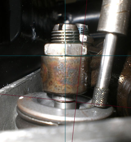
|
|
|
|
| jeffdon |
Mar 20 2010, 03:27 PM
Post
#26
|
|
Senior Member Group: Members Posts: 1,094 Joined: 24-October 06 From: oakland, ca Member No.: 7,087 Region Association: None |
QUOTE(McMark @ Mar 20 2010, 01:58 PM) Too far out to run as is? Also, I did not set to zero lash as Jake recommends in his art. on the topic. I think that would narrow the angle. But would not you rather be looking at the real world angle as it will be set ? And THANKS! What program are you using to draw the lines? |
|
|
|
| brant |
Mar 20 2010, 06:18 PM
Post
#27
|
|
914 Wizard Group: Members Posts: 11,641 Joined: 30-December 02 From: Colorado Member No.: 47 Region Association: Rocky Mountains |
Jeff,
any chance you have a link to the article? I've still been too lazy to go searching brant |
|
|
|
| Jake Raby |
Mar 20 2010, 08:05 PM
Post
#28
|
|
Engine Surgeon Group: Members Posts: 9,394 Joined: 31-August 03 From: Lost Member No.: 1,095 Region Association: South East States |
The procedure should be done at zero lash. Also, the web 494 has a ramp speed thats fast enough to kill valve adjusters unless they are swivel feet.
Adding cam without upgrading THE ENTIRE valve train is a nasty mistake.. Those stock adjusters will be hating life. And those stock retainers were barely acceptable for a stock camshaft... Those are the reasons why I only sell valve train kits... |
|
|
|
| jeffdon |
Mar 21 2010, 01:16 PM
Post
#29
|
|
Senior Member Group: Members Posts: 1,094 Joined: 24-October 06 From: oakland, ca Member No.: 7,087 Region Association: None |
Not to question your experience, Jake, of which i have utmost respect. Just trying to learn.
If your valve adj. and valve stem are in perfect alignment at mid stroke, seem like your going to be out of alignment for the rest of the stroke either before or after the midpoint. Doesnt this also cause loading on the valve? IE in Marks drawings as the adjuster comes down, seems like the top of the blue line would move left. As it goes up, it the top would swing closer to the redline, right? |
|
|
|
| Jake Raby |
Mar 21 2010, 01:27 PM
Post
#30
|
|
Engine Surgeon Group: Members Posts: 9,394 Joined: 31-August 03 From: Lost Member No.: 1,095 Region Association: South East States |
QUOTE(jeffdon @ Mar 21 2010, 12:16 PM) Not to question your experience, Jake, of which i have utmost respect. Just trying to learn. If your valve adj. and valve stem are in perfect alignment at mid stroke, seem like your going to be out of alignment for the rest of the stroke either before or after the midpoint. Doesnt this also cause loading on the valve? IE in Marks drawings as the adjuster comes down, seems like the top of the blue line would move left. As it goes up, it the top would swing closer to the redline, right? Yes, but at mid-lift the valve has the most force against the guide, which is what you need to reduce. The very issue you mention is exactly WHY the swivel foot valve adjuster is such a worthy upgrade. Follow the procedure I outlined, its the same procedure that most all builders follow, not just me. I do this with every engine I build, from 36 HP to over 500 HP roller turbo engines. This procedure when used in our FP race engine keeps valve guides in service for two seasons of 9,000 RPM operation. It works. |
|
|
|
| jeffdon |
Mar 21 2010, 01:54 PM
Post
#31
|
|
Senior Member Group: Members Posts: 1,094 Joined: 24-October 06 From: oakland, ca Member No.: 7,087 Region Association: None |
QUOTE(Jake Raby @ Mar 21 2010, 12:27 PM) QUOTE(jeffdon @ Mar 21 2010, 12:16 PM) Not to question your experience, Jake, of which i have utmost respect. Just trying to learn. If your valve adj. and valve stem are in perfect alignment at mid stroke, seem like your going to be out of alignment for the rest of the stroke either before or after the midpoint. Doesnt this also cause loading on the valve? IE in Marks drawings as the adjuster comes down, seems like the top of the blue line would move left. As it goes up, it the top would swing closer to the redline, right? Yes, but at mid-lift the valve has the most force against the guide, which is what you need to reduce. The very issue you mention is exactly WHY the swivel foot valve adjuster is such a worthy upgrade. Follow the procedure I outlined, its the same procedure that most all builders follow, not just me. I do this with every engine I build, from 36 HP to over 500 HP roller turbo engines. This procedure when used in our FP race engine keeps valve guides in service for two seasons of 9,000 RPM operation. It works. Thanks for the (continuing) education! |
|
|
|
| rtalich |
Mar 22 2010, 12:47 PM
Post
#32
|
|
Member Group: Members Posts: 279 Joined: 25-September 06 From: Bellevue, WA Member No.: 6,913 Region Association: None |
QUOTE(jeffdon @ Mar 20 2010, 12:45 PM) Allrighty, check it out. No 3 exhaust, half way though travel. My cam spec is .465 lift, both ex. and intake....i am getting .446, which is under 5% variation. By my eye, the adjuster/valve orientation looks good. What do ya'll think? This is Stock push rods, P/C are 96mm (not sure on the height). Should I go with it? Do I have to check all the other valves since the lift spec is same for Exhaust and intake? OOPS.....forgot the pic...think the angle of my DI could be too great for accuracy? . Is this pic supposed to be showing 1/2 lift or full? Above you say half way thru travel... to me that implies 1/2 lift. If thats the case how are you measuring .446 at half lift? If .446 is what you get at full lift, then your half lift number will be .223. Thats where everything should be lined up. Hope this helps. |
|
|
|
| jeffdon |
Mar 24 2010, 09:18 AM
Post
#33
|
|
Senior Member Group: Members Posts: 1,094 Joined: 24-October 06 From: oakland, ca Member No.: 7,087 Region Association: None |
QUOTE(rtalich @ Mar 22 2010, 11:47 AM) QUOTE(jeffdon @ Mar 20 2010, 12:45 PM) Allrighty, check it out. No 3 exhaust, half way though travel. My cam spec is .465 lift, both ex. and intake....i am getting .446, which is under 5% variation. By my eye, the adjuster/valve orientation looks good. What do ya'll think? This is Stock push rods, P/C are 96mm (not sure on the height). Should I go with it? Do I have to check all the other valves since the lift spec is same for Exhaust and intake? OOPS.....forgot the pic...think the angle of my DI could be too great for accuracy? . Is this pic supposed to be showing 1/2 lift or full? Above you say half way thru travel... to me that implies 1/2 lift. If thats the case how are you measuring .446 at half lift? If .446 is what you get at full lift, then your half lift number will be .223. Thats where everything should be lined up. Hope this helps. Pic is at half lift, .223. |
|
|
|
|
3 User(s) are reading this topic (3 Guests and 0 Anonymous Users)
0 Members:

|
Lo-Fi Version | Time is now: 18th June 2024 - 06:30 AM |
Invision Power Board
v9.1.4 © 2024 IPS, Inc.