|
|

|
Porsche, and the Porsche crest are registered trademarks of Dr. Ing. h.c. F. Porsche AG.
This site is not affiliated with Porsche in any way. Its only purpose is to provide an online forum for car enthusiasts. All other trademarks are property of their respective owners. |
|
|
  |
| Mike Bellis |
 Apr 5 2011, 02:12 PM Apr 5 2011, 02:12 PM
Post
#121
|
|
Resident Electrician      Group: Members Posts: 8,346 Joined: 22-June 09 From: Midlothian TX Member No.: 10,496 Region Association: None 

|
|
| Andyrew |
 Apr 5 2011, 03:03 PM Apr 5 2011, 03:03 PM
Post
#122
|
|
Spooling.... Please wait           Group: Members Posts: 13,377 Joined: 20-January 03 From: Riverbank, Ca Member No.: 172 Region Association: Northern California 
|
Thats a nice looking setup! Dont quite understand filling the tube with grease though. Link to the joints?
And again. I like orange (IMG:style_emoticons/default/smile.gif) |
| Mike Bellis |
 Apr 8 2011, 08:04 PM Apr 8 2011, 08:04 PM
Post
#123
|
|
Resident Electrician      Group: Members Posts: 8,346 Joined: 22-June 09 From: Midlothian TX Member No.: 10,496 Region Association: None 

|
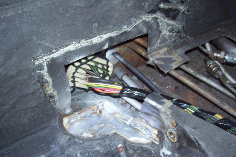
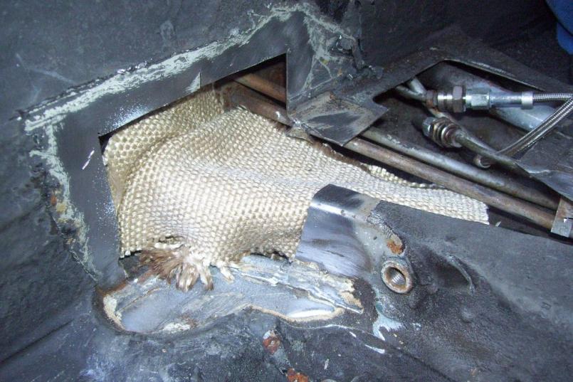
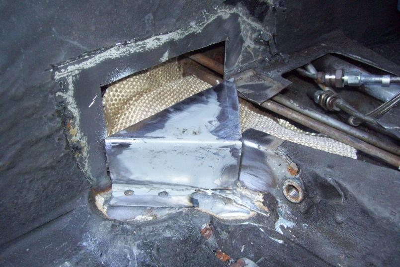
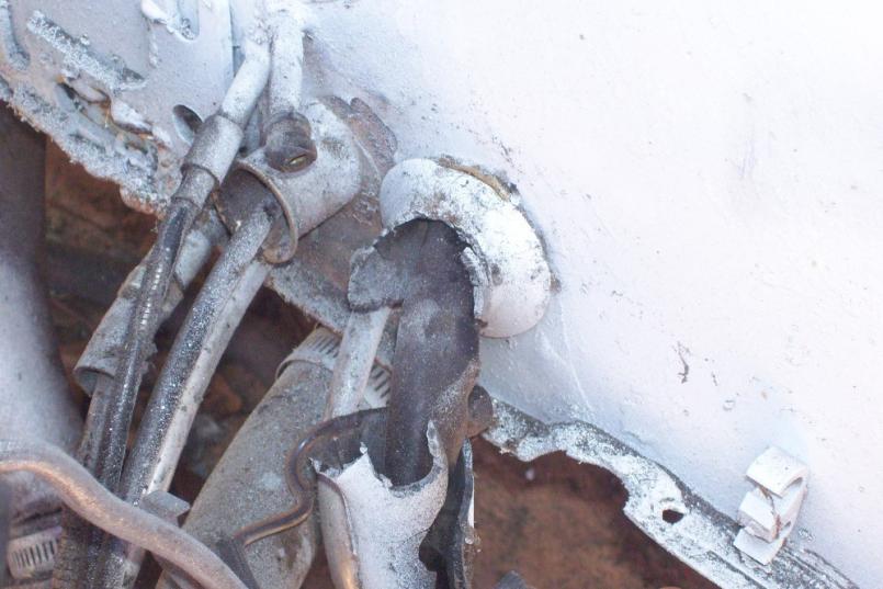
Today I tackled the wiring a little. I removed my engine tray, since I don't need it. It left my bulkhead wiring exposed and looking like crap. I decided on a bulkhead connector like a modern car. I'm sure Project Anklebiter will go with a similar system. Here is the before pic. Old factory 914 broken grommet...
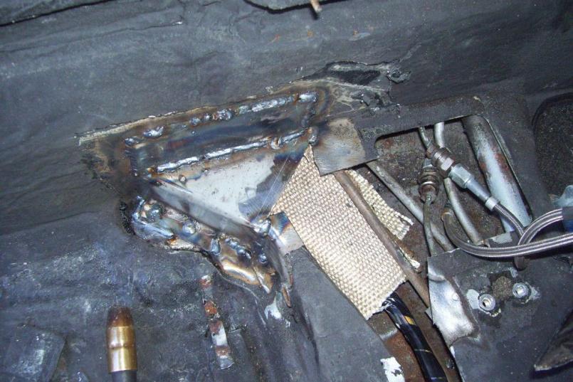
 Here is the after pic. Simple, weatherproof bulkhead connector. This alows me to remove the rear harness and get it out of the way during fabrication. 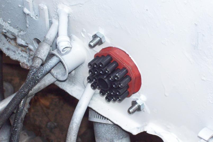 |
| JRust |
 Apr 8 2011, 08:07 PM Apr 8 2011, 08:07 PM
Post
#124
|
|
914 Guru      Group: Members Posts: 6,310 Joined: 10-January 03 From: Corvallis Oregon Member No.: 129 Region Association: Pacific Northwest 
|
(IMG:style_emoticons/default/biggrin.gif) Keep it up Mike! Looking great (IMG:style_emoticons/default/aktion035.gif)
|
| Mike Bellis |
 Apr 8 2011, 08:07 PM Apr 8 2011, 08:07 PM
Post
#125
|
|
Resident Electrician      Group: Members Posts: 8,346 Joined: 22-June 09 From: Midlothian TX Member No.: 10,496 Region Association: None 

|
|
| Mike Bellis |
 Apr 8 2011, 08:10 PM Apr 8 2011, 08:10 PM
Post
#126
|
|
Resident Electrician      Group: Members Posts: 8,346 Joined: 22-June 09 From: Midlothian TX Member No.: 10,496 Region Association: None 

|
|
| Mike Bellis |
 Apr 8 2011, 08:14 PM Apr 8 2011, 08:14 PM
Post
#127
|
|
Resident Electrician      Group: Members Posts: 8,346 Joined: 22-June 09 From: Midlothian TX Member No.: 10,496 Region Association: None 

|
|
| Mike Bellis |
 Apr 8 2011, 08:19 PM Apr 8 2011, 08:19 PM
Post
#128
|
|
Resident Electrician      Group: Members Posts: 8,346 Joined: 22-June 09 From: Midlothian TX Member No.: 10,496 Region Association: None 

|
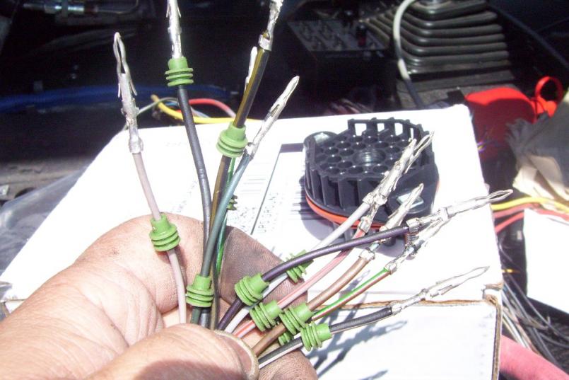
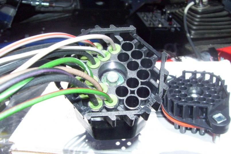
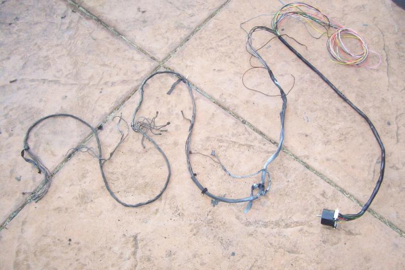
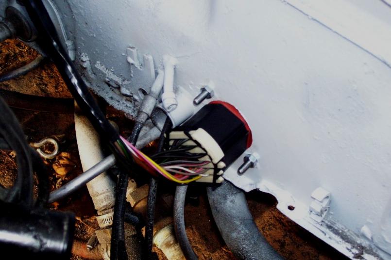
I removed the large red wires from the harness. The ones that connect to the battery and alternator. My battery is in the front, so I pulled the red wires back to the fuse panel. I will route them to the battery up front. When I was done with the 914 wires, I had 8 empty positions. I filled them with spare wires. I will use them for something I'm sure... Notice in this picture, the starter wire was split, shrink tubed and crimped to 2 connectors. This is an acceptible method of making larger wires fit in smaller connectors. I will use a relay in the back to make sure I don't over heat the connection...
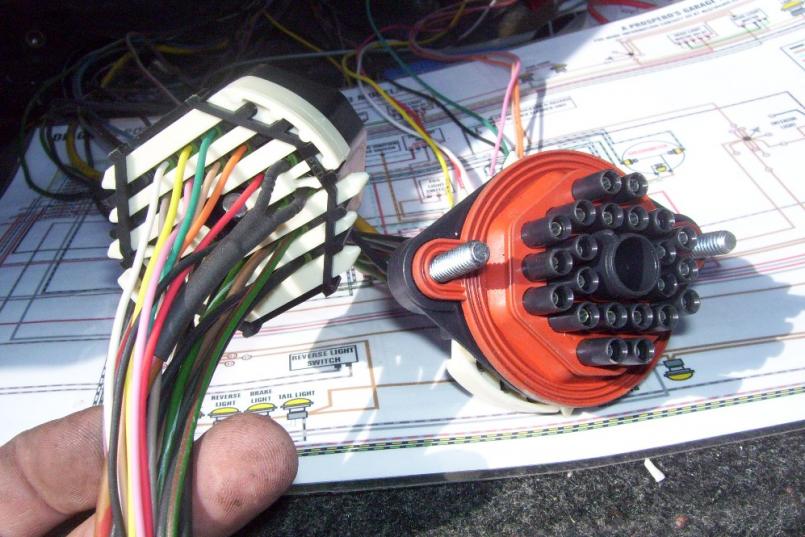 I plugged them together to amke sure all the wires match up... 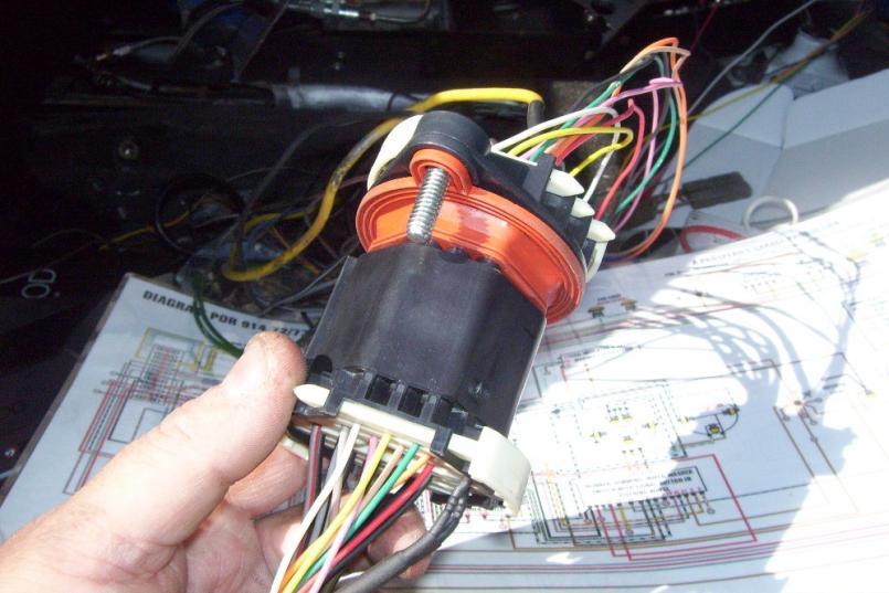 |
| Mike Bellis |
 Apr 8 2011, 08:26 PM Apr 8 2011, 08:26 PM
Post
#129
|
|
Resident Electrician      Group: Members Posts: 8,346 Joined: 22-June 09 From: Midlothian TX Member No.: 10,496 Region Association: None 

|
|
| quadracerx |
 Apr 8 2011, 08:36 PM Apr 8 2011, 08:36 PM
Post
#130
|
|
Member   Group: Members Posts: 427 Joined: 3-July 06 From: WA Member No.: 6,366 Region Association: Pacific Northwest |
Cool...nice job... (IMG:style_emoticons/default/aktion035.gif) DUDE! where did you get the crimps, and crimping tool....LOL?
Thanks... Steve |
| Mike Bellis |
 Apr 8 2011, 08:39 PM Apr 8 2011, 08:39 PM
Post
#131
|
|
Resident Electrician      Group: Members Posts: 8,346 Joined: 22-June 09 From: Midlothian TX Member No.: 10,496 Region Association: None 

|
Cool...nice job... (IMG:style_emoticons/default/aktion035.gif) DUDE! where did you get the crimps, and crimping tool....LOL? Thanks... Steve The crimps come with the bulkhead connector kit (eBay). The crimper I have had for 15 years, from when I needed it for work. |
| Andyrew |
 Apr 9 2011, 06:56 PM Apr 9 2011, 06:56 PM
Post
#132
|
|
Spooling.... Please wait           Group: Members Posts: 13,377 Joined: 20-January 03 From: Riverbank, Ca Member No.: 172 Region Association: Northern California 
|
Figures, the wiring guy would show off his wiring skills ......
Ok im just jealous! That is awesome!!!! Keep up this awesome work!! |
| FourBlades |
 Apr 10 2011, 01:05 PM Apr 10 2011, 01:05 PM
Post
#133
|
|
From Wreck to Rockin     Group: Members Posts: 2,056 Joined: 3-December 07 From: Brevard, FL Member No.: 8,414 Region Association: South East States 
|
I love those weather pac connectors. A great build, this will be an awesome car. Are you going to be ready for summer? John |
| Mike Bellis |
 Apr 10 2011, 01:13 PM Apr 10 2011, 01:13 PM
Post
#134
|
|
Resident Electrician      Group: Members Posts: 8,346 Joined: 22-June 09 From: Midlothian TX Member No.: 10,496 Region Association: None 

|
I love those weather pac connectors. A great build, this will be an awesome car. Are you going to be ready for summer? John If I find a job (got laid off 2 weeks ago) I can have it done by summer. At least be able to drive it and work the bugs out. Then I get to take it apart and paint it. We shall see... Running low on $$$. So I'm doing what I can without spending a lot. |
| FourBlades |
 Apr 10 2011, 01:18 PM Apr 10 2011, 01:18 PM
Post
#135
|
|
From Wreck to Rockin     Group: Members Posts: 2,056 Joined: 3-December 07 From: Brevard, FL Member No.: 8,414 Region Association: South East States 
|
Good luck on your job search. At least you are putting your extra time to good use. You have a lot of unique and inventive things on this car already. John |
| Mike Bellis |
 Apr 14 2011, 05:29 PM Apr 14 2011, 05:29 PM
Post
#136
|
|
Resident Electrician      Group: Members Posts: 8,346 Joined: 22-June 09 From: Midlothian TX Member No.: 10,496 Region Association: None 

|
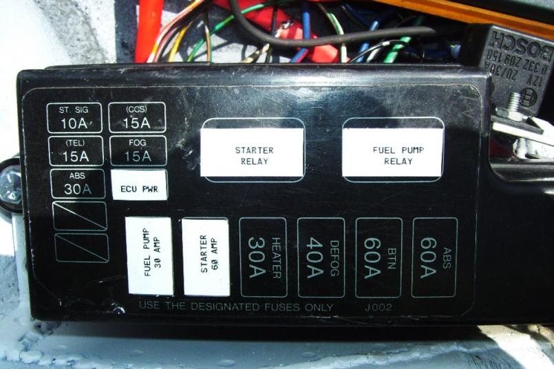
The real wiring challenge has begun. So far I have repaired and modified the rear 914 harness. I have disected the RX7 (Cosmo) harness. I have the ECU harness with it's miryad of wires... (IMG:style_emoticons/default/blink.gif) I decided to use the Mazda engine fuse/relay panel and adaptit to my needs. It satrted by cutting it loose from the main harness and blueprinting the connections. So far I have the fuel pump and starter relays configured and the ECU power fuse. The fuse panel connections were "Hot all the time". I am using 2 Bosch relays as a master ignition control. The Bosch relays turn on the ATC fuses when the ignition is on. The Starter and fuel relays along with the Maxi fuses are Hot all the time and activated only when needed. The ECU will control the fuel pump and I have a power bypass in the cabin if needed. The starter relay is set up just like a hot start kit. I managed to get the engine sensors wired to the engine and routed into the rear trunk; Where all the magic happens. I have not decided on my final spark ignighter setup. The factory uses wasted spark on the Leading spark plugs and discrete spark on the trailing plugs. The ECU should be able to accomplish this but I am considering an MSD. I can use 4 MSD 6AL units and have 4 coils and discrete spark to each plug. This set up would allow finer tuning of the leading and trailing sparks. My budget is very limited now so the MSD will have to wait. I am taking donations. (IMG:style_emoticons/default/biggrin.gif)
Here are some early progress pictures. If you are scared of wires, don't look! In this pic, I have all the wires in the trunk. buried are my note book and Mazda wiring diagram. 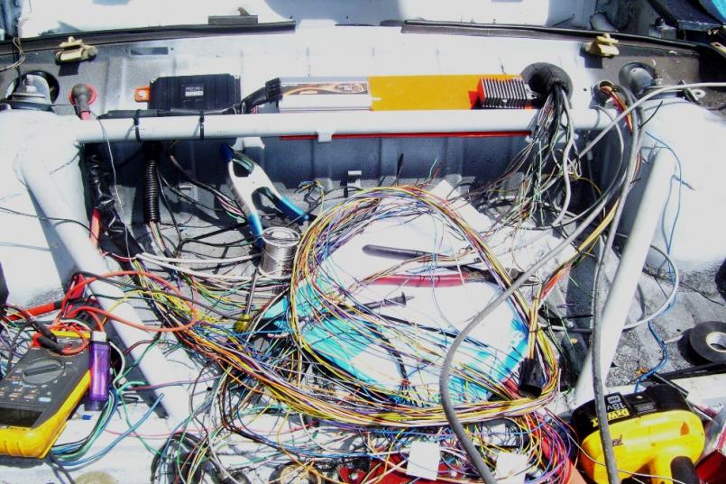 This is the engine with sensor connections in place. The wiring will get dressed up once I know they are correct... 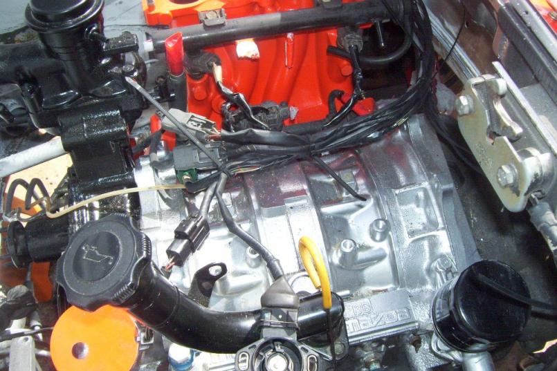 |
| Mike Bellis |
 Apr 14 2011, 05:31 PM Apr 14 2011, 05:31 PM
Post
#137
|
|
Resident Electrician      Group: Members Posts: 8,346 Joined: 22-June 09 From: Midlothian TX Member No.: 10,496 Region Association: None 

|
|
| Mike Bellis |
 Apr 16 2011, 07:50 PM Apr 16 2011, 07:50 PM
Post
#138
|
|
Resident Electrician      Group: Members Posts: 8,346 Joined: 22-June 09 From: Midlothian TX Member No.: 10,496 Region Association: None 

|
Well the ECU is 75% wired up. Still need the gauge wiring to the dash complete and some misc. I took a little break from the ECU and decided to fab up the alternator mount. Since I removed the A/C compressor, Power Steering Pump, Smog Pump and factory alternator it really cleaned up the front of the engine. The old alternator was a saddle mount and my 140 Amp Powermaster is not. So none of the factory stuff would work. I used some 1/4" steel I had laying around and made it to bolt to the existing studs on the engine. There was a massive cast aluminum bracked designe to hold the A/C and steering pump. I looked into modifiying it but it was a piece of shit. The Mazda alt pully was and easy swap from my GM V groove. Same I.D. and thread. I did realize that I don't have the curved tension bracket for my Alt so there will be some more work and a trip to the Junk Yard to pick one up.
So far I have 80 hours into rewiring this car. I under estimated the ammount of fab to go from a V8 to a Rotary. It looked so simple on paper... (IMG:style_emoticons/default/dry.gif) Here's a couple of pics just for fun. Mazda pully fit wo no mods... 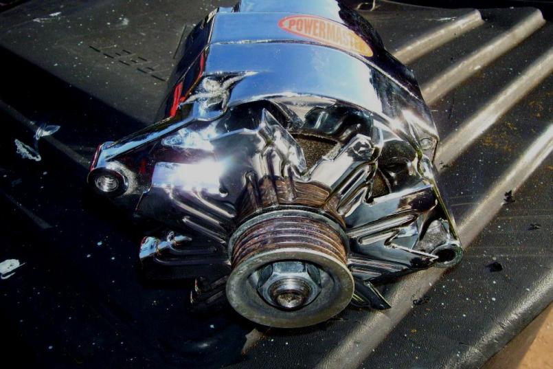 Bracket painted and then I had to clearance the top left bracket a little... 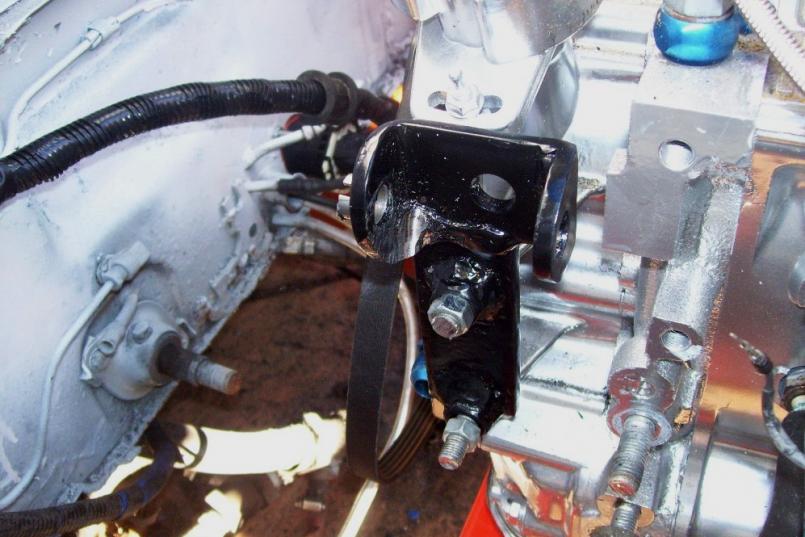 |
| Mike Bellis |
 Apr 16 2011, 07:54 PM Apr 16 2011, 07:54 PM
Post
#139
|
|
Resident Electrician      Group: Members Posts: 8,346 Joined: 22-June 09 From: Midlothian TX Member No.: 10,496 Region Association: None 

|
Here is a pic of the Alt bolted in...
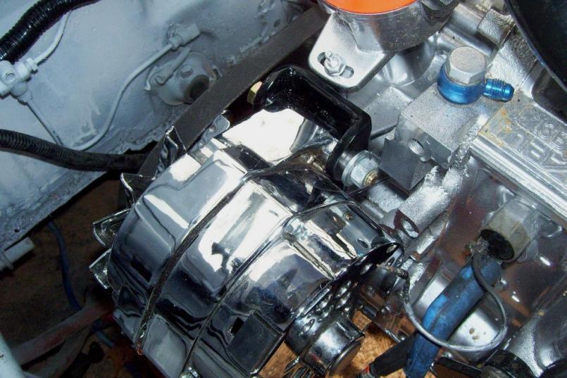 I will post pics of the completed (or as much as can be) in a couple of days. I am still missing some parts but I still have lots that I can do beofre I run out of parts ad money... (IMG:style_emoticons/default/beer3.gif) |
| Andyrew |
 Apr 17 2011, 01:26 AM Apr 17 2011, 01:26 AM
Post
#140
|
|
Spooling.... Please wait           Group: Members Posts: 13,377 Joined: 20-January 03 From: Riverbank, Ca Member No.: 172 Region Association: Northern California 
|
Damn Mike. 80 hours for a guy who does electrical work... That is some serious wiring work. Thats one thing I havent tackled in my car and im not looking forward to...
140amp alternator? You going to run a stereo or do you just like juice? |
  |
6 User(s) are reading this topic (6 Guests and 0 Anonymous Users)
0 Members:

|
Lo-Fi Version | Time is now: 25th November 2024 - 09:45 PM |
Invision Power Board
v9.1.4 © 2024 IPS, Inc.


