|
|
|
Porsche, and the Porsche crest are registered trademarks of Dr. Ing. h.c. F. Porsche AG.
This site is not affiliated with Porsche in any way. Its only purpose is to provide an online forum for car enthusiasts. All other trademarks are property of their respective owners. |
|
|

  |

| nathansnathan |
 Jan 28 2012, 01:24 PM Jan 28 2012, 01:24 PM
Post
#109
|
|
Senior Member  Group: Members Posts: 1,052 Joined: 31-May 10 From: Laguna Beach, CA Member No.: 11,782 Region Association: None |
QUOTE(SirAndy @ Dec 13 2011, 08:01 PM)  QUOTE(nathansnathan @ Dec 13 2011, 06:07 PM) The longs are supposed to be 2 layers of sheet metal from just forward of the seatbelt hole/ jack post all the way back to the top of the inner suspension console. Ok, now i get it. That inner part (with the ribs) was added on later cars, early cars don't have that. (IMG:style_emoticons/default/shades.gif) Actually, no. (IMG:style_emoticons/default/biggrin.gif) I've been thinking about his for awhile, and got distracted some matters with my bus over new years. (IMG:style_emoticons/default/headbang.gif) Sorry to get back so late (IMG:style_emoticons/default/smile.gif) Jeff Hail talks about his in his "Bringing out the dead" thread http://www.914world.com/bbs2/index.php?sho...76791&st=61 QUOTE(Jeff Hail @ Oct 21 2007, 04:37 PM) Where the inner long come's together with the rear frame rail it was double walled by the factory highlited in red. If I were to just weld the inner long to the rear frame rail without the double wall it would be a very flexible joint and eventually fail. This would be compounded by suspension movement and engine weight and torque. This area is where the rear center section of the tub (torque box) ties into the rear structure of the vehicle. This area needs to be as strong or stronger than the factory designed it to be. Everytime the suspension compresses this area is subjected to load. Everytime the vehicle is launched it is subject to load. All of the cars had the same construction in that area. My 71, 72, and the 75 or 76 in the link. Here is his shot of the inner layer of the inner long forward of the firewall. The lower seatbelt bolt threads are welded to that piece. (IMG:http://www.914world.com/bbs2/uploads/post-7712-1193013431.jpg) Attached image(s) 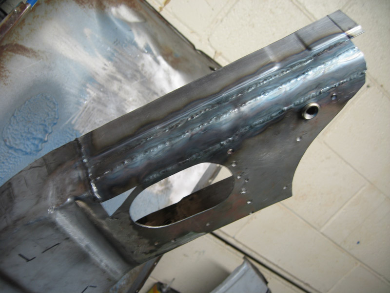
|
   |

 
|
| nathansnathan |
Jan 28 2012, 02:01 PM
Post
#110
|
|
Senior Member Group: Members Posts: 1,052 Joined: 31-May 10 From: Laguna Beach, CA Member No.: 11,782 Region Association: None |
I'd hoped that I'd be posting the attachment of the whole inner piece with my next (this) post, but, well don't get me talking about my bus. (IMG:style_emoticons/default/smile.gif)
Instead, I've just gotten to prepping it for install, almost there. I almost finished the inner layer. I've got to cut that front part where it's marked. I ended up using the shallower corrugations from the outer layer of the parts car in construction of the bottom of the inner forward piece there (accidentally attached to the post above) and the attachment, below. 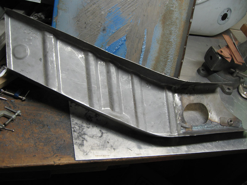 Also, I got the recess for the engine mount handled. 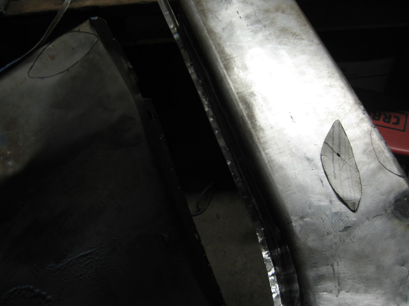 Had to cut into the virgin long. 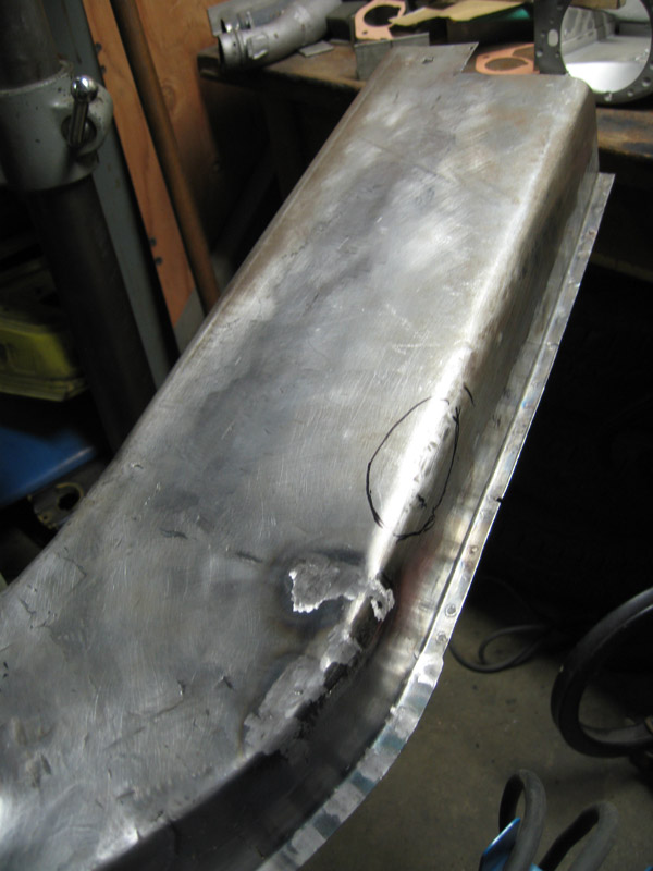 After a lot of comparing, etc to the parts car, 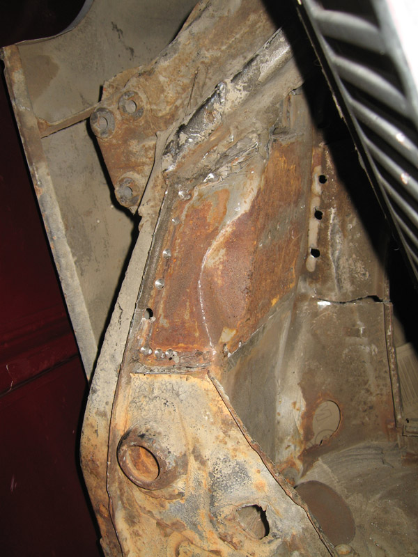 I fit up the inner and outer inner long after cutting a small hole in the outer ( no pic sorry), and ground away using a grinder to get it out to where the template said it should be. 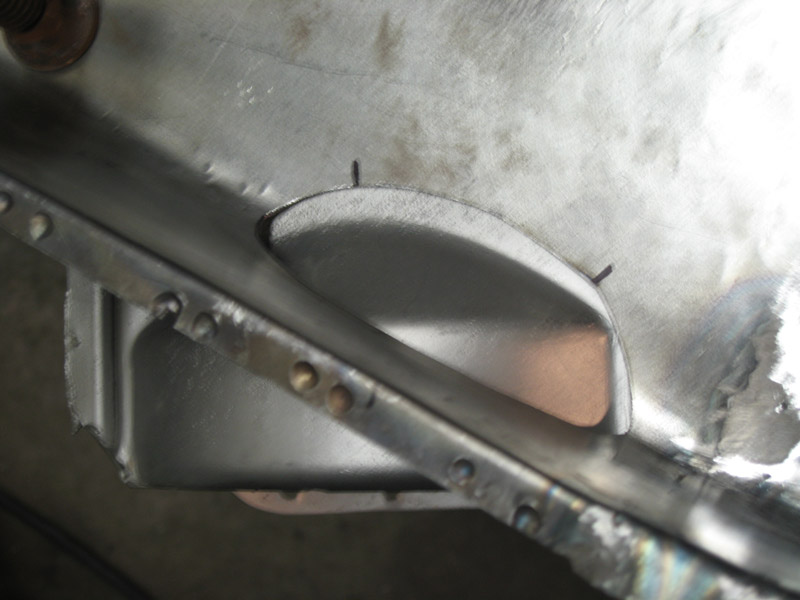 The piece made out of part of my wrinkled door skin, funny how it's creased from the halfway point of 1 side, and then angles, lining up with the arch of the engine mount - hard to explain. (IMG:style_emoticons/default/smile.gif) 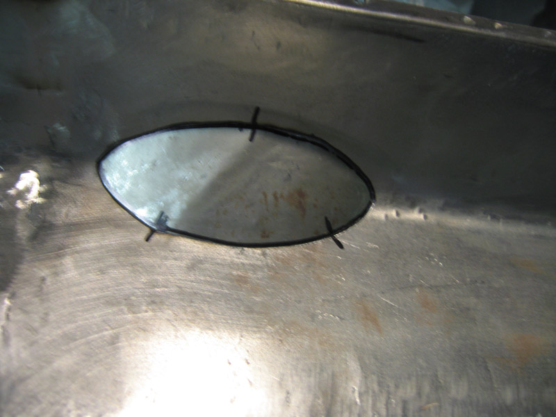 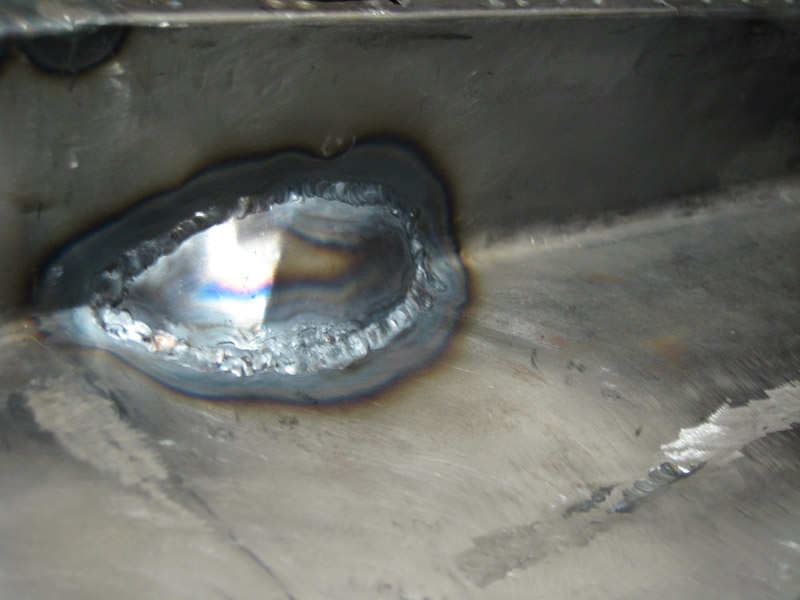 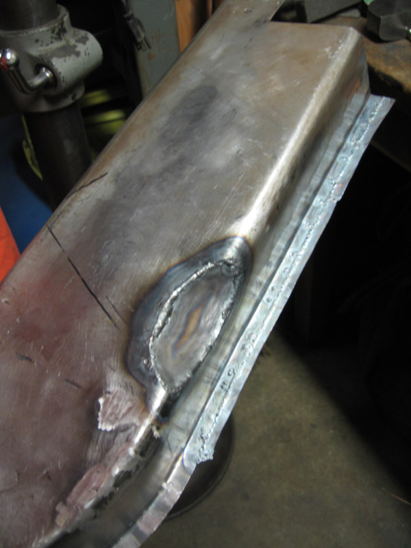 I'm currently out of of grinding/ cutting disks for my mini die grinder to smooth this all out. Yard store has a great price on an Acat pnuematic mini angle grinder. I've just ordered that to step up my grinding smoothing process, along with 2" roloc holders, sanding disks and surface conditioning wheels. It's hard to finish the welds with a straight mini die grinder and then a flap wheel on an electric 4 1/2"angle grinder as I've been doing. ... which is not so precise either to make the flange lips (? not sure about the terminology here) larger. The flanges are larger at the back, and I've been putting off enlarging the ones I've repurposed from the front of the parts car. The difference is small but significant. I had to go bigger to facilitate welding and will trim. I'm still at it actually. 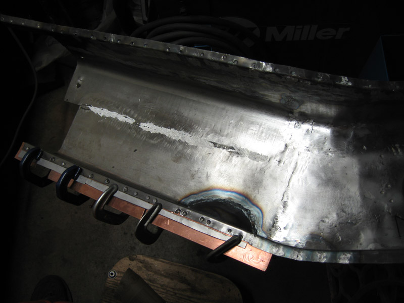 It will require more hammering also; welding brought the top and bottom of the inner in, and the outer is springing out (IMG:style_emoticons/default/smash.gif) I've outlined the inner layer in an adriatic glow. 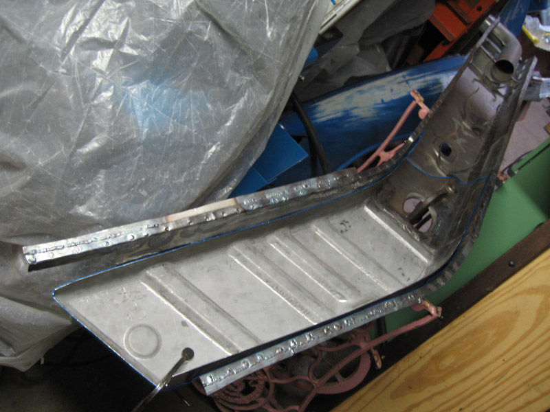 I am thinking that I will put the inner and outer layers of the long together and then put them up to the car, a bit different than how Jeff did it. I feel more comfortable being able to clamp the layers, and to back the welds. Attach the heater tube, the rear heater channel, and put it on. (!) It's a bit more complicated than that...weld thru primer...., actually, but... . The engine mount and inner suspension console will go on after. 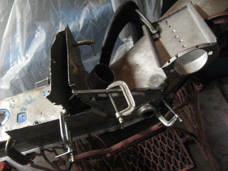 A bit of a fit up. I need to make the bottom of the engine mount, as that is from the drivers side of the donor. A bit of a difference in the upper part on the side, the flange height, but besides that (and the bottom which is symmetrically inverse) they are the same. I need to get some thicker gauge metal to make that. I'd like to have my suspension jig and inner console fitted, engine support bar going to the fitted-up mount, as well as firewall front and rear all in position before welding the inner assembly in. I don't want the bottom of the car to sit too far out and may need to use a tie down strap to pull it together. We'll see soon. 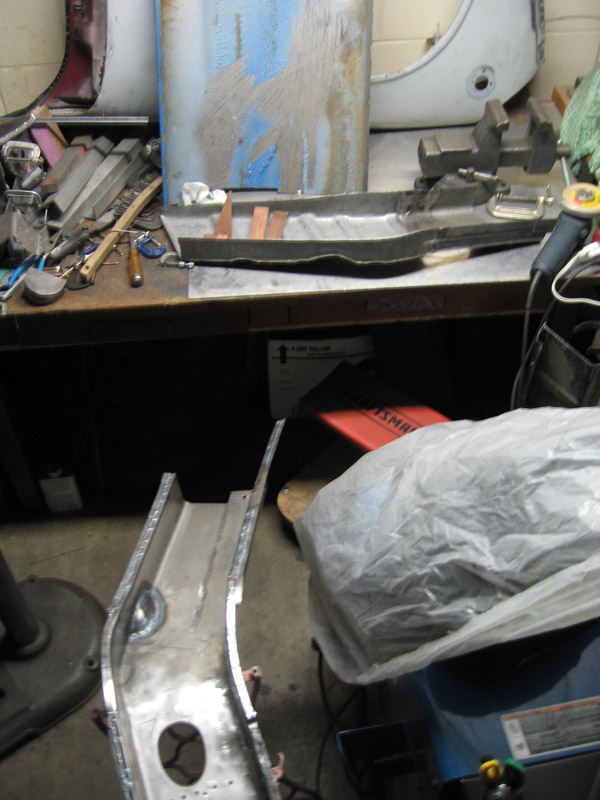 |
|
|
|
| FourBlades |
Jan 28 2012, 05:23 PM
Post
#111
|
|
From Wreck to Rockin Group: Members Posts: 2,056 Joined: 3-December 07 From: Brevard, FL Member No.: 8,414 Region Association: South East States |
Great work as usual. (IMG:style_emoticons/default/smilie_pokal.gif) Your car will be better than new when done. At least the smooth part of the long is the easier one to make of the two, I think a lot of people end up bending something up for that area. John |
|
|
|
| nathansnathan |
Mar 18 2012, 09:33 AM
Post
#112
|
|
Senior Member Group: Members Posts: 1,052 Joined: 31-May 10 From: Laguna Beach, CA Member No.: 11,782 Region Association: None |
I got my outer suspension console back on, finally. Page 3 I'd left with it here
(IMG:http://www.914world.com/bbs2/uploads_offsite/www.914club.com-11782-1301459739.12.jpg) When I took it off, it looked like this (IMG:http://www.914world.com/bbs2/uploads_offsite/www.914club.com-11782-1301459733.3.jpg) Finally got it like this. I couldn't get out all the little black spots back there, but I'm hoping it will be neutralized/ encapsulated by the etching chemicals. 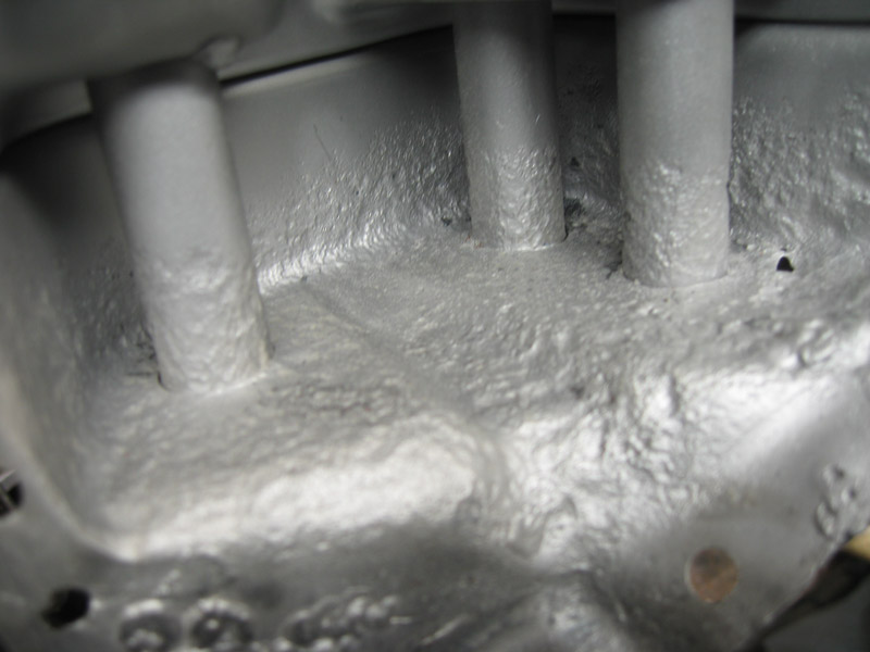 I'd welded up all the carnage from removing it 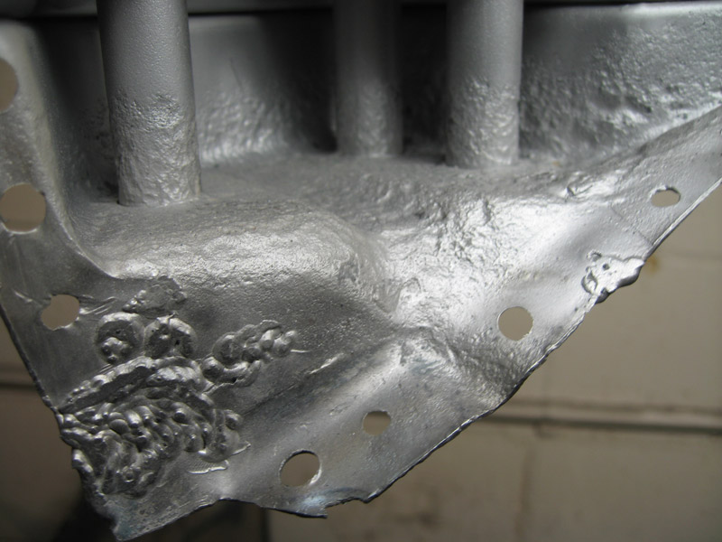 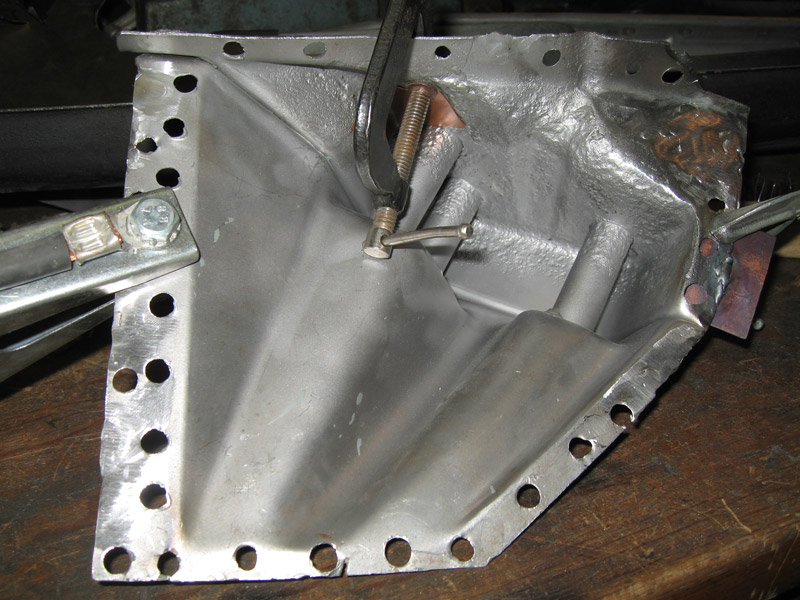 I did the ppg dx579 and dx520. Seems a lot like por's marine clean and metal ready, which I've used before, but maybe stronger even. 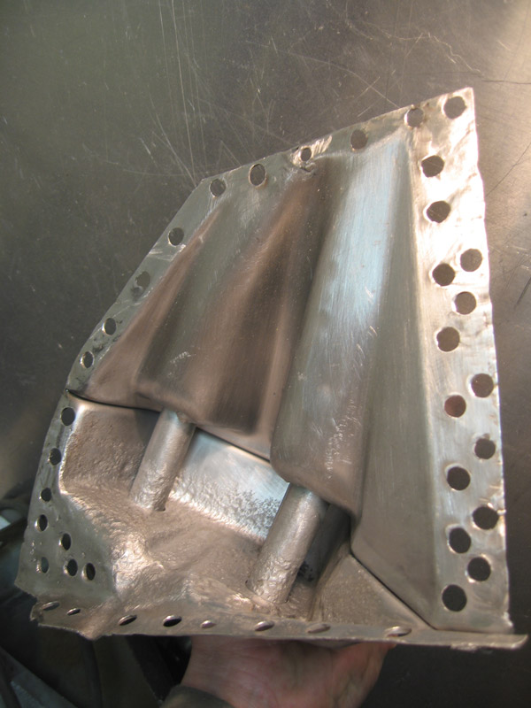 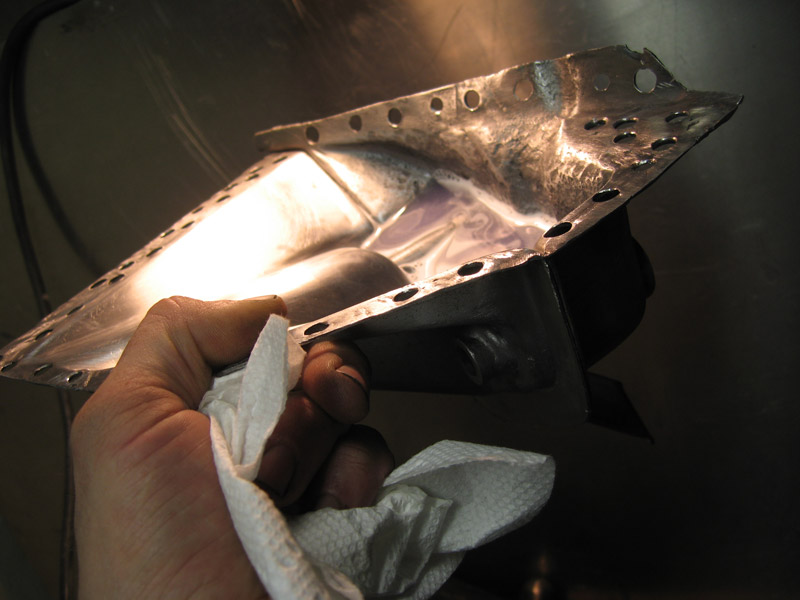 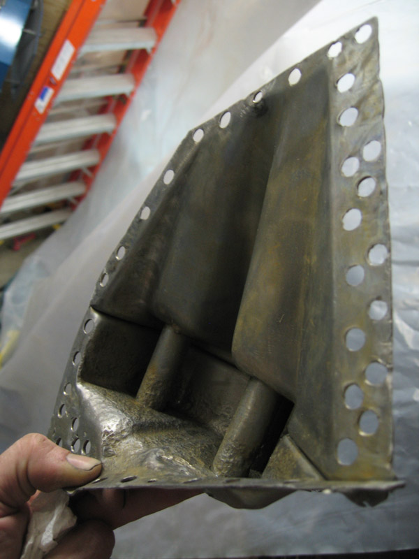 I got a bit rough with the clamp. (IMG:style_emoticons/default/hissyfit.gif) It bothered me for a bit, but I hope it will be ok. It is a learning experience for me here. 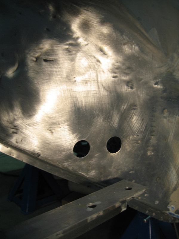 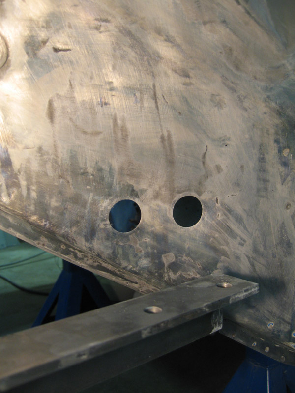 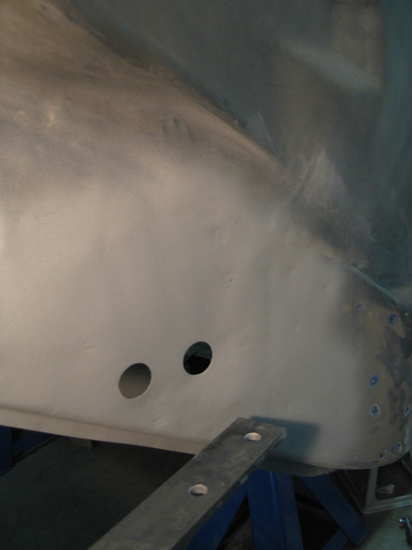 The jig I'd made before removing it. I constructed this to locate the inner suspension console actually. I didn't plan to take the outer off. 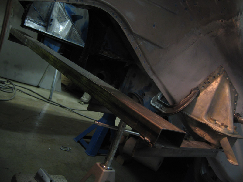 I also measured many times, comparing to the other side. I saw in a recent post, http://www.914world.com/bbs2/index.php?act...=2&t=172145 Rick Ollah, was saying that, (these being hand-built cars), the tolerance for suspension stuff on the bodies is 3mm. I think I got it to 1/16 inch which is 1.5875mm, using a tape measure off the outside of the tops of the bolt receivers (the part that has the clear plastic plugs) It's hard to measure from the bottom where the bolts actually are going. I measured to the nook of the jackpost and receiver plate. I went back to the fender support strap which seems consistent on both sides. I also measured up to the corner of the nook of part of the muffler heat shield. Also, the flange where the top and bottom of the console is 16.5 inches exactly from the bottom of the lip up at the base of the sail, inside. I kind of forget now, but I repositioned it a few times and went from side to side measuring A LOT before I was satisfied. I got it mostly welded in 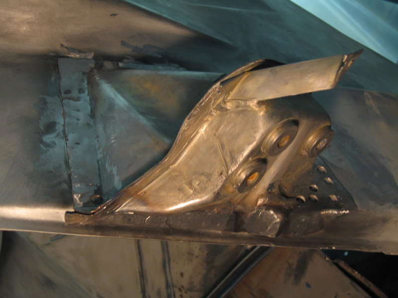 and this is when I got distracted by some blemishes I'd circled earlier on my jack post receiver plate. (IMG:style_emoticons/default/unsure.gif) Not pleased with the results of a screw driver test there. 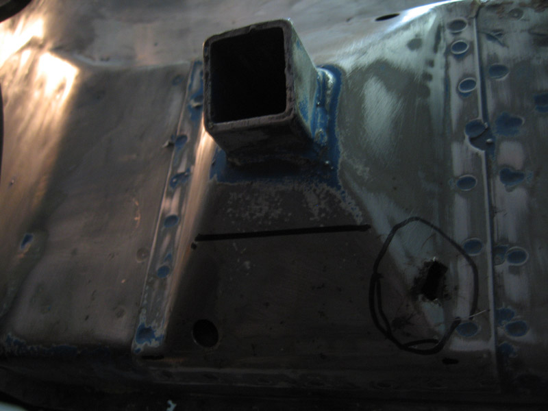 It took me several days to come to grips with this nasty turn of events. My work sent me to Austin for about a week for SXSW film music interactive festival which was awesome. I almost managed to forget about this, but I'm back and after cleaning my shop yesterday, I've gone in again, deeper. Hopefully, I will post soon the resolution of all this. Not only is it not pretty behind the receiver plate, it's not-too-nice I see now between the 2 layers at the bottom, from the front of the plate to where it slants up a foot or so back. (IMG:style_emoticons/default/dry.gif) I've got the metal to fix it, thought I might have had to before, so maybe I can make short work of this. I won't post more pics of it until the sight of what I have done does not induce vomiting. (IMG:style_emoticons/default/icon8.gif) (IMG:style_emoticons/default/icon8.gif) |
|
|
|
| Socalandy |
Mar 18 2012, 09:47 AM
Post
#113
|
|
Its got to be Yellow!!! Group: Members Posts: 2,432 Joined: 29-August 09 From: Orange Member No.: 10,742 Region Association: Southern California |
Amazing work (IMG:style_emoticons/default/aktion035.gif)
|
|
|
|
| nathansnathan |
Jun 22 2012, 11:10 PM
Post
#114
|
|
Senior Member Group: Members Posts: 1,052 Joined: 31-May 10 From: Laguna Beach, CA Member No.: 11,782 Region Association: None |
Wow, it's been 3 months since I've updated. I keep thinking this next post , I will have the long back together (IMG:style_emoticons/default/rolleyes.gif) . I'll get to some of the work I did on that in a post later. For now I'll catch up with the jack point repair.
I didn't get great pics of the first bit, where I'd cut the bottom off, and exposed all the pitting and rust. 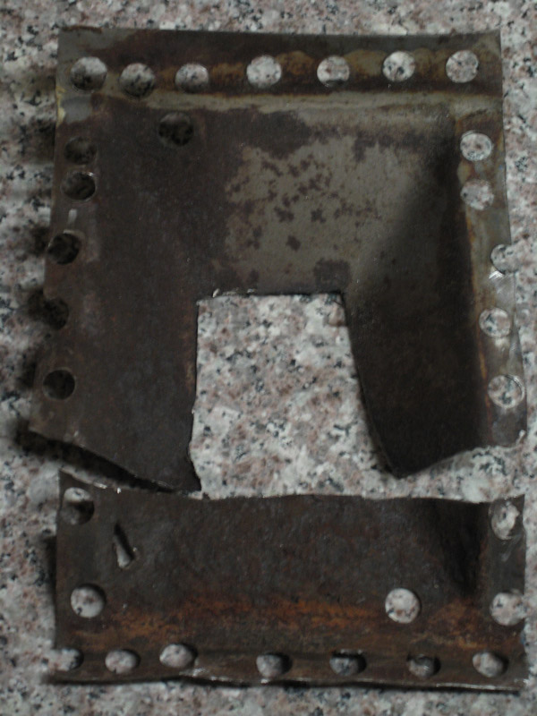 The piece behind the jack plate was pitted pretty good as well, on the outside. I was torn on leaving it, but worried about what might still lie beneath, took it off. 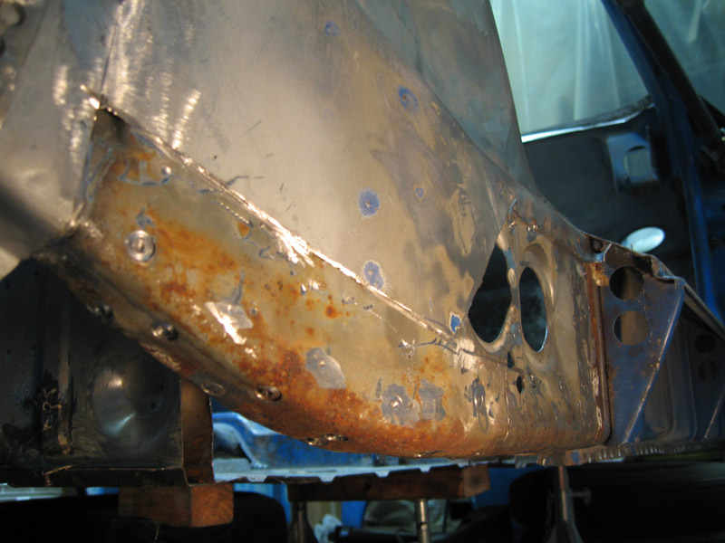 I got it under control with spot blasting and an 80 grit 1 1/2 inch roloc disk on a pnuematic mini right angle grinder. 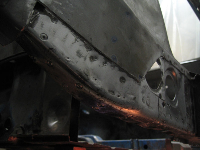 The restoration design piece was, not as ready-to-go-in as I would have liked. The original has a recess stamped in it; the rd piece, just a square hole. The replacement jack post that I ordered (wasn't sure if I'd need it) was like a gauge thinner than the original. I decided to weld the original post into the replacement hole which I made bigger. 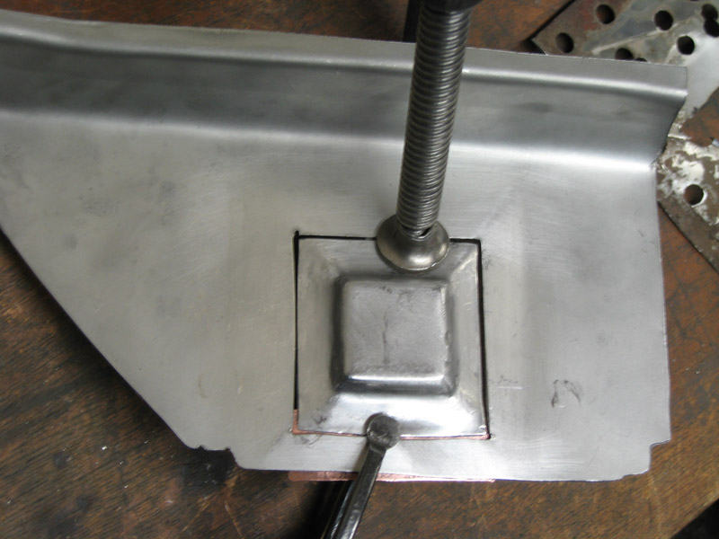 The front, also, was about a half inch short. Attached image(s) 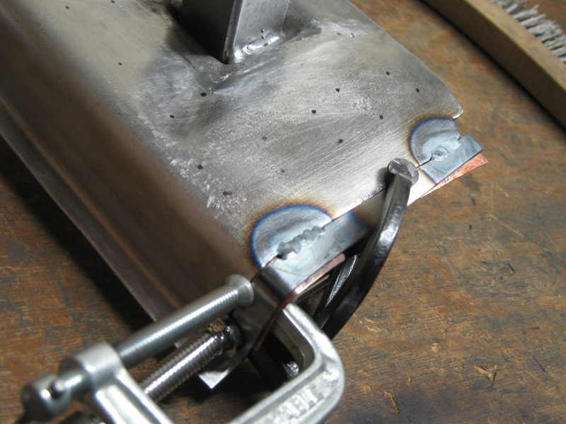
|
|
|
|
| nathansnathan |
Jun 22 2012, 11:36 PM
Post
#115
|
|
Senior Member Group: Members Posts: 1,052 Joined: 31-May 10 From: Laguna Beach, CA Member No.: 11,782 Region Association: None |
oops , I didn't mean to add so soon. got some error message? Anyway...
 Had to wire wheel the whole thing to get the galvanization off, drilling the holes for where it'll need to be welded. Wasn't happy with how short the flange to weld it on ws, maybe .030" inch shorter than stock in such a critical area. 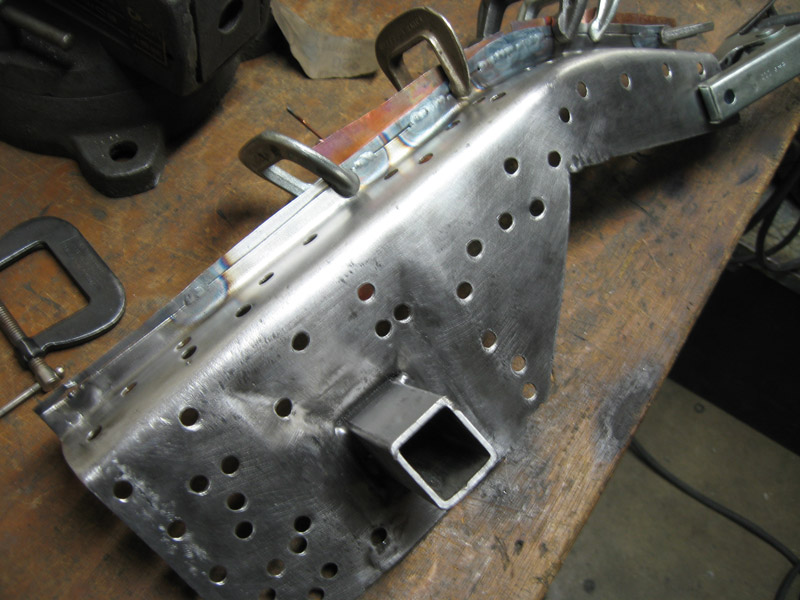 I etched everything and weld-primered the parts that would become inaccessible. The car part and the piece inside, too  rocker nut welded in 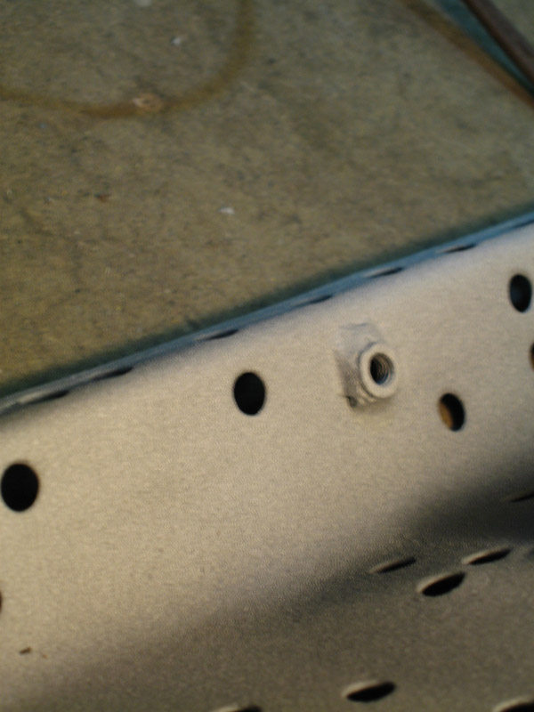 put it together, not quite done 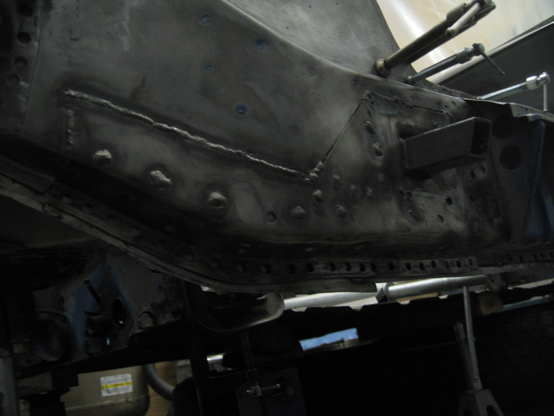 It all lines up though 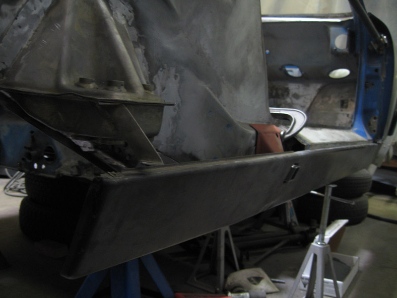 At that point I moved on to a bit of my own rd oversight where I;d made the bottom of the inner long about a 1'2 inch too short kind of. I'll post pics soon of that and the fix... and the fitting, not attached quite yet. (IMG:style_emoticons/default/smile.gif) (IMG:style_emoticons/default/smoke.gif) Attached image(s) 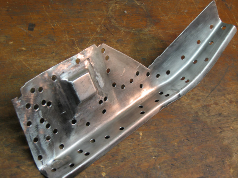
|
|
|
|
| nathansnathan |
Jun 23 2012, 12:00 AM
Post
#116
|
|
Senior Member Group: Members Posts: 1,052 Joined: 31-May 10 From: Laguna Beach, CA Member No.: 11,782 Region Association: None |
When I'd put the bottom of the long together, I had not taken the engine mount off the donor car and kind of put it, where it wanted to be.
All seems well 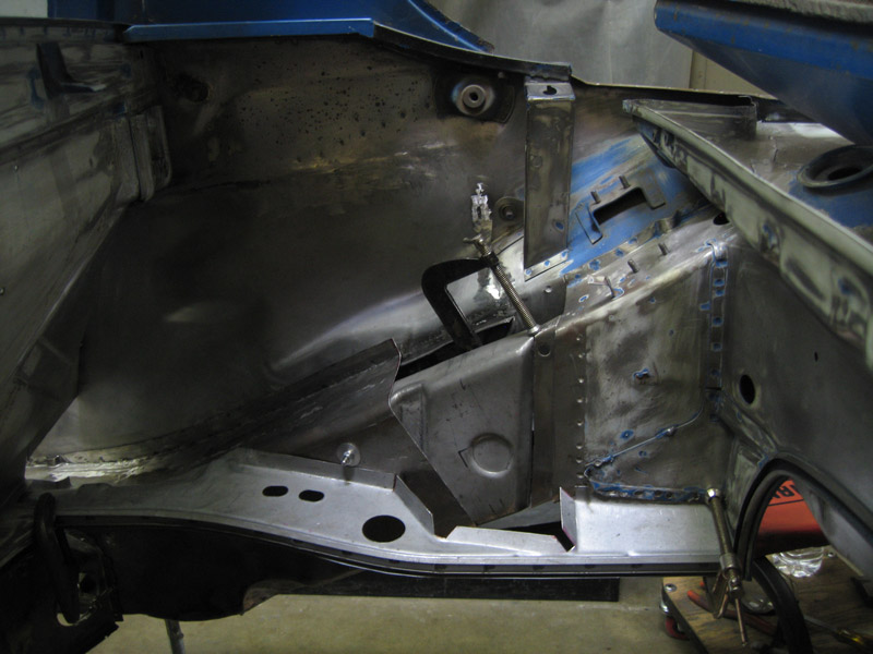 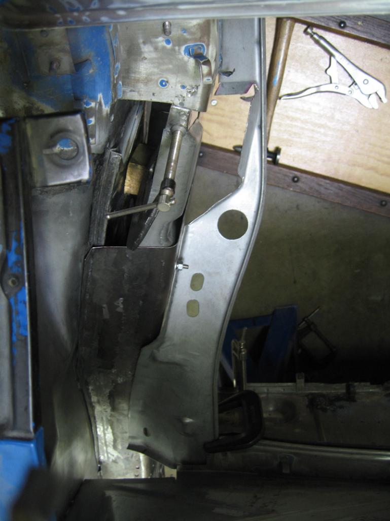 But try as I might with the bottom, it wasn't lining up right (IMG:style_emoticons/default/unsure.gif) 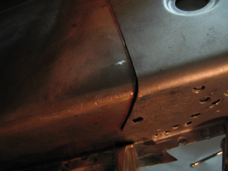 measured the donor car then to find I was off As it went Up the long it became almost 1/4 inch off. (IMG:style_emoticons/default/chair.gif) so.. 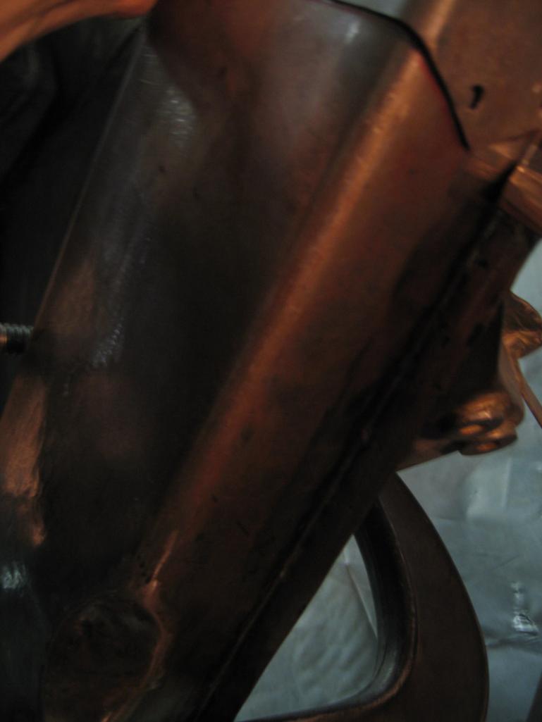 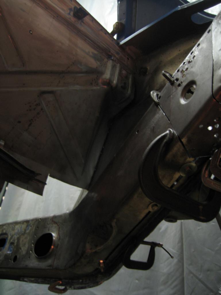 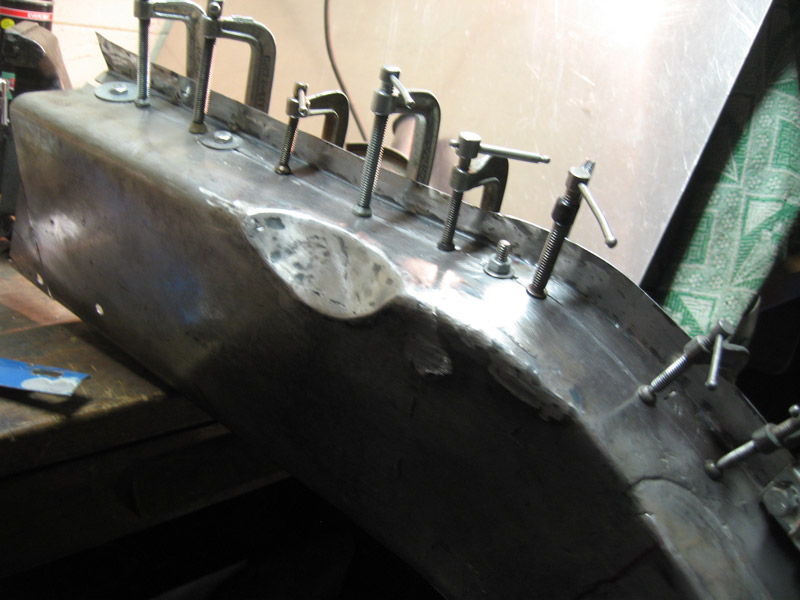 got it welded together, and smoothed even, there, I got copper flashing backing it. no pic currently of the fit from below, I will have to update later. moving on to the engine mount... (IMG:style_emoticons/default/type.gif) |
|
|
|
| nathansnathan |
Jun 23 2012, 12:22 AM
Post
#117
|
|
Senior Member Group: Members Posts: 1,052 Joined: 31-May 10 From: Laguna Beach, CA Member No.: 11,782 Region Association: None |
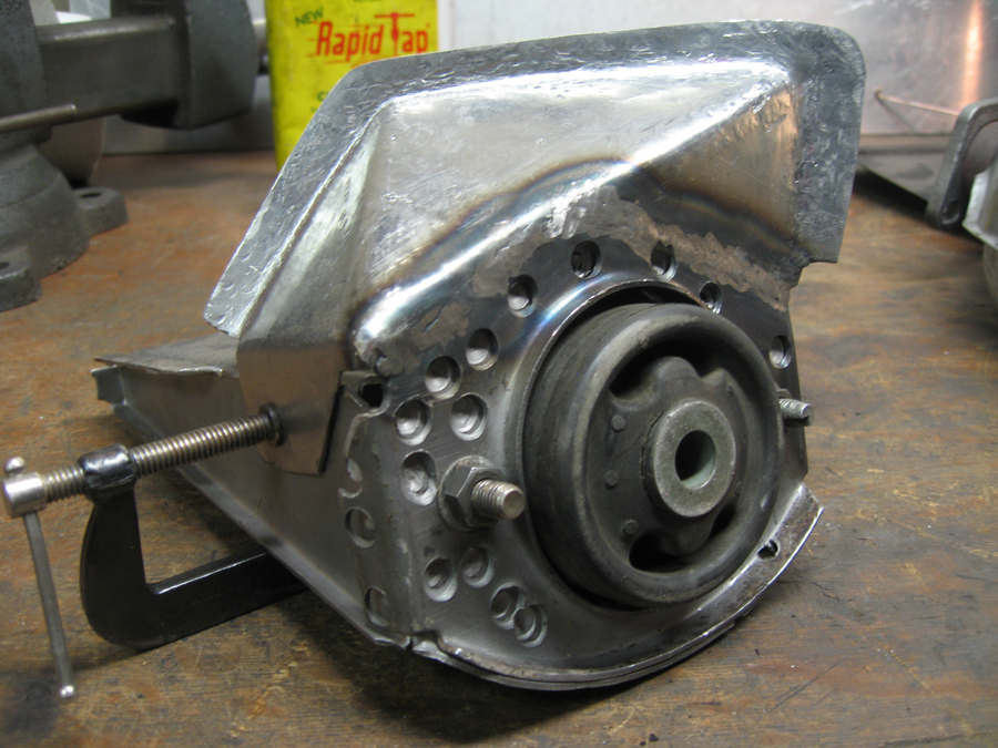
I'd been worried about the engine mount.
The good bottom bit on the left id from the driver's side of the donor car.The original driver side engine mount on the right, and below that the new piece I formed of 16 gauge cold rolled sheet in progress. 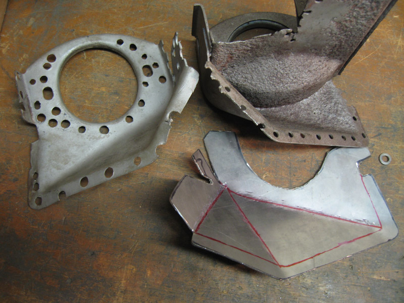 The bottom formed bit is the same side-to-side, but the top is symmetrically inverse 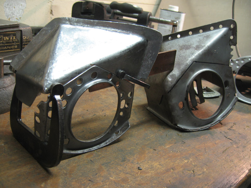 just got to ad the flange on the bottom of the one side, took it off the other 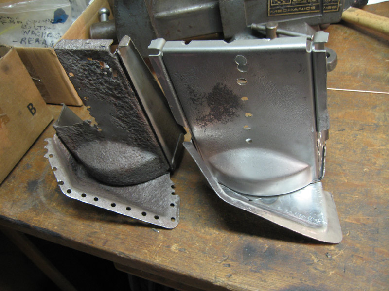 and fit up in the nook and jacked snug at the bottom (IMG:style_emoticons/default/grouphug.gif) 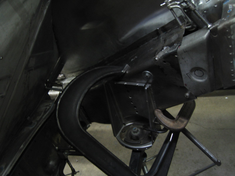 Working on putting the firewall back together this weekend, 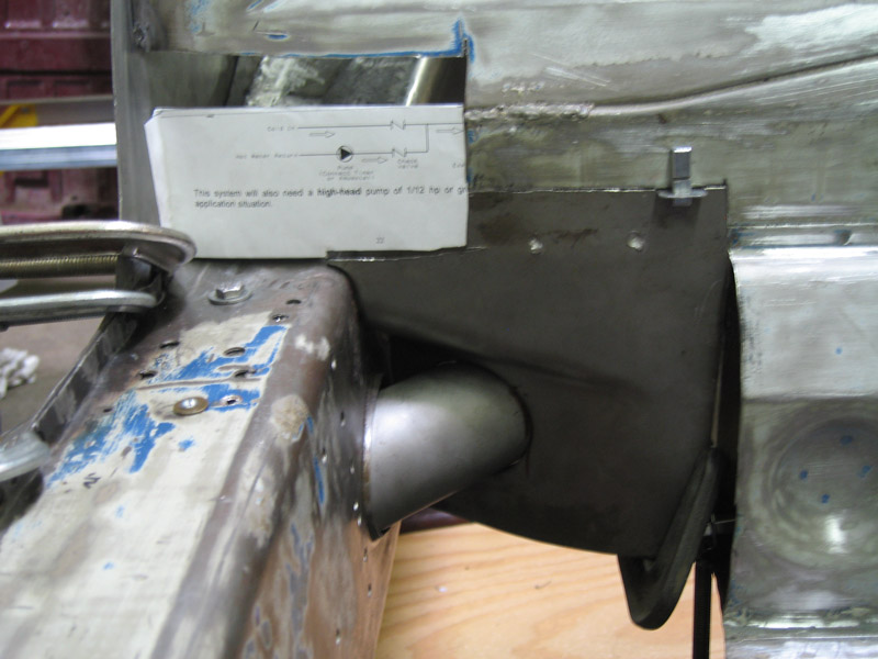 I need to bolt the firewall, tube, and long together and see if I can get it in so I can assemble it (weld) and then put it in, easier than building it on the car as you can't reach inside that way. soon fairly soon... Attached thumbnail(s) 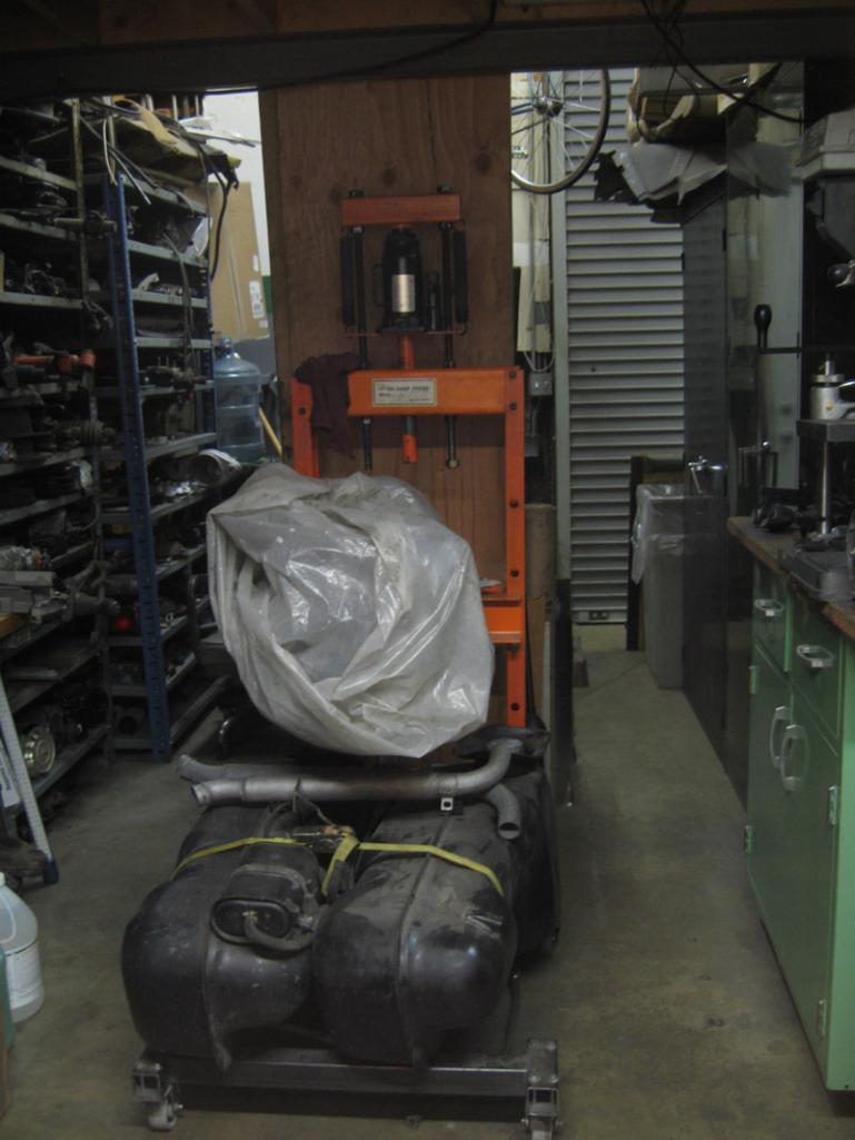
|
|
|
|
| saigon71 |
Jun 23 2012, 08:31 AM
Post
#118
|
|
Advanced Member Group: Members Posts: 2,006 Joined: 1-June 09 From: Dillsburg, PA Member No.: 10,428 Region Association: MidAtlantic Region |
Very impressive work man...keep it rolling! (IMG:style_emoticons/default/beerchug.gif)
|
|
|
|
| obscurity |
Jul 8 2012, 07:07 AM
Post
#119
|
|
Member Group: Members Posts: 411 Joined: 24-February 06 From: Atlanta ,GA Member No.: 5,628 Region Association: South East States |
This is some pretty amazing work. I have been struggling with what to do with my engine mount. This is inspirational!
John QUOTE(nathansnathan @ Jun 23 2012, 02:22 AM) I'd been worried about the engine mount. The good bottom bit on the left id from the driver's side of the donor car.The original driver side engine mount on the right, and below that the new piece I formed of 16 gauge cold rolled sheet in progress. The bottom formed bit is the same side-to-side, but the top is symmetrically inverse just got to ad the flange on the bottom of the one side, took it off the other and fit up in the nook and jacked snug at the bottom (IMG:style_emoticons/default/grouphug.gif) Working on putting the firewall back together this weekend, I need to bolt the firewall, tube, and long together and see if I can get it in so I can assemble it (weld) and then put it in, easier than building it on the car as you can't reach inside that way. soon fairly soon... |
|
|
|
| nathansnathan |
Jul 8 2012, 09:26 AM
Post
#120
|
|
Senior Member Group: Members Posts: 1,052 Joined: 31-May 10 From: Laguna Beach, CA Member No.: 11,782 Region Association: None |
Thanks, man. It's really good to hear the encouragement. I've been recapping all that is left to do and I'm thinking, I need to get better at this. (IMG:style_emoticons/default/biggrin.gif)
Was checking out your thread. Very ambitious, what you have done, and looking good. ... makes me think I've got it easy. You're making me look bad. (IMG:style_emoticons/default/chair.gif) (IMG:style_emoticons/default/biggrin.gif) (IMG:style_emoticons/default/biggrin.gif) |
|
|
|
| nathansnathan |
Jul 8 2012, 09:41 AM
Post
#121
|
|
Senior Member Group: Members Posts: 1,052 Joined: 31-May 10 From: Laguna Beach, CA Member No.: 11,782 Region Association: None |
A shot of it further along, still need to smooth it out with flap disk or now using roton pads on my die grinder, and to tap that bit in there.
 I'm pretty happy with it so far, got to put the filter holder on it still, and take it off the other, actually (IMG:style_emoticons/default/smash.gif) 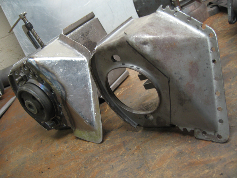 I've been smoothing/ prepping my long, both pieces, the inner removed the galvanneal mostly, to put them together. I've been distracted by some other projects, someone hit my bus in the parking ramp at work and I spent a week straightening and painting that. This weekend I am putting egt probes in the heat exchangers. I managed to move the car onto the dolly, though, and I'm loving being able to clean beneath it, ...and walk through the shop. (IMG:style_emoticons/default/blink.gif) 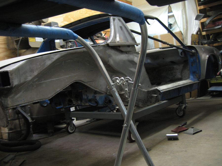 I was actually comparing the frequency of the rd jackplate piece there with an original that I found, using a guitar tuner. (IMG:style_emoticons/default/lol-2.gif) Very productive, I know, but they are somehow different, like in there temper or something because they weigh about the same, but they are just different.. (IMG:style_emoticons/default/smoke.gif) Thanks for the comments, again. I hope to post meaningful updates soon. (IMG:style_emoticons/default/smile.gif) |
|
|
|
| dheming |
Aug 8 2012, 01:29 PM
Post
#122
|
|
Newbie Group: Members Posts: 8 Joined: 9-January 11 From: Bay Area, CA Member No.: 12,574 Region Association: None |
Looking good. You should make your custom title "The Surgeon" (IMG:style_emoticons/default/beerchug.gif)
Are still using the same spot weld drill bit? Was just wondering how long they last. |
|
|
|
| nathansnathan |
Aug 8 2012, 02:24 PM
Post
#123
|
|
Senior Member Group: Members Posts: 1,052 Joined: 31-May 10 From: Laguna Beach, CA Member No.: 11,782 Region Association: None |
QUOTE(dheming @ Aug 8 2012, 12:29 PM) Looking good. You should make your custom title "The Surgeon" (IMG:style_emoticons/default/beerchug.gif) Are still using the same spot weld drill bit? Was just wondering how long they last. Thanks. (IMG:style_emoticons/default/beer.gif) I started out just using a regular drill bit, but it does make extra work. There are few options for spot weld drills, even just at Eastwood, but I went with the expensive ones. I got replacement guide bits and cutting tips, but I'm still using the same one after a ridiculous amount of welds drilled. I use cutting oil fanatically. The drawback to spot weld drills is they are all huge, the hole they make. http://www.eastwood.com/ew-skip-proof-spotweld-cutter.html# (IMG:http://www.914world.com/bbs2/uploads_offsite/www.eastwood.com-11782-1344457453.1.jpg) (IMG:http://www.914world.com/bbs2/uploads_offsite/www.eastwood.com-11782-1344457455.2.jpg) I'm currently full on building the rotisserie. I've ordered the electric cable hoists, like we talked about. I want to be able to use it on the bus someday so it's going to be pretty insane; I got the 750/1500lbs ones. -Weird that they have gone up in price since last week? They were $182 and now they are $220. I will post the drawing when I get home; it's kind of a work in progress. (IMG:http://www.914world.com/bbs2/uploads_offsite/www.northerntool.com-11782-1344457455.3.jpg) (IMG:http://www.914world.com/bbs2/uploads_offsite/www.northerntool.com-11782-1344457455.4.jpg) |
|
|
|
| nathansnathan |
Aug 8 2012, 06:48 PM
Post
#124
|
|
Senior Member Group: Members Posts: 1,052 Joined: 31-May 10 From: Laguna Beach, CA Member No.: 11,782 Region Association: None |
I've been turning over (IMG:style_emoticons/default/lol-2.gif) ideas of how to do this for months now. The challenge is to be able to lift it high enough to fully flip it, from the position it would be in sitting on its tires.
I want to be able to lift my bus on this also, just the body of course, but I've made it beefy to handle that. Another part of the challenge is that you need to lift both sides at once, because if you don't, the car becomes like the the hypotenuse of a triangle, sort of, wanting to stretch. The problem is that variation in the axis from end to end would also put stress on the car, in a rigid setup. And on top of this, the hoists move 3.5 inches a second direct, half that reduced with the pulley setup, but it seems inevitable that something should get off, one side higher. I can imagine tearing the car up with some stuck cable scenario, and so I've designed it to flex in the final version. The long arm ram jacks have 19 inches of travel, and you need at least 25 so this one wasn't working. 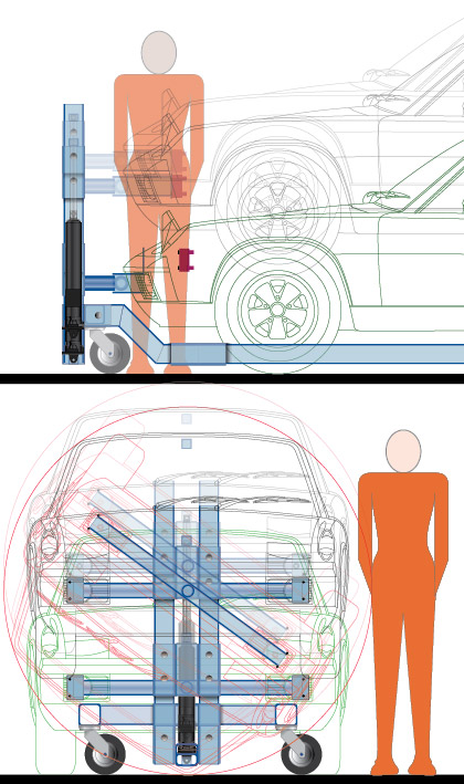 I went through more ideas in between, toying with 'samba rotisseries' which are like a pair of octagons, partial versions of that as well. But I ended up with this, trying to keep it simple (IMG:style_emoticons/default/av-943.gif) There is to be a sleeve of plate (by my ankle there, should be in the side view but was left below), similar to that which goes up and down along the vertical support, but on the crossbeam so it can elongate - got to figure out how to limit it. There are hinges which are integrated to the mounts, and then a hinge between the pivot and the support arm. The whole car is like part of a joint. (IMG:style_emoticons/default/smoke.gif) and can pivot either way at both ends, if not for the other. 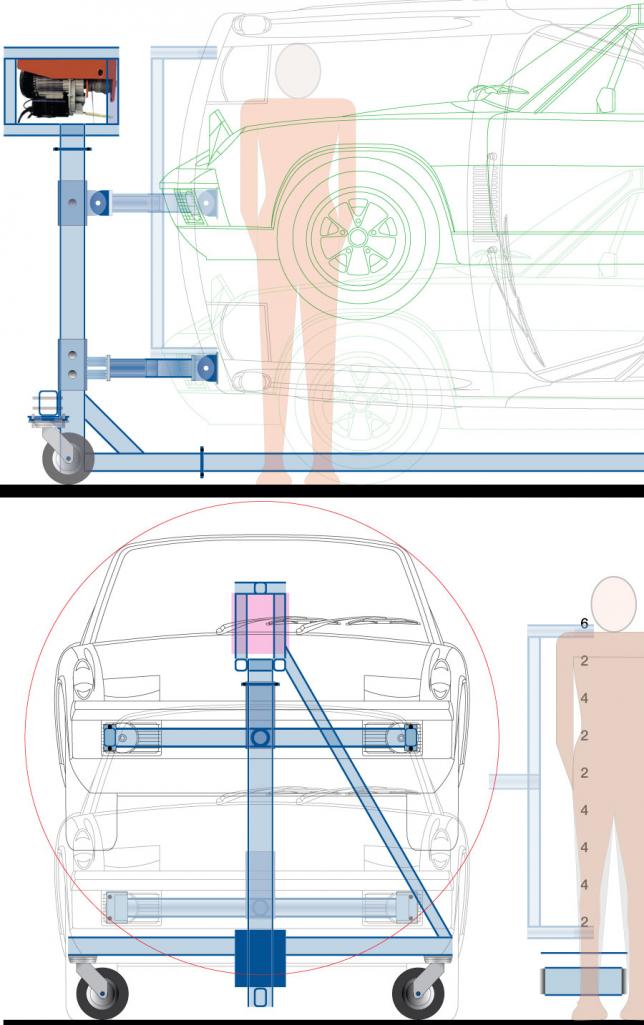 |
|
|
|
| dheming |
Aug 9 2012, 03:56 PM
Post
#125
|
|
Newbie Group: Members Posts: 8 Joined: 9-January 11 From: Bay Area, CA Member No.: 12,574 Region Association: None |
Nice to know that the spot weld cutters last so long. Really $35 is not that bad for such a thing. If I decide to remove my pedal box I will be getting one for sure.
Glad to see you moving forward on the rotisserie. The nice thing about going with hoists is that you can also use them in an A-frame to make a small shop crane. Multifunctionality is always a good thing when buying tools. Making the car able to flex/hinge with four joints might not be the greatest idea. The thing is that having the hinges the way you show in the drawing, as soon as you put weight on it you will effectively pull the two end towers towards each other as the load moves downwards a bit. Just visualize a rope connecting the two towers, now pull down hard on the middle of the rope. This will get worse the higher up the tower the load moves due to leverage. Also I foresee that when you rotate the car 90° to vertical that it will want to oscillate side to side a bit when you go to work on it, again due to the towers bending inwards a bit. Now if you only had two hinge joints you would still allow for unequal hoist speeds, but you wouldn't have the drooping or swaying issues. So I'd keep the hinges that are on the mounts and get rid of the ones on the vertical towers. Also what are you planning to do for safety stops, like if the cable breaks on the way up? As to the crossbeam elongation limiter, you could just drill a series of holes and then cut/grind the excess out to make a slot on the inner tube. Then you could just screw a bolt through the outer tube into that slot to have a limited range of sliding allowed. I imagine a slot a few inches long would be fine. |
|
|
|
| nathansnathan |
Aug 9 2012, 04:38 PM
Post
#126
|
|
Senior Member Group: Members Posts: 1,052 Joined: 31-May 10 From: Laguna Beach, CA Member No.: 11,782 Region Association: None |
QUOTE(dheming @ Aug 9 2012, 02:56 PM) Nice to know that the spot weld cutters last so long. Really $35 is not that bad for such a thing. If I decide to remove my pedal box I will be getting one for sure. Glad to see you moving forward on the rotisserie. The nice thing about going with hoists is that you can also use them in an A-frame to make a small shop crane. Multifunctionality is always a good thing when buying tools. Making the car able to flex/hinge with four joints might not be the greatest idea. The thing is that having the hinges the way you show in the drawing, as soon as you put weight on it you will effectively pull the two end towers towards each other as the load moves downwards a bit. Just visualize a rope connecting the two towers, now pull down hard on the middle of the rope. This will get worse the higher up the tower the load moves due to leverage. Also I foresee that when you rotate the car 90° to vertical that it will want to oscillate side to side a bit when you go to work on it, again due to the towers bending inwards a bit. Now if you only had two hinge joints you would still allow for unequal hoist speeds, but you wouldn't have the drooping or swaying issues. So I'd keep the hinges that are on the mounts and get rid of the ones on the vertical towers. Also what are you planning to do for safety stops, like if the cable breaks on the way up? As to the crossbeam elongation limiter, you could just drill a series of holes and then cut/grind the excess out to make a slot on the inner tube. Then you could just screw a bolt through the outer tube into that slot to have a limited range of sliding allowed. I imagine a slot a few inches long would be fine. About multi-functionality, I'm thinking of it with the 2 ends bolted together, fitting a sort of platform in between to make a super heavy duty stand/ lift , to like get an engine off a jack and onto an engine stand for example. About the stress relieving hinges, there are 4 at the mounts that would pivot if one end of the car only was to be raised while the car was in its upright position. But say you want to raise or lower 1 end when it's flipped on its side, 90 degrees. For this there are the 2 pivots at the middle where these meet the verticals - these pivot in a different axis than the other. The drawing shows the top (raised up) "yoke" in both positions at once so it looks kind of like they pivit in the same axis, but no. You do start to imagine regardless, the stress, say on the bumper mounts, the tops wanting to go inward, the bottoms out, but it's necessary imo to relieve the stress of it cocking. If the car were flipped like 70 degrees, you might see some combination of the slop in both joints combined. It does stress the horizontal, and the joints between, but the verticals and the horizontals, as well as the diagonals are all 1/4 inch wall, 2x3 for the horizontals and diagonals, 4x4 for the verticals. The cross pieces to which the casters are connected, I realized after I bought them, 3/16 wall, but the stress on those should be pretty controlled. Safety measures while lifting it? Just go up one 'hole' at a time so if it does break, the cable, it won't fall too far. Going with the bigger hoists I consider something of a preventative measure, the 200/400 has 1/8" cable, the 500/1000 has 5/32. The ones I got, 750/1500 must have a typo on the site to say 9/50 inch? I'm thinking the slot will probably be the way for the middle section, like you've said. |
|
|
|
| dheming |
Aug 9 2012, 06:09 PM
Post
#127
|
|
Newbie Group: Members Posts: 8 Joined: 9-January 11 From: Bay Area, CA Member No.: 12,574 Region Association: None |
Ah yeah, I see what you are saying about the hinges. Should be fine. (IMG:style_emoticons/default/smile.gif)
If you scale up from the numbers you gave for the other cables, the 750 should have around a 0.191" to 0.242" cable. So maybe they meant 9/32" which would be around 0.281". Not sure, you will have to measure when you get them. |
|
|
|
| dheming |
Sep 12 2012, 07:16 PM
Post
#128
|
|
Newbie Group: Members Posts: 8 Joined: 9-January 11 From: Bay Area, CA Member No.: 12,574 Region Association: None |
Any progress on the rotisserie after getting the hoists?
|
|
|
|
|
1 User(s) are reading this topic (1 Guests and 0 Anonymous Users)
0 Members:

|
Lo-Fi Version | Time is now: 6th October 2024 - 03:12 AM |
Invision Power Board
v9.1.4 © 2024 IPS, Inc.