|
|

|
Porsche, and the Porsche crest are registered trademarks of Dr. Ing. h.c. F. Porsche AG.
This site is not affiliated with Porsche in any way. Its only purpose is to provide an online forum for car enthusiasts. All other trademarks are property of their respective owners. |
|
|
  |
| nathansnathan |
 Jun 11 2013, 10:19 PM Jun 11 2013, 10:19 PM
Post
#141
|
|
Senior Member    Group: Members Posts: 1,052 Joined: 31-May 10 From: Laguna Beach, CA Member No.: 11,782 Region Association: None |
3 months and no updates? Man, I did not even see this. I wasn't subscribed anymore. (IMG:style_emoticons/default/biggrin.gif) |
| nathansnathan |
 Jun 11 2013, 10:38 PM Jun 11 2013, 10:38 PM
Post
#142
|
|
Senior Member    Group: Members Posts: 1,052 Joined: 31-May 10 From: Laguna Beach, CA Member No.: 11,782 Region Association: None |
Well, I decided to take on a 'little thing' in the meantime, the driver fresh air inlet.
I got the seam sealer out. 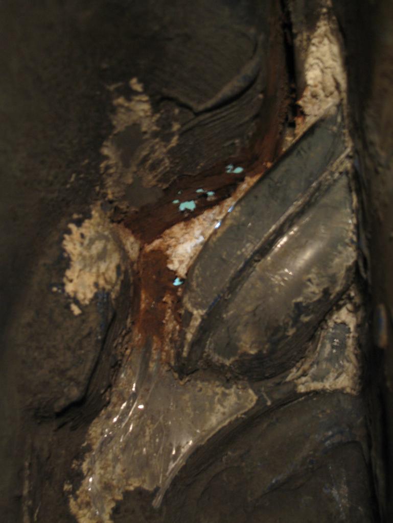 I had wondered how bad it was really. 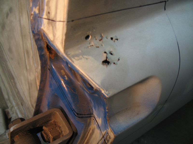 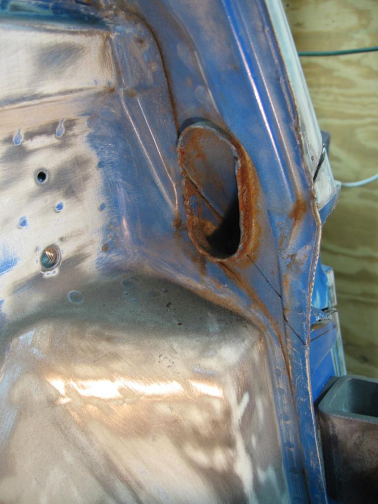 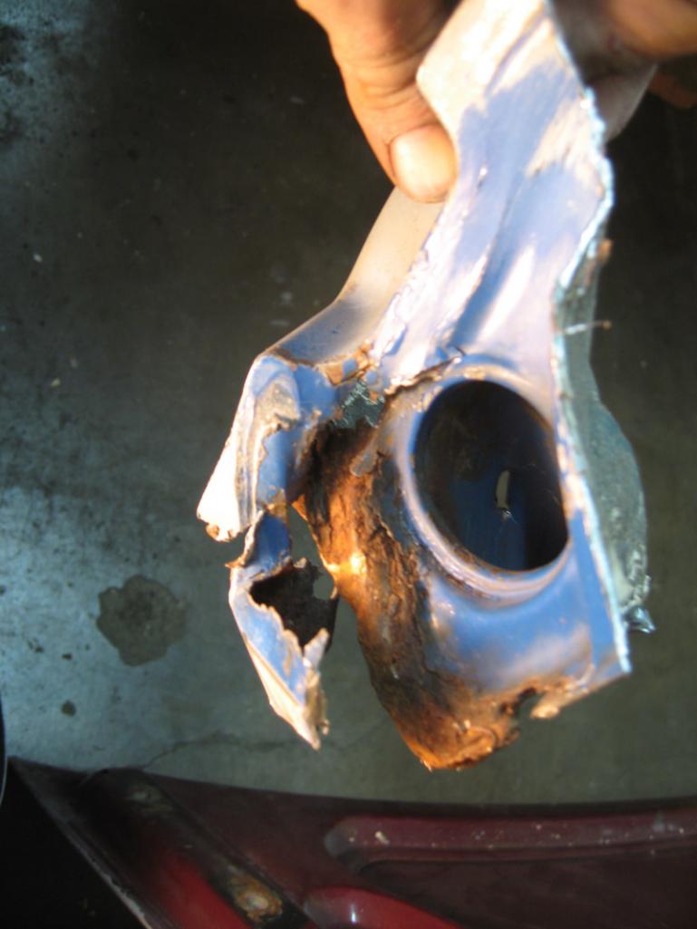 The new piece to go in 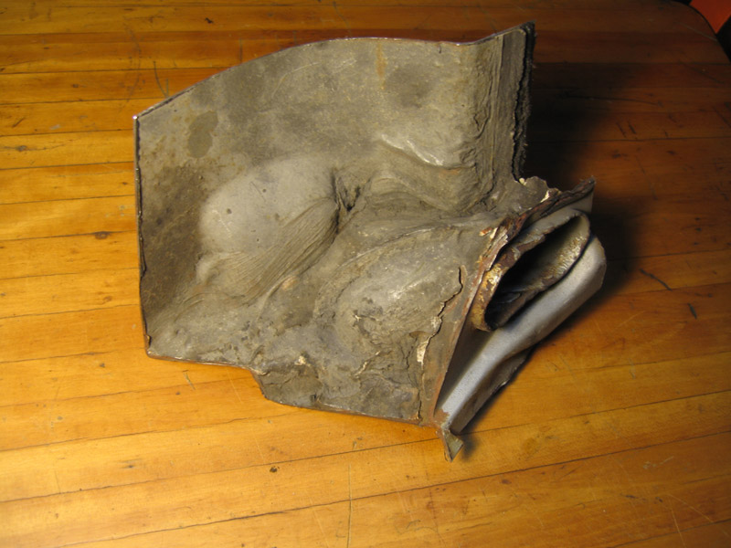 I had damaged it cutting it out, but easy to fix. Cleaned. 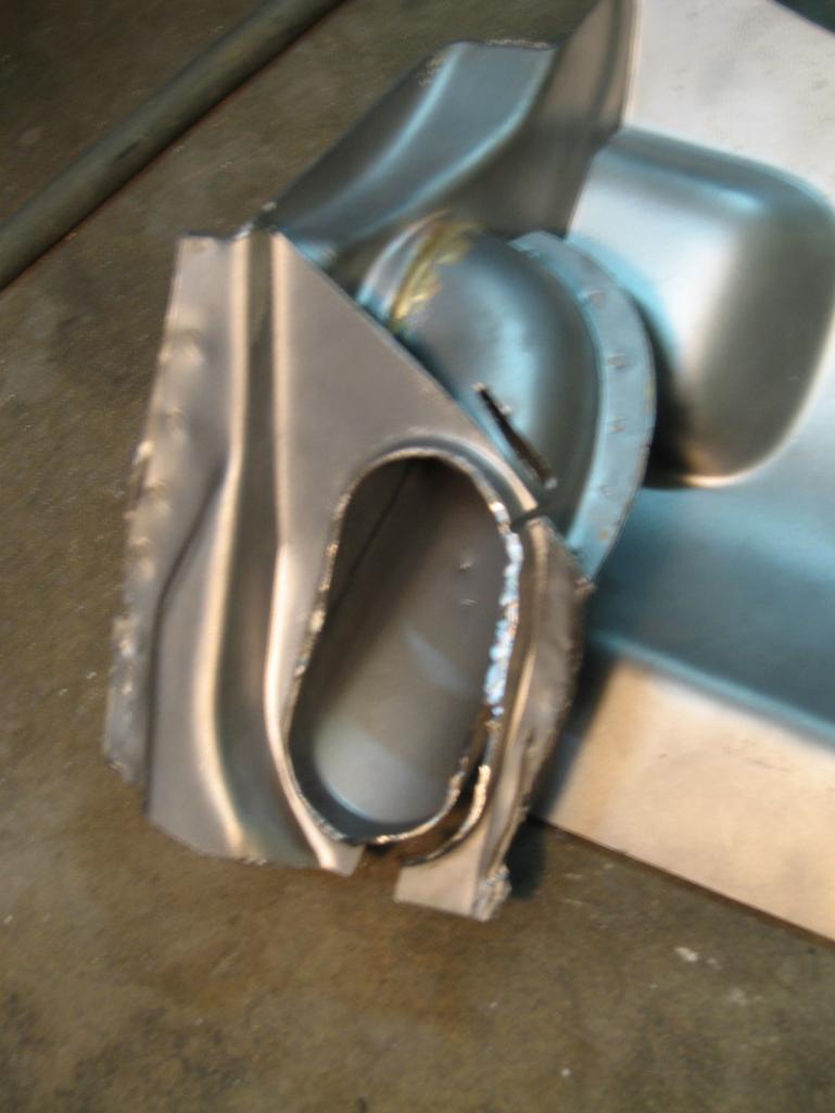 It is hard to get the ready-to-go-in shot because the shiny metal reflects and autofocus won't work. New piece in 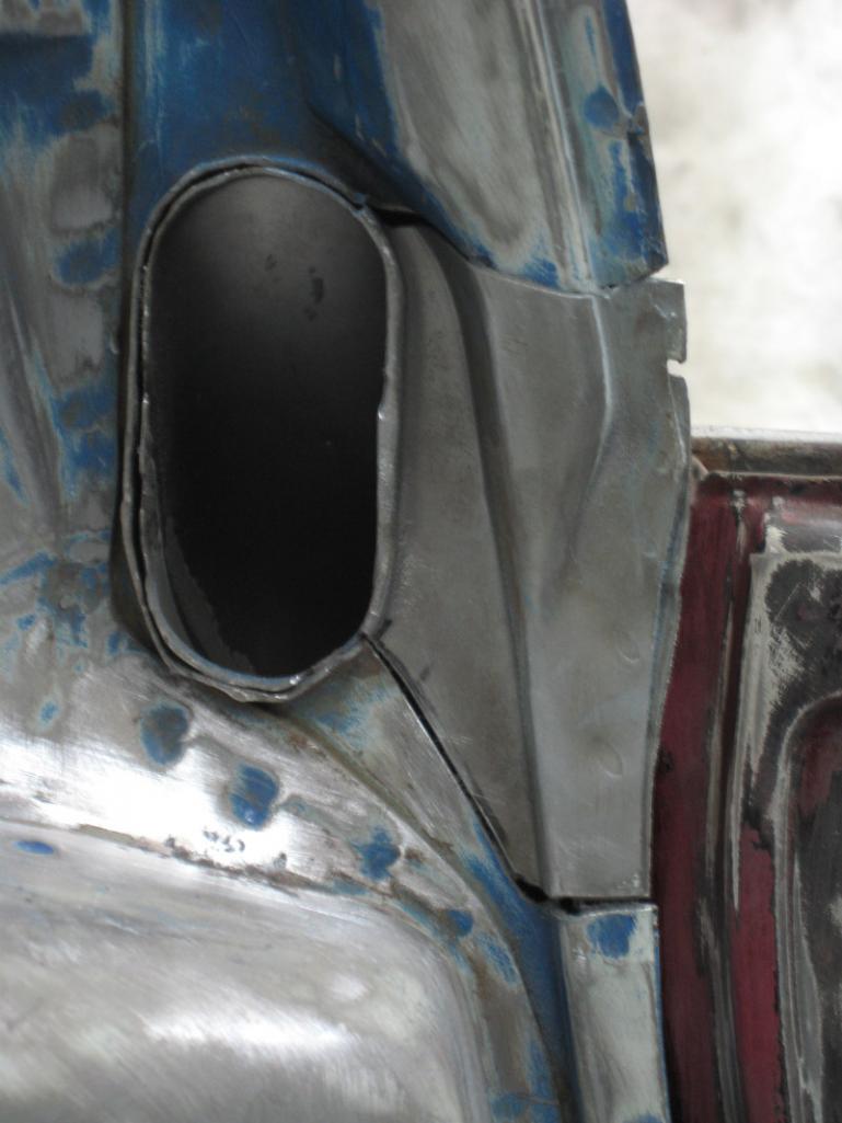 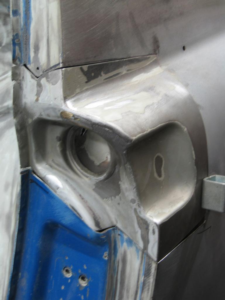 I have the car back on jack stands (off the dolly). But, besides the 2 flat-tops, they are all leveling jack stands. I've got the car leveled using a machinists level, supported by 4 pairs. (IMG:style_emoticons/default/rolleyes.gif) - thats 2 at the firewall, 2 by the front firewall, 2 at the front and 2 at the rear trunk area. There are also some random additional stands positioning the firewall and floor for fitting purposes. I have the driver side braces removed from the door to make sure gap is right and for fitting the air inlet piece. 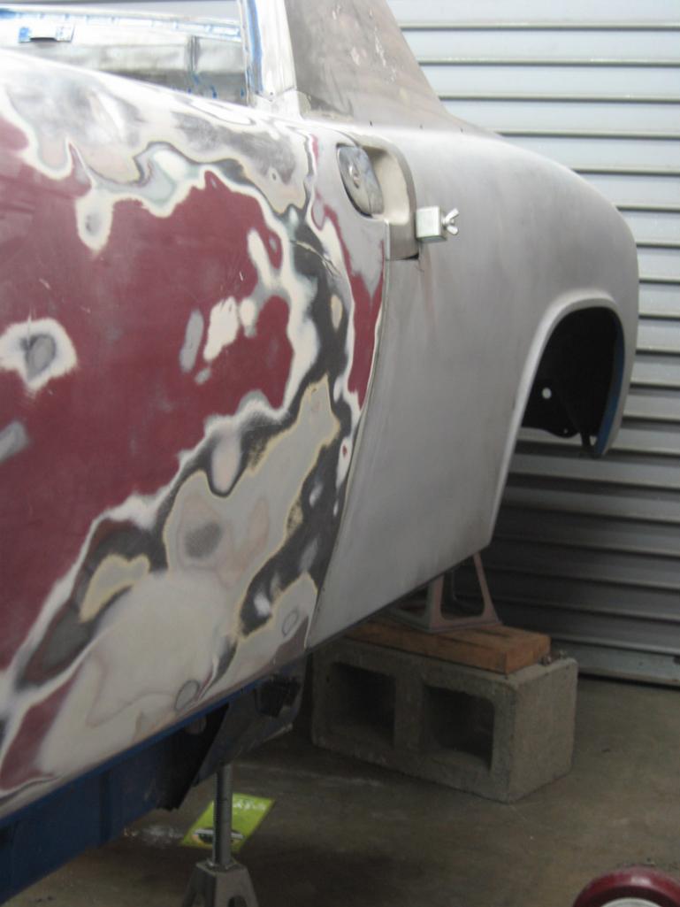 So far it is just fit up, not welded in....still wondering about this pitting.... I may get the spot blaster going on it and see what is under the white stuff. 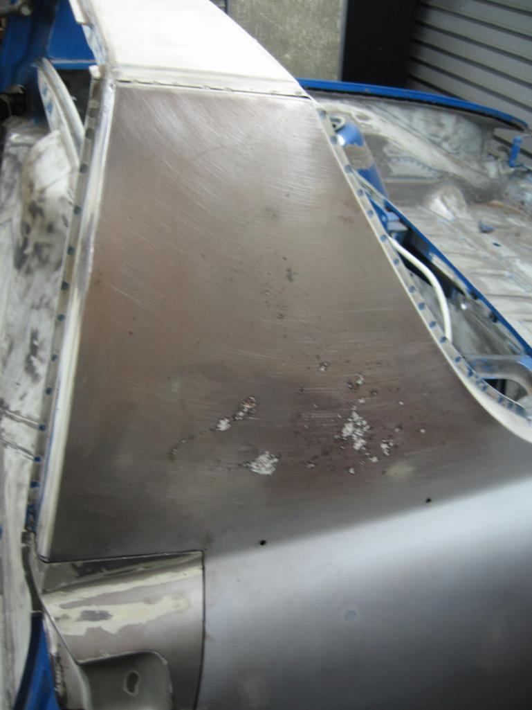 |
| nathansnathan |
 Jun 11 2013, 11:06 PM Jun 11 2013, 11:06 PM
Post
#143
|
|
Senior Member    Group: Members Posts: 1,052 Joined: 31-May 10 From: Laguna Beach, CA Member No.: 11,782 Region Association: None |
I have spent a lot of time on the rotisserie. This is my current drawing;
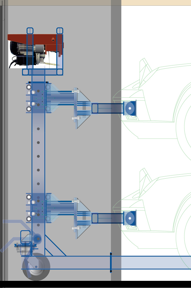 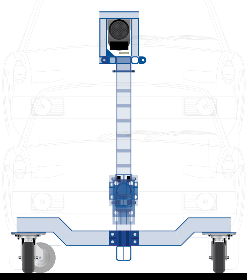 I have added adjustment for the center of gravity of the body. According to McMark, it is about an inch below the 'lip' in the front and rear. This is about 3 inches up from the line that goes through the center of the bumper mount holes. So the pivot is offset 3 inches from the beam and there is adjustability of 2 inches up and down for fine tuning. I am going up to visit Derek in Oakland, to make use of the mill at his work to form the slots. C-notched (IMG:style_emoticons/default/biggrin.gif) -root pass here 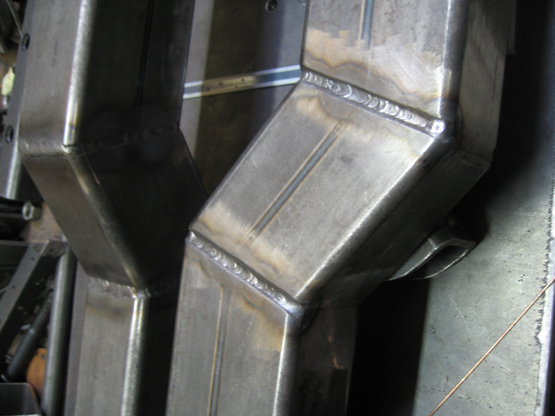 Through pipes welded in. I turned these on the lathe, .770+/-.005 inch ID 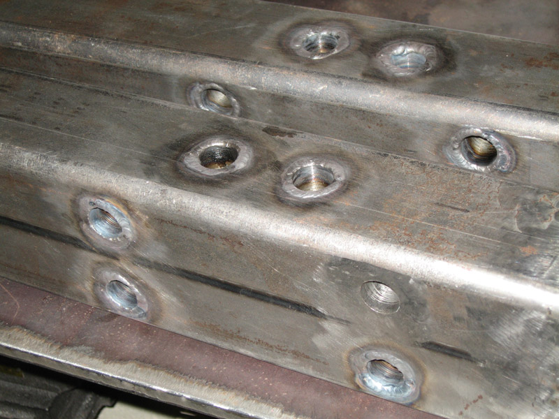 I am trying to finish the support beams smooth, with grinding wheel flush and flap disk smooth. Currently out of disks. 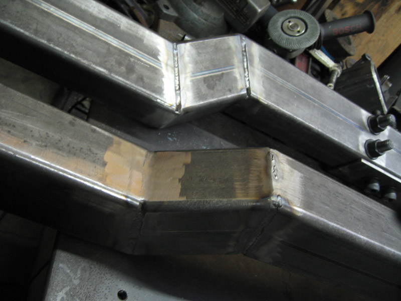 Caps fusion welded, and caster plates welded with just the root pass so far. 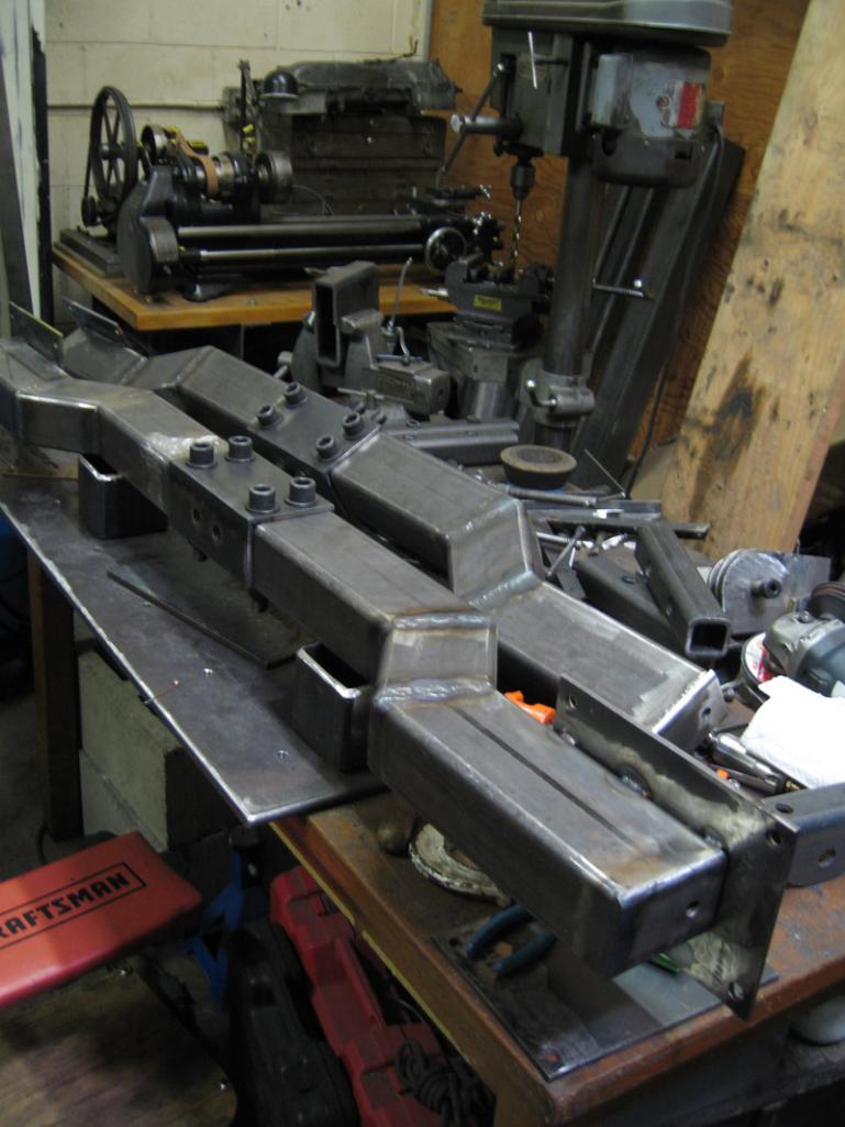 Working on the cable hoist mounts, my "cages". Mocked up and part tacked 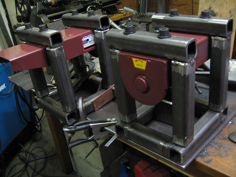 The cut material. Welding the through tubes there. Bevel-ground and mill scale sanded. (IMG:style_emoticons/default/welder.gif) 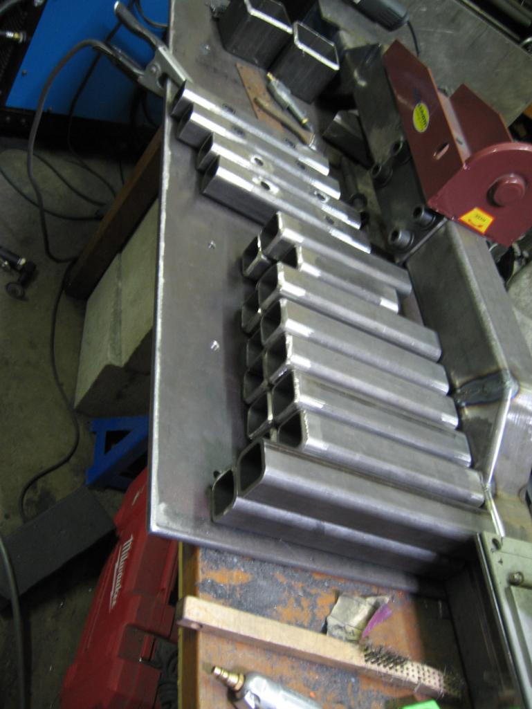 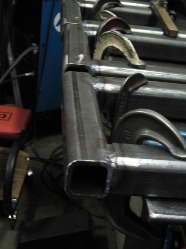 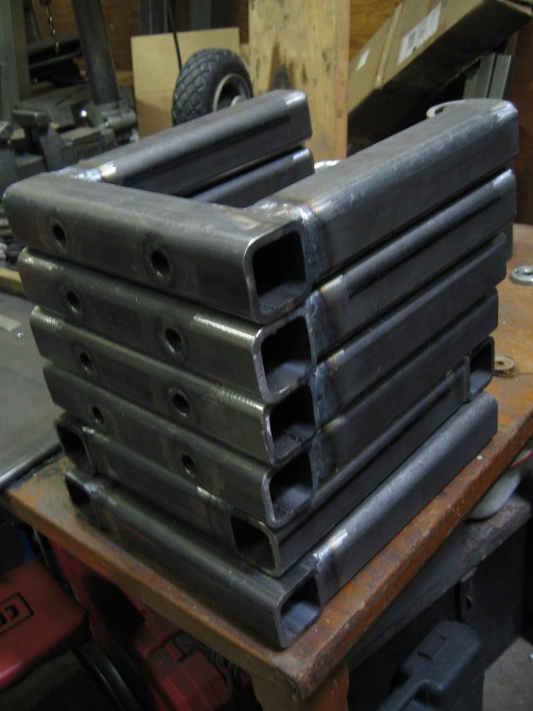 The stands tacked 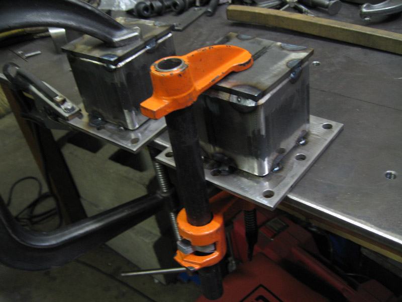 Enlarged the 7/16 nut-serts in the mounting plates 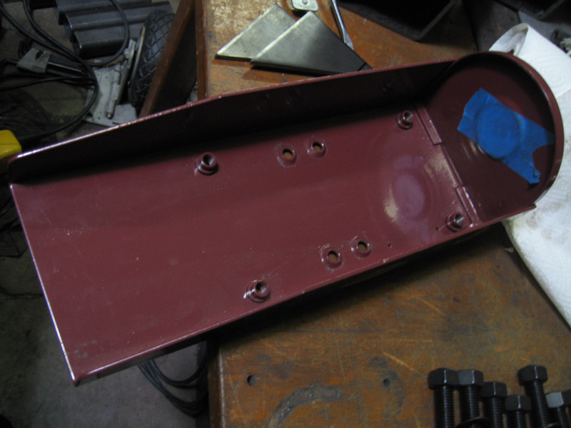 to 5/8 square weld nuts 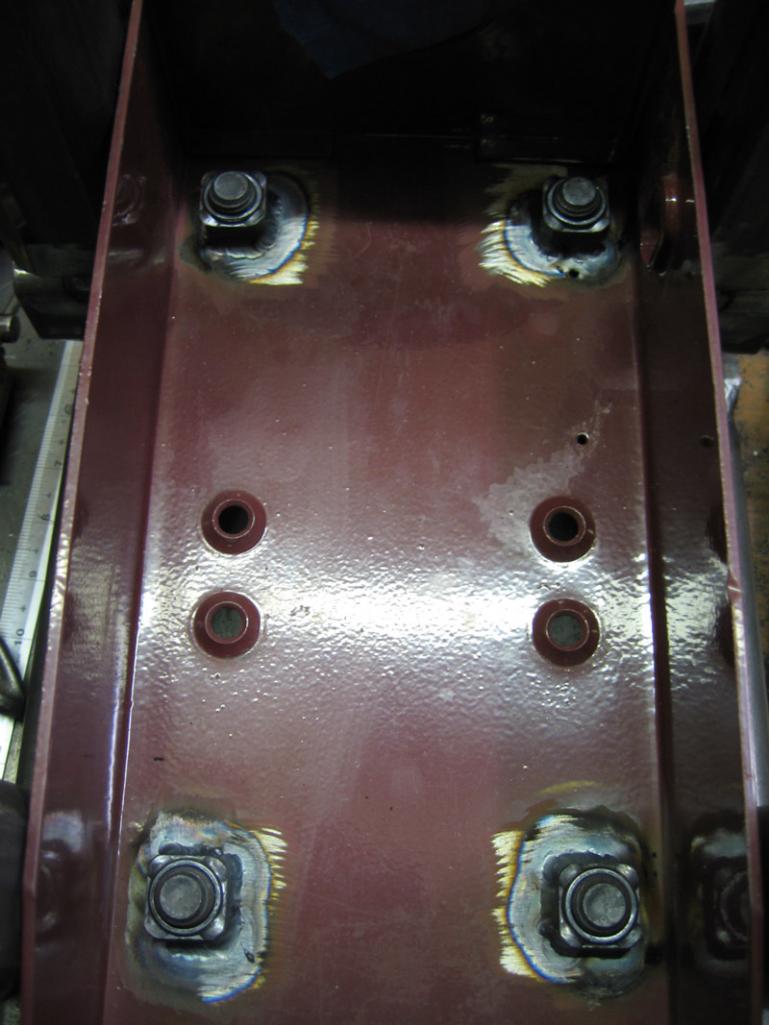 and now out of argon (IMG:style_emoticons/default/smoke.gif) I need to do the sliders to do the verticals (holes, tubes, diagonals, flanges). coming along, I guess. (IMG:style_emoticons/default/biggrin.gif) Attached image(s) 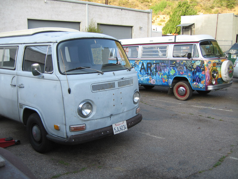
|
| nathansnathan |
 Jun 20 2013, 07:26 PM Jun 20 2013, 07:26 PM
Post
#144
|
|
Senior Member    Group: Members Posts: 1,052 Joined: 31-May 10 From: Laguna Beach, CA Member No.: 11,782 Region Association: None |
I had the tires unmounted from the wheels. They were all shot and mismatched, etc. I had 4 from the parts car. I kept the parts car's spare mounted, an unused 165 series Continental that is so vintage looking, I want to hang it on my wall.
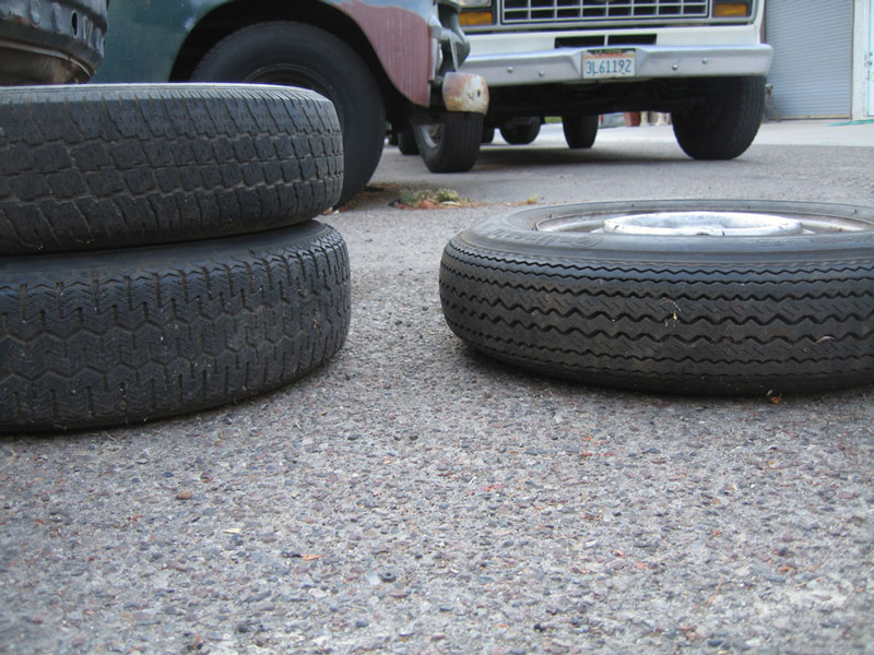 I sort of expected them all to be the same... (IMG:style_emoticons/default/unsure.gif) 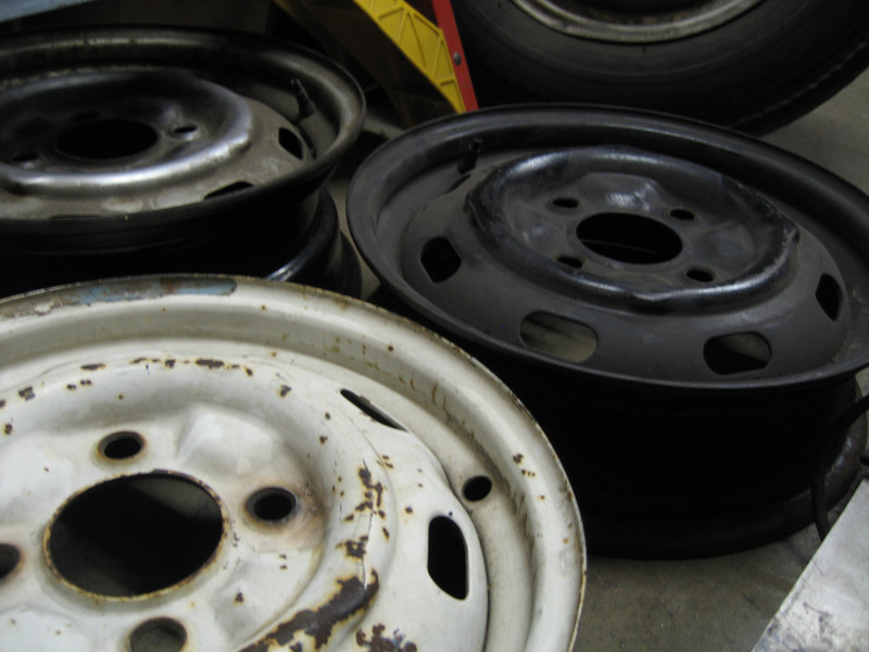 Lip to lip, they measure; the white one is 5 inches , the black is 5 1/2, and the silver is 6 3/4 inches lip to lip. I have a rust-colored (IMG:style_emoticons/default/rolleyes.gif) that matches the white as well. I'm not sure what the spare is. It's hard to tell with the tire on. It has a sizable dent in the lip even if it wasn't serving as such great art. So I know I had posted pics of the mahles before, and I always wanted a 914 with 'baby gasburners' (even though I used to think they were just gasburners- didn't know about 5 lug) but......I am really wanting to have silver steelies.... with 165's on them. I know that I will never have car of the month with 165's and no one will want to be my friend here. (IMG:style_emoticons/default/biggrin.gif) (IMG:style_emoticons/default/driving-girl.gif) Unfortunately I traded the wheels that were on the blue car to Dave to keep the parts car he had rolling, so I don't have the original wheels.... I will try to get in touch with him, beach914. The book says standard wheels are 4 1/2" and the optional steelie is 5 1/2. Where are they measuring that from? I am trying to figure out what I have here. Thinking I want the thinnest ones. Would an appearance group car automatically have had the 5 1/2's? I had thought those were pretty uncommon... but shows what I know with my 6 3/4's. (IMG:style_emoticons/default/biggrin.gif) (IMG:style_emoticons/default/huh.gif) |
| nathansnathan |
 Sep 10 2013, 10:43 PM Sep 10 2013, 10:43 PM
Post
#145
|
|
Senior Member    Group: Members Posts: 1,052 Joined: 31-May 10 From: Laguna Beach, CA Member No.: 11,782 Region Association: None |
It's been awhile since I've updated. My camera had got broken, but I have been at it. (IMG:style_emoticons/default/stirthepot.gif) (IMG:style_emoticons/default/welder.gif) (IMG:style_emoticons/default/smash.gif) (IMG:style_emoticons/default/smoke.gif) (IMG:style_emoticons/default/smash.gif) (IMG:style_emoticons/default/smoke.gif) (IMG:style_emoticons/default/smash.gif) (IMG:style_emoticons/default/smash.gif) (IMG:style_emoticons/default/welder.gif) (IMG:style_emoticons/default/stirthepot.gif) (IMG:style_emoticons/default/smash.gif) (IMG:style_emoticons/default/yellowsleep[1].gif)
Where the inner long meets the front wheel well is mig welded and it's easier to cut out than grind the welds in place. 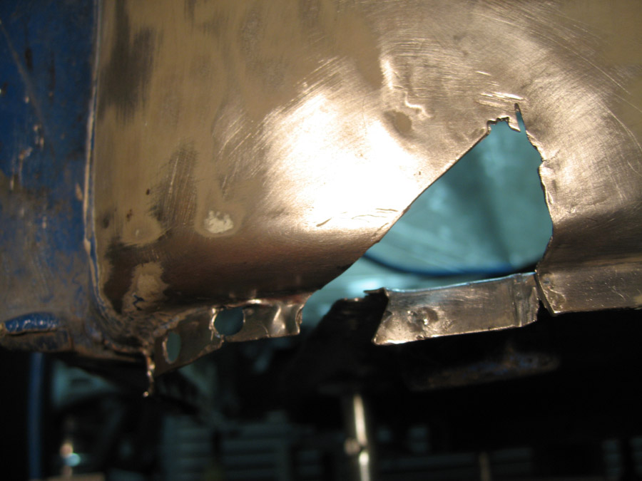 Inside 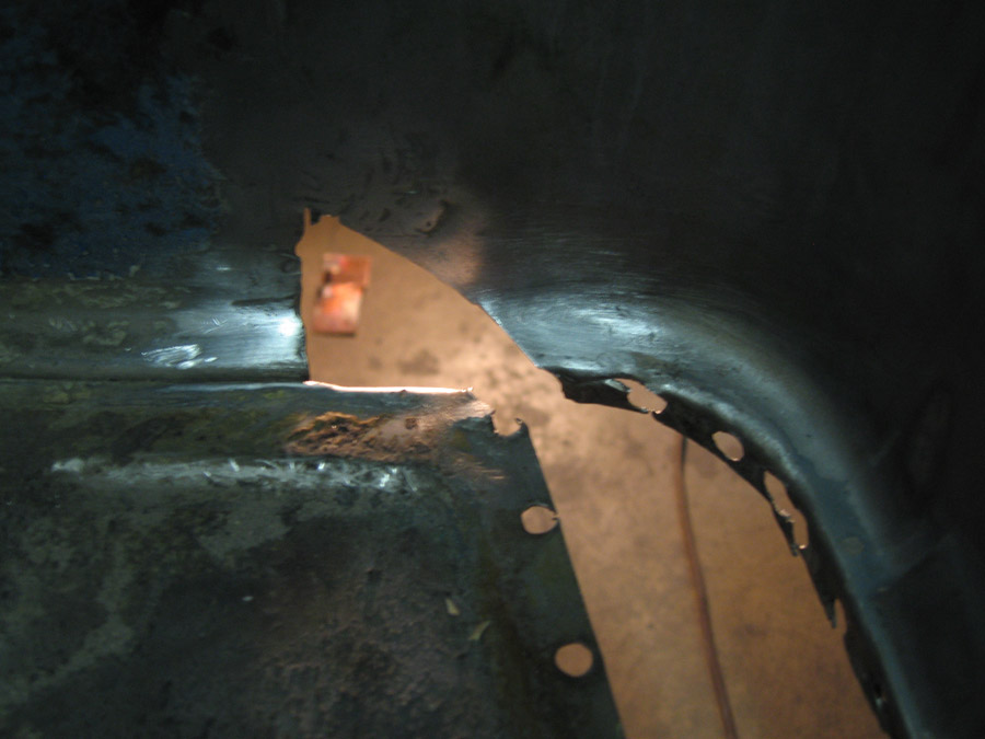 I filled and ground the holes left from drilling the spot welds, the original piece removed from the long. 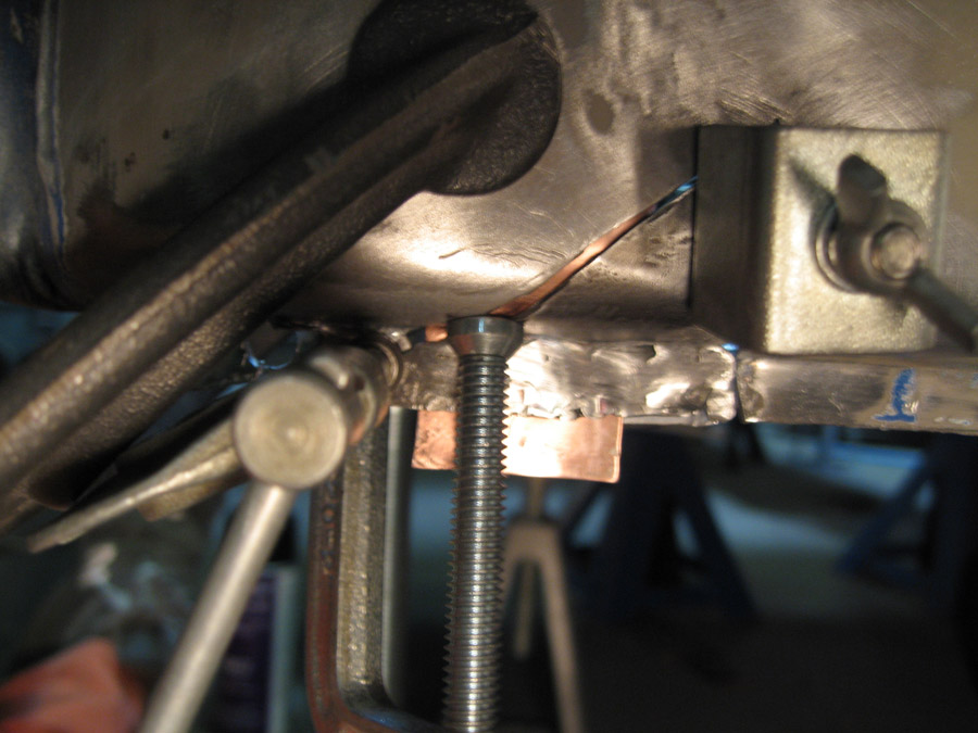 I have a thumb wheel for my tig torch. It is tricky to lie on your back. 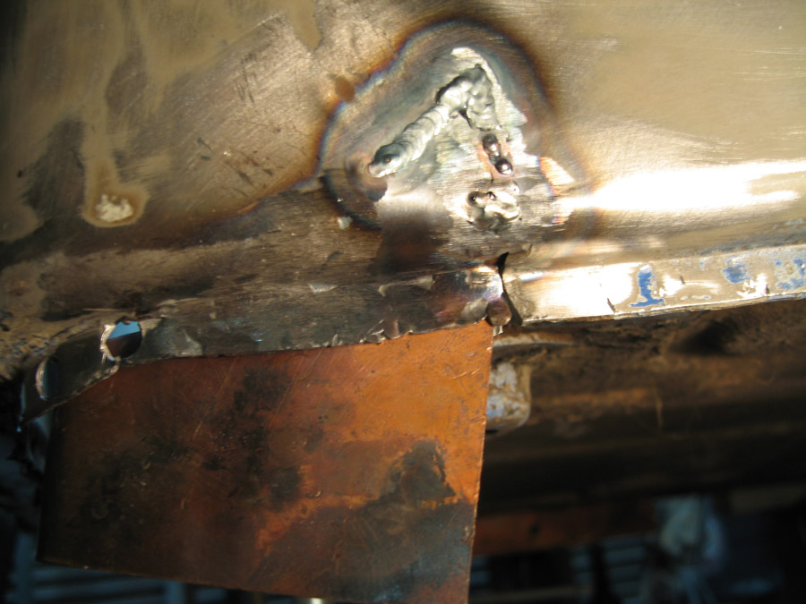 Grinding and sanding. I may fix the bottom better.... 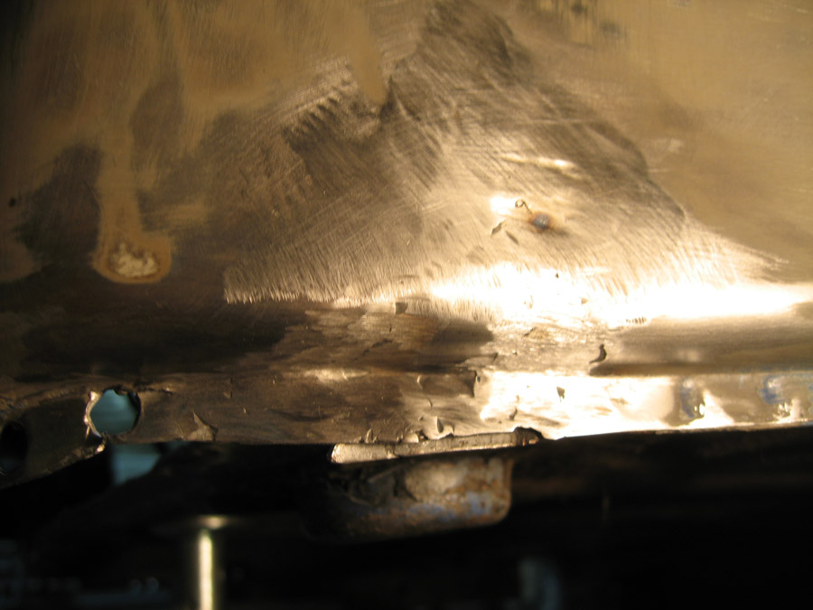 Inside again. 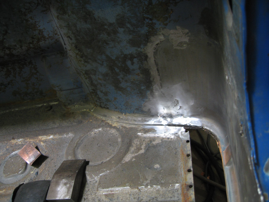 I will lead in to a post on work on the floor... (IMG:style_emoticons/default/type.gif) |
| nathansnathan |
 Sep 10 2013, 11:00 PM Sep 10 2013, 11:00 PM
Post
#146
|
|
Senior Member    Group: Members Posts: 1,052 Joined: 31-May 10 From: Laguna Beach, CA Member No.: 11,782 Region Association: None |
So, I had actually bolted everything together and done a test fit. I decided to cut the firewall at a diagonal and cut out the front half of the passenger floor so the whole assembly can slide in.
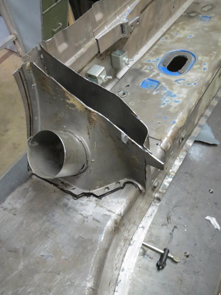 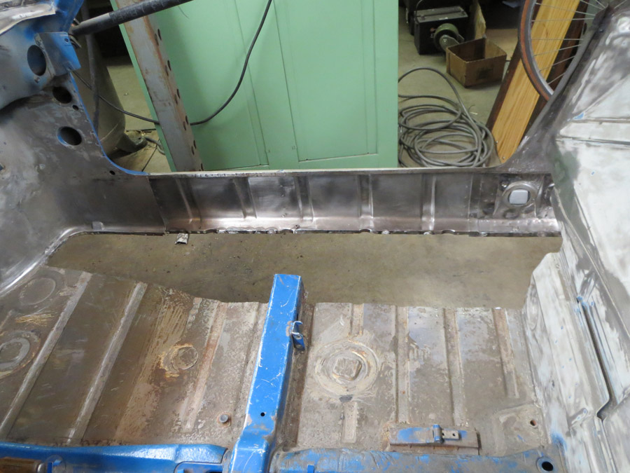 (IMG:style_emoticons/default/happy11.gif) :clampsandbolts: 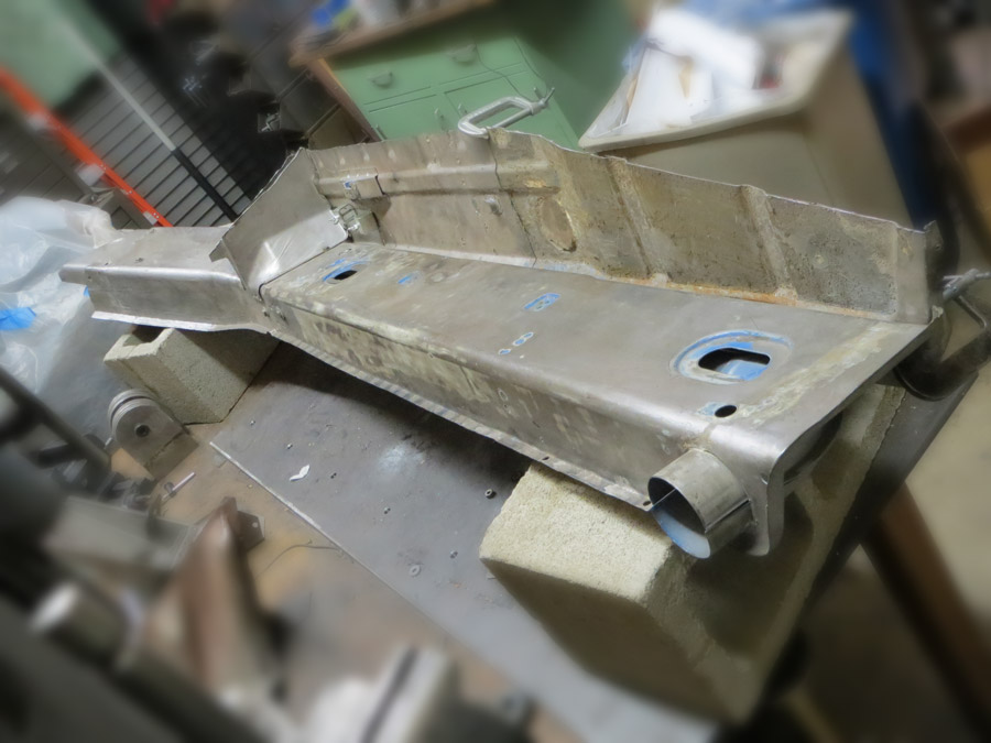 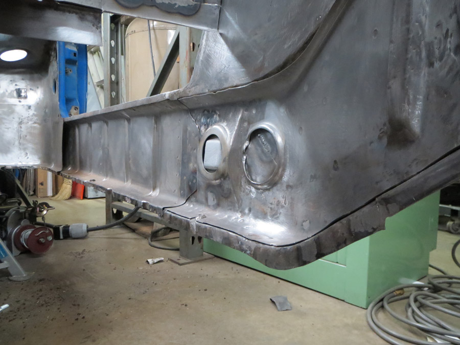 (IMG:style_emoticons/default/idea.gif) (IMG:style_emoticons/default/smoke.gif) (IMG:style_emoticons/default/stromberg.gif) 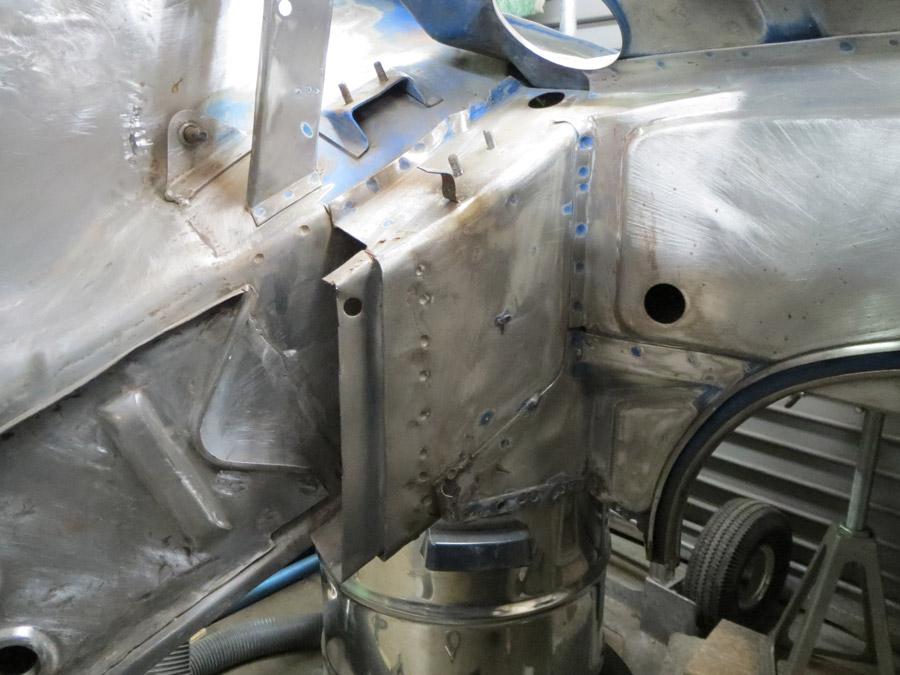 Oh yeah, the floor.... (IMG:style_emoticons/default/type.gif) ... |
| nathansnathan |
 Sep 10 2013, 11:21 PM Sep 10 2013, 11:21 PM
Post
#147
|
|
Senior Member    Group: Members Posts: 1,052 Joined: 31-May 10 From: Laguna Beach, CA Member No.: 11,782 Region Association: None |
An old pic here...
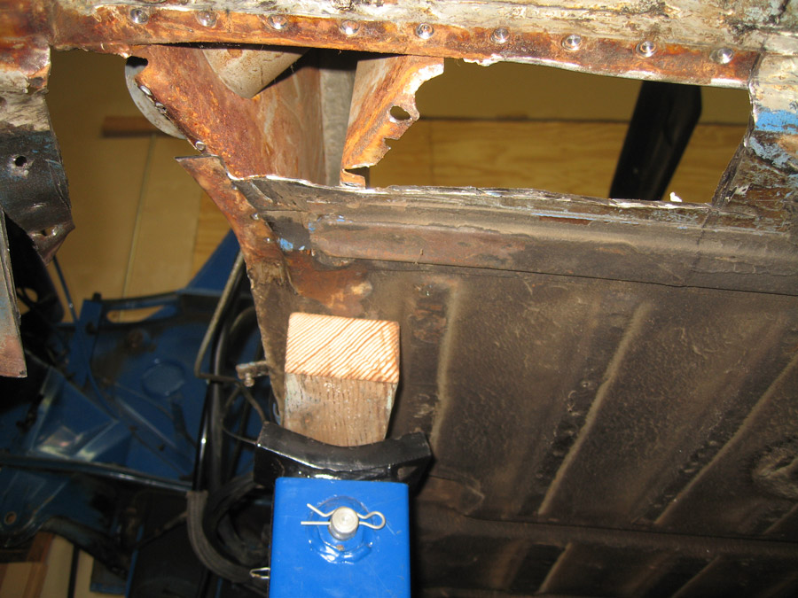 I got a spot welder so I need to fill in all the holes. I had thought about plug welding it using the holes, but the tig doesn't like the weld through very much. I think it will have a smaller burn area as the weld thru primer goes, between the panels. The floor, firewall, etc, in pieces... 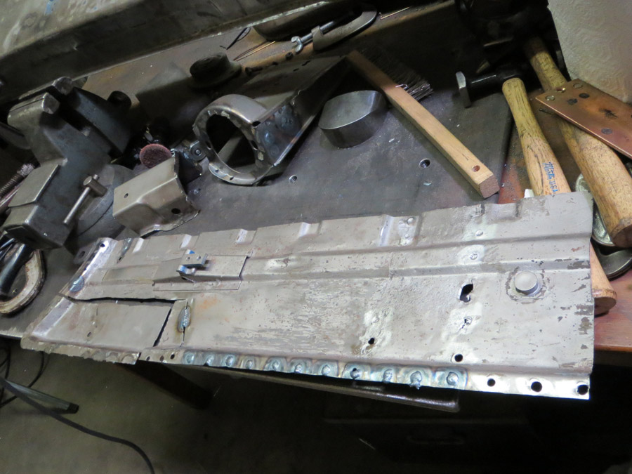 I was quite a butcher at the beginning. 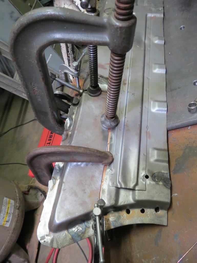 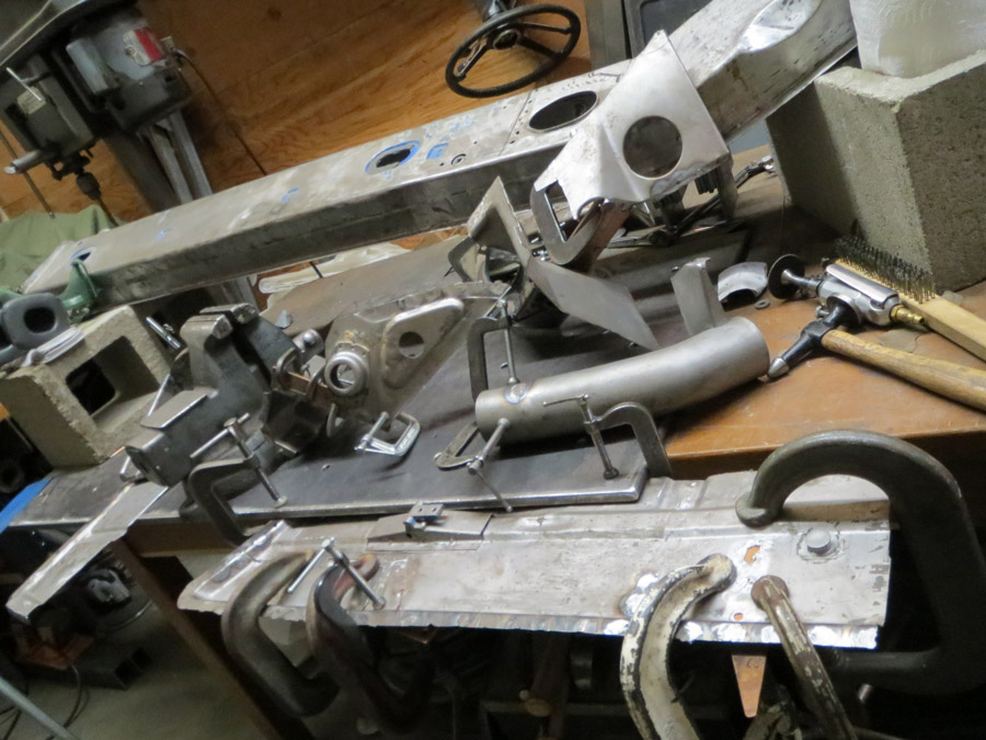 (IMG:style_emoticons/default/welder.gif) (IMG:style_emoticons/default/smash.gif) weld grind weld grind sand. I am using a mini pnuematic strait die grinder with a 1/4" arbor with a 1 1/2 inch x .040" grinding wheel to take it down just proud, and then a right angle mini die grinder with a 1/4 inch arbor also, and roloc pad. I use a conditioning pad before welding, and then after the grinding, an 80 grit sand paper pad to smooth it. THere are 100's of welds to fill in between the long, floor, firewall pieces, etc. 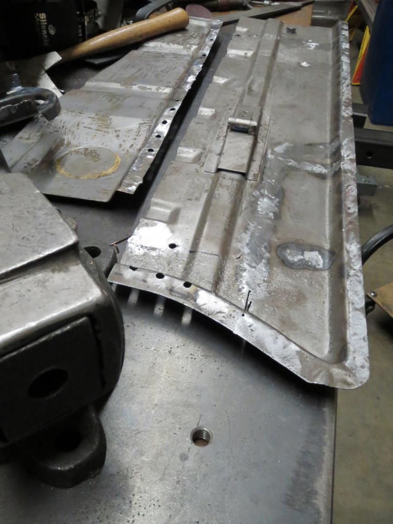 and... still some more to do... 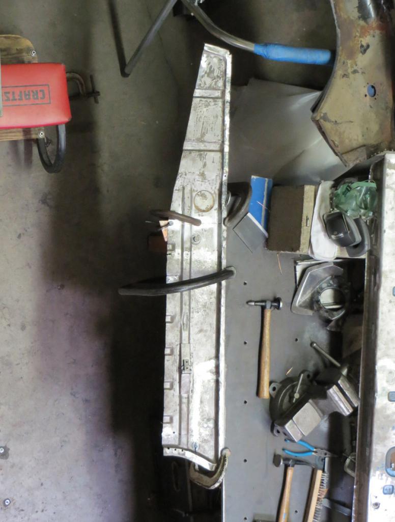 |
| SirAndy |
 Sep 11 2013, 12:52 PM Sep 11 2013, 12:52 PM
Post
#148
|
|
Resident German                          Group: Admin Posts: 41,894 Joined: 21-January 03 From: Oakland, Kalifornia Member No.: 179 Region Association: Northern California |
|
| cary |
 Dec 15 2013, 11:45 AM Dec 15 2013, 11:45 AM
Post
#149
|
|
Advanced Member     Group: Members Posts: 3,900 Joined: 26-January 04 From: Sherwood Oregon Member No.: 1,608 Region Association: Pacific Northwest 
|
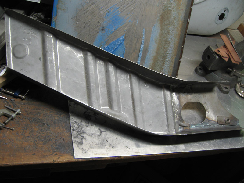
Nathan how did you build/create the corrugations?
 |
| cwpeden |
 Dec 15 2013, 11:53 AM Dec 15 2013, 11:53 AM
Post
#150
|
|
Great White North, huh?    Group: Members Posts: 916 Joined: 20-August 06 From: Victoria BC Member No.: 6,693 Region Association: Canada |
This is the easy way: http://www.restoration-design.com/mm5/merc...oduct_Code=P351
|
| cary |
 Dec 15 2013, 02:11 PM Dec 15 2013, 02:11 PM
Post
#151
|
|
Advanced Member     Group: Members Posts: 3,900 Joined: 26-January 04 From: Sherwood Oregon Member No.: 1,608 Region Association: Pacific Northwest 
|
I already have that installed. The RD piece was designed to be a one piece repair section. The factory design of the inner wheelhouse long was two layers. The outer portion everyone sees is a solid metal u shaped channel. Inside of that is the corrugated section that Nathan built. It adds to the strength of the structure.
Too add to complexity, the original factory was one piece. I want the corrugated piece to strengthen the welded joint. |
| cary |
 Dec 15 2013, 02:20 PM Dec 15 2013, 02:20 PM
Post
#152
|
|
Advanced Member     Group: Members Posts: 3,900 Joined: 26-January 04 From: Sherwood Oregon Member No.: 1,608 Region Association: Pacific Northwest 
|
Here's a picture of what you get when you have the two RD pieces ready to install.
If you look at the RD wheelhouse you'll see it has flanges so it can be welded to the inner fender. One piece design. 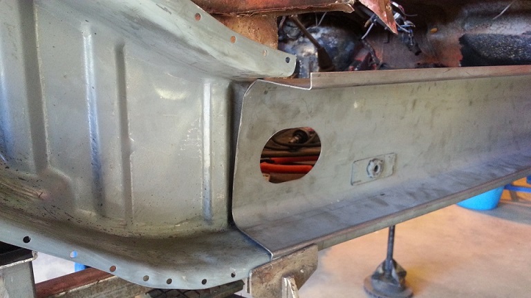 The piece Nathan built would lay inside those two piece. The seat belt nut plate would need to be removed. |
| scotty b |
 Dec 15 2013, 02:35 PM Dec 15 2013, 02:35 PM
Post
#153
|
|
rust free you say ?                Group: Members Posts: 16,375 Joined: 7-January 05 From: richmond, Va. Member No.: 3,419 Region Association: None |
All of Nathans parts are either original or R.D. You have the inner long attached properly. Buy the inner rocker, it is the piece with the ribs. the flanges of the 2 are spot welded together to form a rectangular box. There is only one layer for most of the length of the long, inside and out. There is a second smooth piece that covers where the kickup into the engine bay is, but no one makes that, and AFAIK no one ever has. Not sure why, as it is a appearance piece that alwaysgoes along with the repair
|
| nathansnathan |
 Dec 15 2013, 04:46 PM Dec 15 2013, 04:46 PM
Post
#154
|
|
Senior Member    Group: Members Posts: 1,052 Joined: 31-May 10 From: Laguna Beach, CA Member No.: 11,782 Region Association: None |
It's complicated to explain, "inside-outer", etc, so I made a diaagram. (IMG:style_emoticons/default/biggrin.gif)
I was thinking this is the best way to describe it. 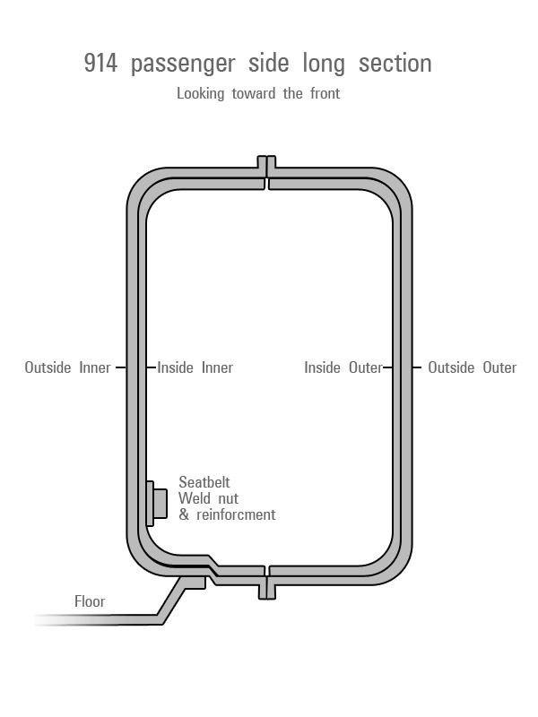 Both inner and outer are double layered from just forward of the lower seat belt bolt until they reach the trunk, but people claim that the 1 piece rd is thicker and is to be used instead of both layers from the firewall back. I chose not to do it that way. I would rather it be smooth, and I think 2 layers would be stiffer there, just better overall. So I attached the stock inside inner piece forward of the firewall, to the RD corrugated piece. I'd posted this pic in post 109, I used a radius from the top of the long and corrugations from the bottom of the driver side of the donor car to remake the bottom. (IMG:http://www.914world.com/bbs2/uploads/post-11782-1327778514.jpg) |
| cary |
 Dec 15 2013, 05:21 PM Dec 15 2013, 05:21 PM
Post
#155
|
|
Advanced Member     Group: Members Posts: 3,900 Joined: 26-January 04 From: Sherwood Oregon Member No.: 1,608 Region Association: Pacific Northwest 
|
I'm a little slow, but I'm getting it.
1. Scotty. I have a four pieces of new RD. Inner Long, Long, Inner Rocker and Inner Wheelhouse. 2. So to copy Nathan, I would build the extension on to the inner long to get a longer box and tie? Looks like it would need to lapped so it would slide inside the new RD long? 3. Looks like there's multiple ways to skin this cat. 4. Then build the box to cover the inner long inside the engine compartment. 5. I still don't like the firewall, long and inner long coming together in the same spot. Adding Nathan's extension helps a little. Anal ................. |
| nathansnathan |
 Dec 15 2013, 05:36 PM Dec 15 2013, 05:36 PM
Post
#156
|
|
Senior Member    Group: Members Posts: 1,052 Joined: 31-May 10 From: Laguna Beach, CA Member No.: 11,782 Region Association: None |
I have been meaning to post progress.
I cut out more at the back of the long. I am planning to splice it back together at one of the inside's corrugations so I can weld the inside, and then a patch to the outer to seal that up, that little piece there. 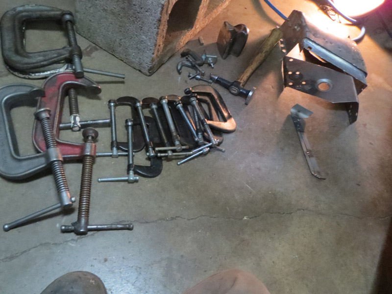 You can't go all the way back or the engine shelf becomes complicated at the corner. 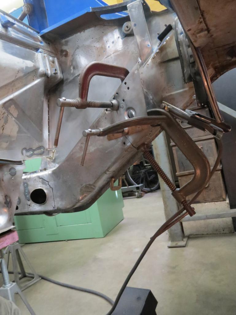 Here, attaching the piece that was going to be the patch, but the plan changed. I am trying to attach the suspension console to the long, build the whole thing and then spot weld it all in as 1 big piece, maybe even the engine shelf with it. Pieces I cut out, inside and outside inner. It curves there, toward the outside, just rearward of the suspension console. 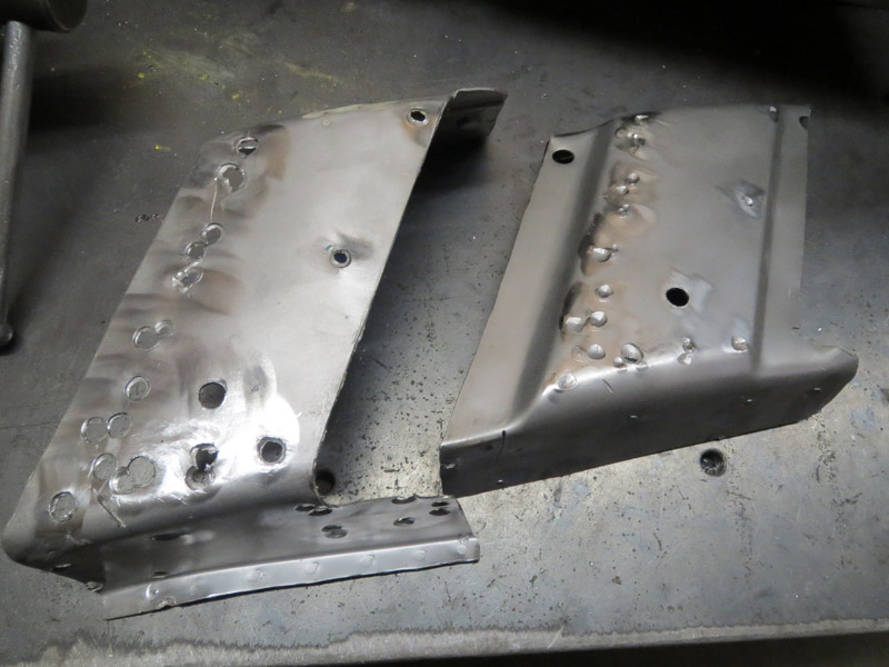 Fitting it up to put the next piece on. [this wants to be at the end of the post for some reason] Welding the inside to the RD piece. I had cut some of it off before. The outer didn't want to let it sit right, but I wanted to make sure it would go together right so this is how I got it all set up to weld. 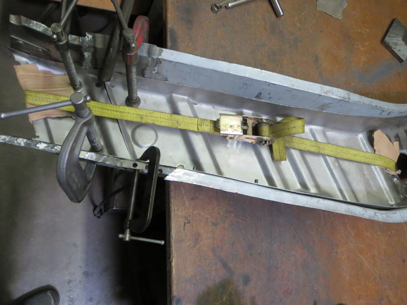 Got it tacked 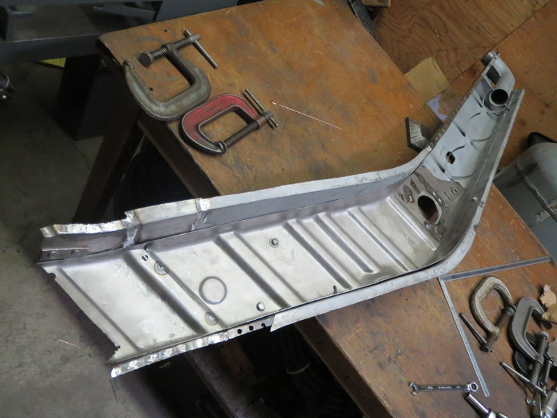 and ready to fit. Some 1/4-20 bolts holding it together. 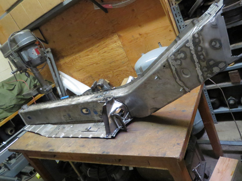 I put the rear up first and pop it in up front over the lip that sits at the base of the front wheel well. 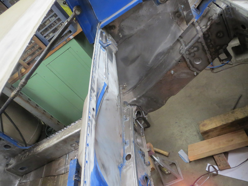 I bolted the floor in wrong, so the gap is big at the front, should have measured. I'm going to fit this again, trying it with the engine shelf attached. I can pivot it in. I will add the forward piece of the firewall, too. I think I need to cut the support under the seat at and angle to make this work for fitting 2, to come. 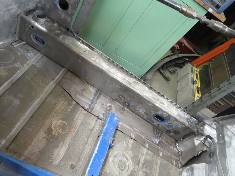 My other ride has been taking my time, discovered some nasty rust under the front bumper. I've been dividing up my 3 hours a day to work on these things. This is how I've driven my bus to work the past week and a half. I oil it up everyday, I've been using penatrol, which is like an oil paint additive that smells like linseed oil, hasn't rusted yet. No ticket for the license plate. (IMG:style_emoticons/default/biggrin.gif) 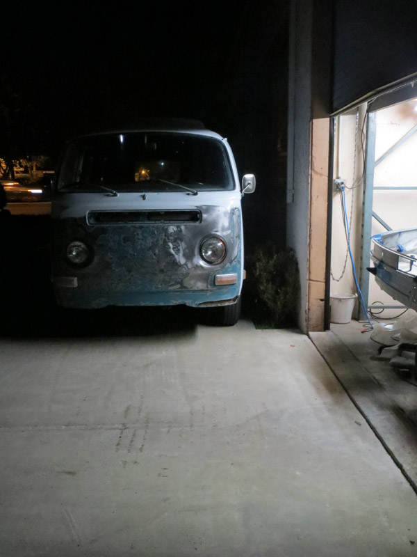 Attached image(s) 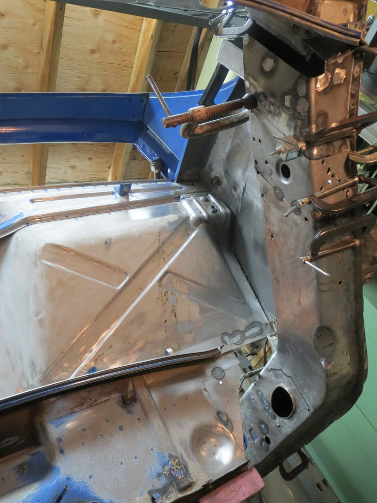 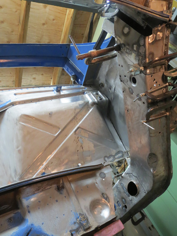
|
| trojanhorsepower |
 Dec 15 2013, 06:32 PM Dec 15 2013, 06:32 PM
Post
#157
|
|
Senior Member    Group: Members Posts: 867 Joined: 21-September 03 From: Marion, NC Member No.: 1,179 Region Association: None |
Look'in good!
|
| ONTHEGRIND |
 Dec 15 2013, 08:32 PM Dec 15 2013, 08:32 PM
Post
#158
|
|
Member   Group: Members Posts: 286 Joined: 10-November 08 From: California Member No.: 9,738 Region Association: None |
How much of the inner long is double walled Im currently in the process of replacing my rear pans and the bottom of my inner longs have some rust and pitting .. Im trying to figure the best way to repair before I weld the floors in place..in my photo you can see some minor rust where the pans sits against the long but on the outside the metal looks fairly fresh..
Should I weld the holes closed and put the pan in or cut out the bad stuff and patch in a new piece If its double walled the inner piece is un rusted as I can see down in the there (IMG:http://www.914world.com/bbs2/uploads_offsite/img.photobucket.com-9738-1387161142.1.jpg) |
| gothspeed |
 Dec 15 2013, 10:07 PM Dec 15 2013, 10:07 PM
Post
#159
|
|
Senior Member    Group: Members Posts: 1,539 Joined: 3-February 09 From: SoCal Member No.: 10,019 Region Association: None |
This thread is awesome!!! Hats off to all the effort displayed!!! (IMG:style_emoticons/default/smilie_pokal.gif)
|
| cary |
 Dec 15 2013, 11:13 PM Dec 15 2013, 11:13 PM
Post
#160
|
|
Advanced Member     Group: Members Posts: 3,900 Joined: 26-January 04 From: Sherwood Oregon Member No.: 1,608 Region Association: Pacific Northwest 
|
What you're working on right now is the long. The inner long is the continuation of the same piece that goes up the wheel well in the engine compartment.
It only has a small section that is double layered. In the blue box. 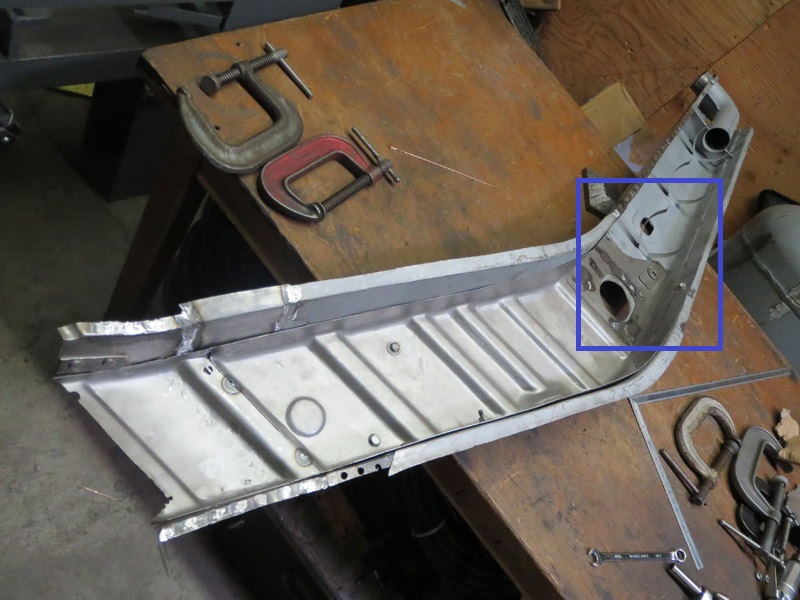 But to answer the original question. The portion outlined below in blue is the actual inner layer that Nathan exposed after he removed the outer layer. It does go further up the inner long but I can't remember exactly where it stops. 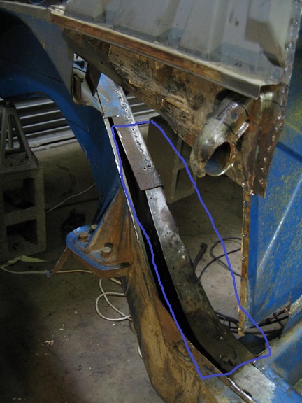 I'm going exit before I get run out of town for being a hijacker. LOL. |
  |
42 User(s) are reading this topic (42 Guests and 0 Anonymous Users)
0 Members:

|
Lo-Fi Version | Time is now: 25th November 2024 - 03:43 AM |
Invision Power Board
v9.1.4 © 2024 IPS, Inc.


