|
|

|
Porsche, and the Porsche crest are registered trademarks of Dr. Ing. h.c. F. Porsche AG.
This site is not affiliated with Porsche in any way. Its only purpose is to provide an online forum for car enthusiasts. All other trademarks are property of their respective owners. |
|
|
  |
| Mike Bellis |
 Jun 12 2015, 08:58 PM Jun 12 2015, 08:58 PM
Post
#367
|
|
Resident Electrician      Group: Members Posts: 8,346 Joined: 22-June 09 From: Midlothian TX Member No.: 10,496 Region Association: None 

|
Oh and the rear will be on the cv adapter trans side. If you go with something like this http://www.pacificcustoms.com/mm5/merchant...r-drive-flanges I have 3/16" magnets for you to embed. I think I have 12 left over, 3/8" long. |
| Andyrew |
 Jun 12 2015, 09:15 PM Jun 12 2015, 09:15 PM
Post
#368
|
|
Spooling.... Please wait           Group: Members Posts: 13,377 Joined: 20-January 03 From: Riverbank, Ca Member No.: 172 Region Association: Northern California 
|
Based on my understanding most abs systems have the magnet on the sensor side, but Ill let you know! The spacer/adapter will be custom milled I suspect.
|
| Andyrew |
 Jun 13 2015, 02:25 AM Jun 13 2015, 02:25 AM
Post
#369
|
|
Spooling.... Please wait           Group: Members Posts: 13,377 Joined: 20-January 03 From: Riverbank, Ca Member No.: 172 Region Association: Northern California 
|
Playing around with the tire calculator I realized that I can use a 245/45/17 tire up front instead of the 245/40/17 tire currently up front and all of a sudden the front/rear ratio is perfect vs being 1" off.... I'll keep this in the back of my brain as I go through the ABS stuff... This might let me use stock Porsche ABS rings in the rear vs milling my own rear rings (an extra 5% more slots to compensate)
I'll have to see what I can come up with for that. I also found out some different ABS ring sizes that I can pick up so I might just mill that into my spacer for my CV's (should be relatively easy, make the OD on the spacer the same as the ID on the ABS ring, weld on.) |
| JRust |
 Jun 13 2015, 06:46 PM Jun 13 2015, 06:46 PM
Post
#370
|
|
914 Guru      Group: Members Posts: 6,310 Joined: 10-January 03 From: Corvallis Oregon Member No.: 129 Region Association: Pacific Northwest 
|
(IMG:style_emoticons/default/WTF.gif) Andrew I gotta say. My head hurts just reading about all that wiring (IMG:style_emoticons/default/confused24.gif)
I don't have the patience to do all you are doing. You & Mike are "Nuckin Futs" man. My kind of people of course (IMG:style_emoticons/default/evilgrin.gif) . Watching your thread to see this come together. Going to be sweet. Can't wait to go for a ride in it |
| Mike Bellis |
 Jun 13 2015, 06:48 PM Jun 13 2015, 06:48 PM
Post
#371
|
|
Resident Electrician      Group: Members Posts: 8,346 Joined: 22-June 09 From: Midlothian TX Member No.: 10,496 Region Association: None 

|
|
| Andyrew |
 Jun 13 2015, 10:34 PM Jun 13 2015, 10:34 PM
Post
#372
|
|
Spooling.... Please wait           Group: Members Posts: 13,377 Joined: 20-January 03 From: Riverbank, Ca Member No.: 172 Region Association: Northern California 
|
(IMG:style_emoticons/default/WTF.gif) Andrew I gotta say. My head hurts just reading about all that wiring (IMG:style_emoticons/default/confused24.gif) I don't have the patience to do all you are doing. You & Mike are "Nuckin Futs" man. My kind of people of course (IMG:style_emoticons/default/evilgrin.gif) . Watching your thread to see this come together. Going to be sweet. Can't wait to go for a ride in it I think Mike is a bit more nutz than I am to be honest! His wiring was way more difficult than what mine will end up being, and his whole car is just way more off the wall (In a good way)! My wiring will be limited to plug and play. The MOST difficult thing will be figuring out the lights and a solution to the headlight relay. It WILL take a while for me to run the wires and eliminate the non essentials but the whole system can run with pretty much everything I am not going to be using removed. The more difficult bits here will be the ABS fabrication, brake line fabrication, and figuring out the correct position of the stability control sensors and possibly tuning that code (Never heard of anyone doing it... so that will be SUPER difficult.. Luckily it can be switched off until its sorted out). However all of that relies on someone actually buying the current v8 engine setup... I am at the point where I am getting anxious to put the 4 cylinder engine in place and start mocking everything up.. I can do a lot of wiring research in the meantime for what does what on the wiring harness and I still need to get my hands on a body harness.... I grabbed this and some other bits from my dads place.. This water pump should make a nice air to water intercooler pump. Pretty sure a lot of guys use this type of pump for this function. 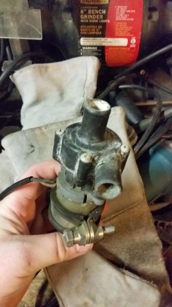 |
| Mike Bellis |
 Jun 13 2015, 10:56 PM Jun 13 2015, 10:56 PM
Post
#373
|
|
Resident Electrician      Group: Members Posts: 8,346 Joined: 22-June 09 From: Midlothian TX Member No.: 10,496 Region Association: None 

|
I don't yet know what your donor car will be to get the body harness... When I did mine I went here: https://erwin.vw.com/erwin/showHome.do, paid a $35 for 24 hour access and downloaded every document VW ever made for my donor VIN. Well worth it. Full body wiring diagrams, tech articles, manuals, etc...
I don't know if Audi has a similar website but this was the best $35 I ever spent. I bet I downloaded 100 files or more. |
| Andyrew |
 Jun 13 2015, 11:14 PM Jun 13 2015, 11:14 PM
Post
#374
|
|
Spooling.... Please wait           Group: Members Posts: 13,377 Joined: 20-January 03 From: Riverbank, Ca Member No.: 172 Region Association: Northern California 
|
Hmm.. Very interesting. This is what I've been looking for..
Mind sending me an example of one of the wiring harnesses so I can see what they have? Or just posting a pic of it here? |
| Andyrew |
 Jun 13 2015, 11:16 PM Jun 13 2015, 11:16 PM
Post
#375
|
|
Spooling.... Please wait           Group: Members Posts: 13,377 Joined: 20-January 03 From: Riverbank, Ca Member No.: 172 Region Association: Northern California 
|
I've been downloading some diagrams from the parts book, but there is no wiring charts or anything...
http://www.partscats.info/audi/en/?i=cat_v...567890&hg=9 |
| Andyrew |
 Jun 14 2015, 12:08 AM Jun 14 2015, 12:08 AM
Post
#376
|
|
Spooling.... Please wait           Group: Members Posts: 13,377 Joined: 20-January 03 From: Riverbank, Ca Member No.: 172 Region Association: Northern California 
|
One hour later and I've downloaded all there is to be known for the B5 A4 chassis.. Thanks Mike! This surely will be a help.
|
| Andyrew |
 Jun 14 2015, 12:48 AM Jun 14 2015, 12:48 AM
Post
#377
|
|
Spooling.... Please wait           Group: Members Posts: 13,377 Joined: 20-January 03 From: Riverbank, Ca Member No.: 172 Region Association: Northern California 
|
Been reading up on the stability control system and its requirements for the past 30 minutes... (IMG:style_emoticons/default/smile.gif)
Its doable! Requires more bits than I thought but still doable! |
| Andyrew |
 Jul 6 2015, 09:08 AM Jul 6 2015, 09:08 AM
Post
#378
|
|
Spooling.... Please wait           Group: Members Posts: 13,377 Joined: 20-January 03 From: Riverbank, Ca Member No.: 172 Region Association: Northern California 
|
Had a couple weeks of no progress due to a vacation but I am back on it slowly!
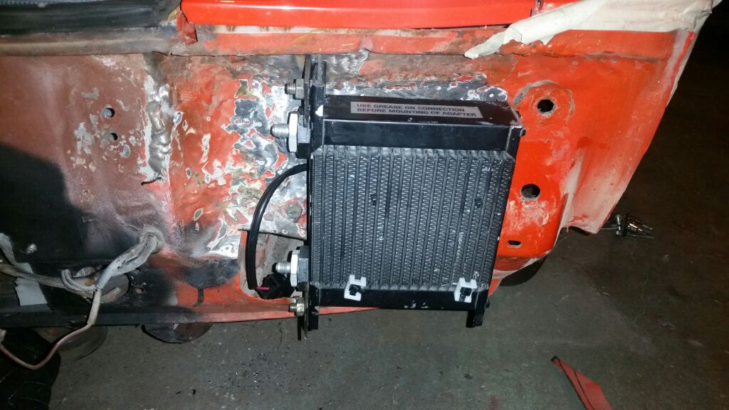
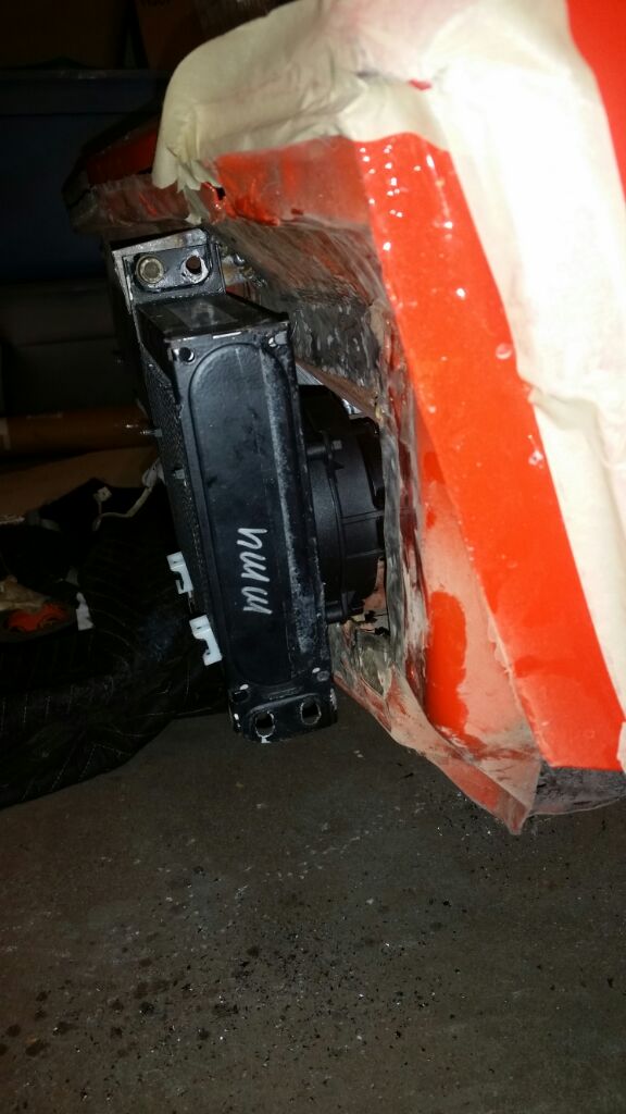
Got an oil cooler and fan, currently have it hard mounted, but am debating putting some rubber in between the metal. I still have one tab left to weld but ran out of time tonight. I have the smallest SPAL fan behind it that fits nicely in the cubby I made. I will be using some foam between the oil cooler and the body to make a nice seal to the area below the headlight and cutting slits in the front of the fender well (directly behind the oil cooler) for the air escape and finally closing off the area under the headlights so air passes through cleanly. Lines will be run basically straight back to the engine, likely in either the center tunnel or possibly in the dr side rocker. Since I am keeping the factory oil-water cooler I dont need much of an external oil cooler. Still debating on line size but I might try to run 8-an if anyone knows of a pressure loss calculator for AN lines let me know. |
| Andyrew |
 Jul 6 2015, 09:09 AM Jul 6 2015, 09:09 AM
Post
#379
|
|
Spooling.... Please wait           Group: Members Posts: 13,377 Joined: 20-January 03 From: Riverbank, Ca Member No.: 172 Region Association: Northern California 
|
  |
| Andyrew |
 Jul 12 2015, 11:17 PM Jul 12 2015, 11:17 PM
Post
#380
|
|
Spooling.... Please wait           Group: Members Posts: 13,377 Joined: 20-January 03 From: Riverbank, Ca Member No.: 172 Region Association: Northern California 
|
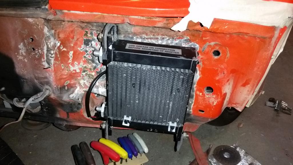 Finished the mounting of the oil cooler and added a little padding. 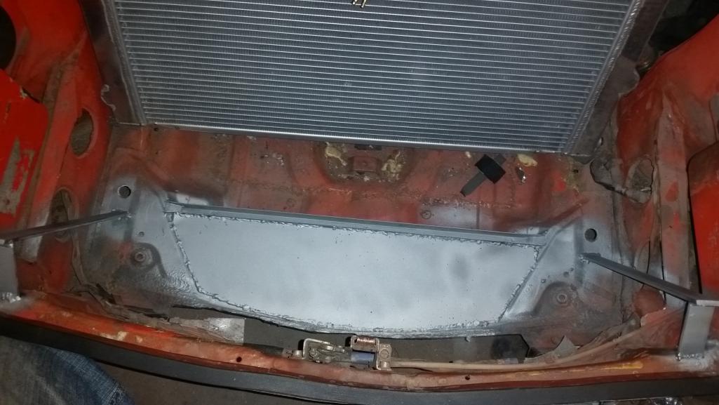 Here you can see the beginning of the radiator mount, 1/8" bar makes up the radiator vertical support, the bit holes in the floor will be tig welded later to bring the strength back. Thats where the lower radiator mounts sit. There is a steel 5/8 x 5/8 U channel (commercial window glass stop....) that the lower portion vertical portion of the radiator sits in allowing for no air flow past the radiator. The floor is 16ga steel fully welded. Then everything is hit with zinc galvy. 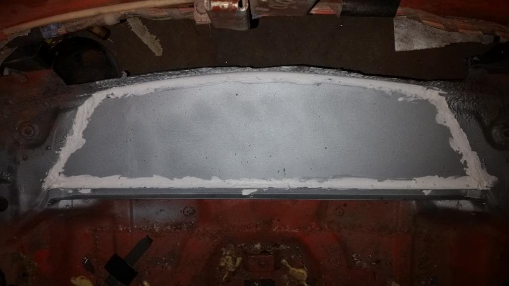 And the weld joints hit with calking. 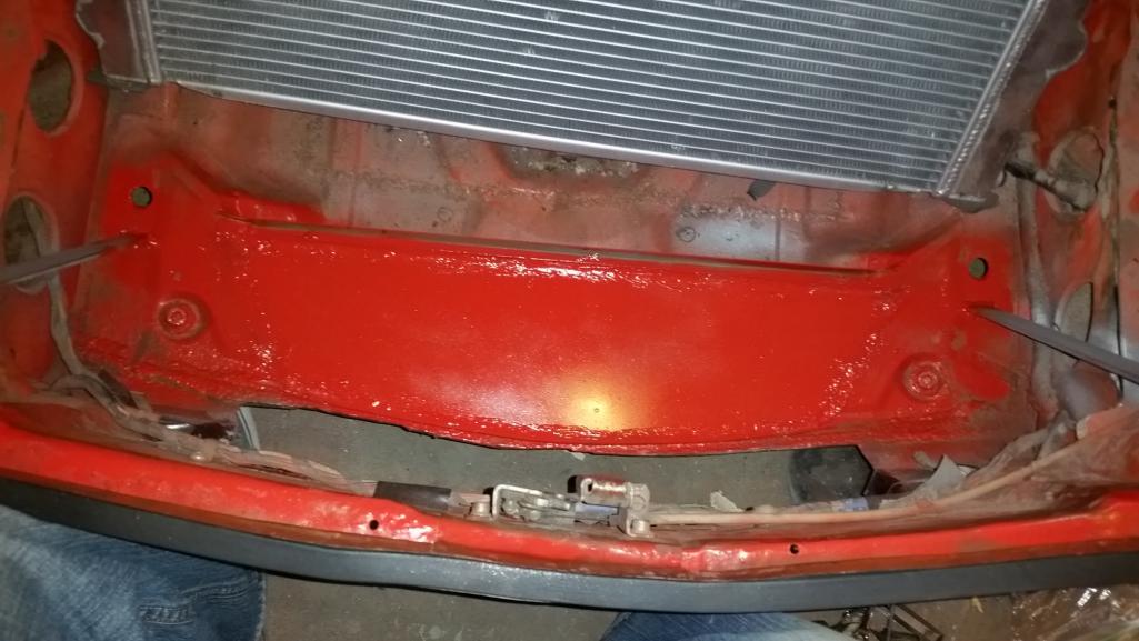 And painted rattle can. |
| Andyrew |
 Jul 12 2015, 11:22 PM Jul 12 2015, 11:22 PM
Post
#381
|
|
Spooling.... Please wait           Group: Members Posts: 13,377 Joined: 20-January 03 From: Riverbank, Ca Member No.: 172 Region Association: Northern California 
|
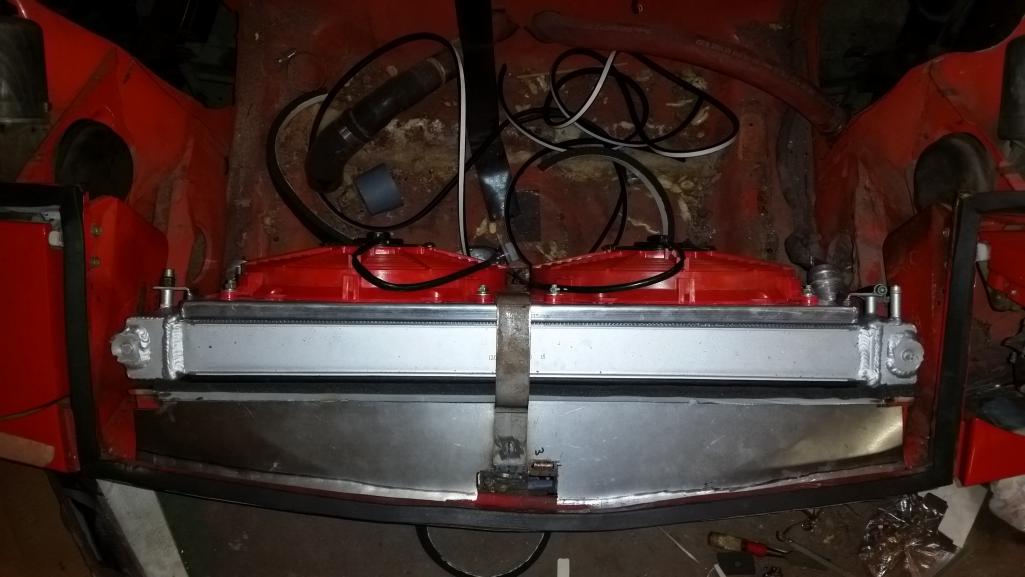 Finally the upper section is built. The vertical radiator supports are joined by another piece of 5/8x5/8 U channel steel (glass stop). for the radiator to sit on. We have some bulb seal on the radiator and some foam seal on the radiator support. Vertical gaps are taken up with foam seal (weatherstripping). The upper section is more 16ga steel and I am debating on tack welding it, but I most likely will bolt it down with bulb seal underneath. Vertical gaps have not been taken into account yet as I havent bought my AC condenser yet. And I am testing with using the strap in the middle to hold everything down or build straps on each side that connect to the factory mount tabs that I hacked off a bit to much. Still more thinking to do here. |
| Chris H. |
 Jul 13 2015, 12:17 PM Jul 13 2015, 12:17 PM
Post
#382
|
|
Senior Member     Group: Members Posts: 4,048 Joined: 2-January 03 From: Chicago 'burbs Member No.: 73 Region Association: Upper MidWest 
|
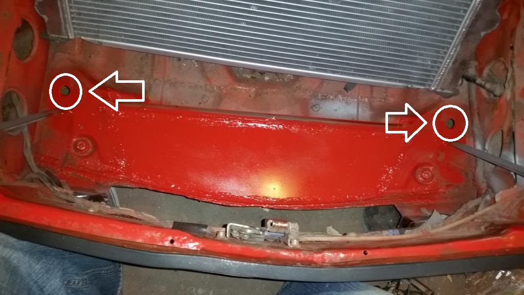
Good start. That's gonna work well for you. I like how close you put the rad to the front of the trunk. Question...When you drilled the holes circled below did they go all the way through the trunk floor or not? It doesn't look like it. When I set mine up it looked like there were 2 layers of metal there with a gap in between but was too chicken to try drilling them out (IMG:style_emoticons/default/smile.gif) .
 |
| Andyrew |
 Jul 13 2015, 01:11 PM Jul 13 2015, 01:11 PM
Post
#383
|
|
Spooling.... Please wait           Group: Members Posts: 13,377 Joined: 20-January 03 From: Riverbank, Ca Member No.: 172 Region Association: Northern California 
|
The goal was to put it as close to the front as possible. Yes I did drill through both layers which is why I want to tig the holes.. (IMG:style_emoticons/default/sad.gif)
|
| Chris H. |
 Jul 13 2015, 01:26 PM Jul 13 2015, 01:26 PM
Post
#384
|
|
Senior Member     Group: Members Posts: 4,048 Joined: 2-January 03 From: Chicago 'burbs Member No.: 73 Region Association: Upper MidWest 
|
So could I theoretically drill through ONE layer and have enough space to drop the rad mounts and hold the rad in place or are the two layers of metal right on top of each other?
On the bottom of mine I have a piece of sheet metal with mounts in it similar to the renegade setup but it doesn't get the radiator as low as yours so I can't get it as close to the front. I'm going to slightly trim the top mounts which will give me a bit more clearance. |
| Andyrew |
 Jul 13 2015, 02:20 PM Jul 13 2015, 02:20 PM
Post
#385
|
|
Spooling.... Please wait           Group: Members Posts: 13,377 Joined: 20-January 03 From: Riverbank, Ca Member No.: 172 Region Association: Northern California 
|
They were within about 1/8" of each other(I'll take a pic tonight), If you cut the bottom of the radiator tabs down that much theoretically yes you could, but I dont think it would realistically work especially with how much you have to tilt the radiator at that point to make it fit.
|
| Chris H. |
 Jul 13 2015, 06:43 PM Jul 13 2015, 06:43 PM
Post
#386
|
|
Senior Member     Group: Members Posts: 4,048 Joined: 2-January 03 From: Chicago 'burbs Member No.: 73 Region Association: Upper MidWest 
|
Interesting...good to know.
Here are some pics of my setup in case it gives you any ideas to use. Ignore the wires taped to the floor. I'll move those later this year but it requires taking the entire system out which I don't feel like doing yet. 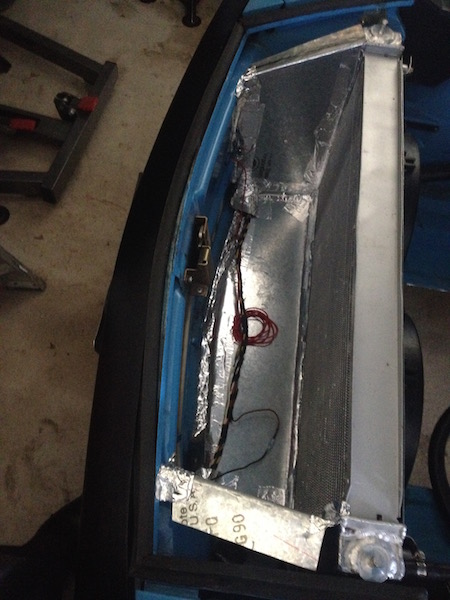 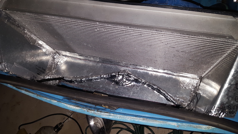 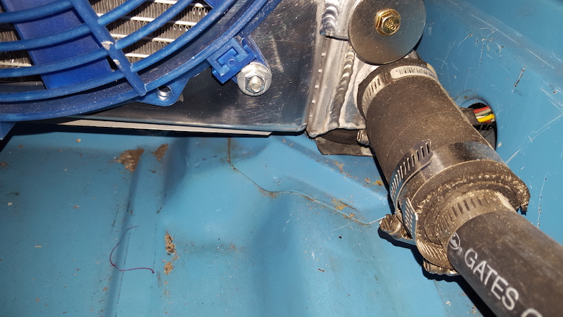 On the bottom There is a piece of sheet metal that is attached at the front to the former stock valance mounting holes. At the radiator there is a 90 degree lip bent upward about a half inch or so across and the radiator is bolted to it. at the very ends the metal extends another couple of inches and I installed rubber mounts to them which the radiator sits in. 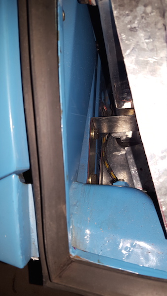 It's a '75 so at the very front of the car there are a couple of nubs that dictate where your side panels that funnel air to the radiator can be. Since I was pretty sure I'd be playing with the setup I bent a couple of u-shaped pieces and attached them with the stock bumper shock bolts. That way no holes drilled or welds. They're in there good and there's downward pressure on the bottom piece. Most important thing is to get ALL the air to go through the rad. 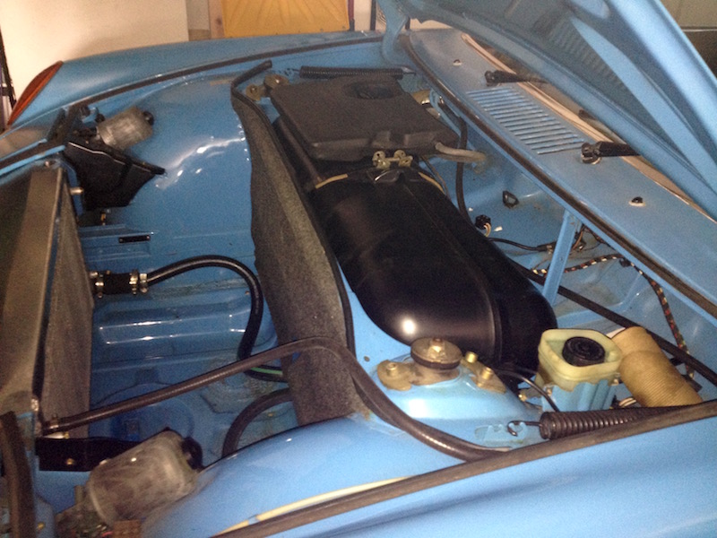 The top piece which you can see in this pic slides in just underneath the hood seal channel pretty tightly. The back edge is bent so that is can be attached to the radiator at the mounting holes. When it's fully in place the radiator doesn't move AT ALL, but my plan is to put some fasteners in the channel and small bolts on the attachment points on the radiator to make sure it doesn't work its way loose over time. I'd still like to get the rad setup closer to the front, but for now I'm gonna start driving it. |
  |
2 User(s) are reading this topic (2 Guests and 0 Anonymous Users)
0 Members:

|
Lo-Fi Version | Time is now: 26th November 2024 - 07:27 AM |
Invision Power Board
v9.1.4 © 2024 IPS, Inc.


