|
|

|
Porsche, and the Porsche crest are registered trademarks of Dr. Ing. h.c. F. Porsche AG.
This site is not affiliated with Porsche in any way. Its only purpose is to provide an online forum for car enthusiasts. All other trademarks are property of their respective owners. |
|
|
  |
| Lucky9146 |
 Jun 22 2016, 06:53 PM Jun 22 2016, 06:53 PM
Post
#101
|
|
Always Wanted A Bigger Go Cart    Group: Members Posts: 1,675 Joined: 22-September 14 From: Poway California Member No.: 17,942 Region Association: Southern California 
|
I have started to reseal and clean up the engine. I test fit the transmission to the engine and found that I will most likely need to shim the pivot point based on some previous posts on this. Unfortunately the clutch release bearing is frozen so I have to replace that too. They seem to be very expensive ($150+), are used release bearings worth considering? Jeff B Your transmission looks amazing! How did you get it to look that good? If you don't mind. |
| jkb944t |
 Jun 23 2016, 06:31 AM Jun 23 2016, 06:31 AM
Post
#102
|
|
Member   Group: Members Posts: 464 Joined: 17-January 05 From: Canton, OH Member No.: 3,459 Region Association: None |
I painted it with the paint shown in the picture below:
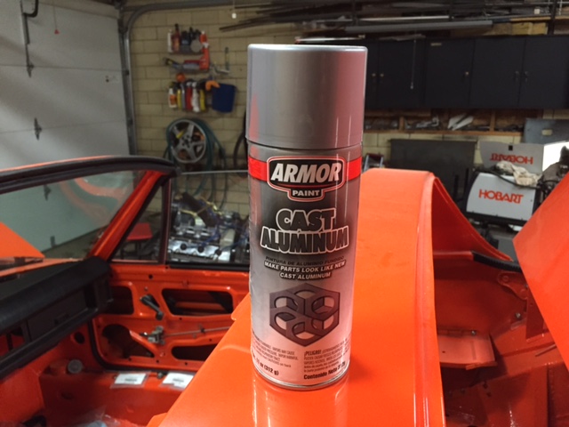 I should mention that it took a lot of prep work cleaning the transmission with a paint degreaser/wax remover. The paint itself went on very nicely once the transmission was cleaned up. Jeff B |
| jkb944t |
 Jul 19 2016, 06:03 AM Jul 19 2016, 06:03 AM
Post
#103
|
|
Member   Group: Members Posts: 464 Joined: 17-January 05 From: Canton, OH Member No.: 3,459 Region Association: None |
Finally installed the motor and tranny! This is definitely a milestone in the build sequence. I never imagined it would take this much time and effort to get to this point.
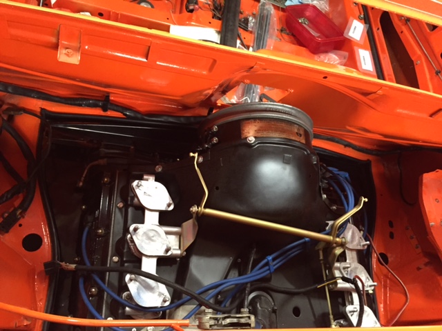 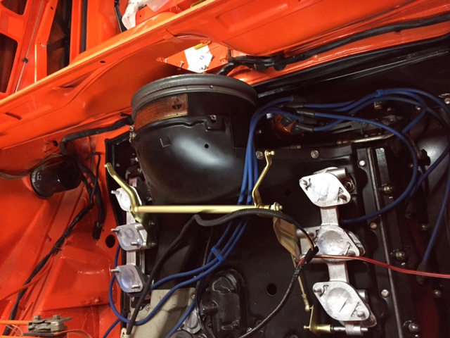 This is a picture of how the final battery tray came out once everything was bolted together. 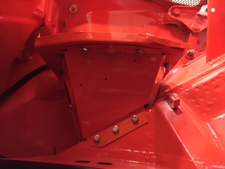 Still lots of work and small details to work through. Jeff B Attached image(s) 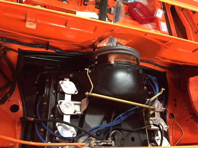
|
| jkb944t |
 Jul 21 2016, 11:00 AM Jul 21 2016, 11:00 AM
Post
#104
|
|
Member   Group: Members Posts: 464 Joined: 17-January 05 From: Canton, OH Member No.: 3,459 Region Association: None |
Started to get everything hooked up underneath the car.
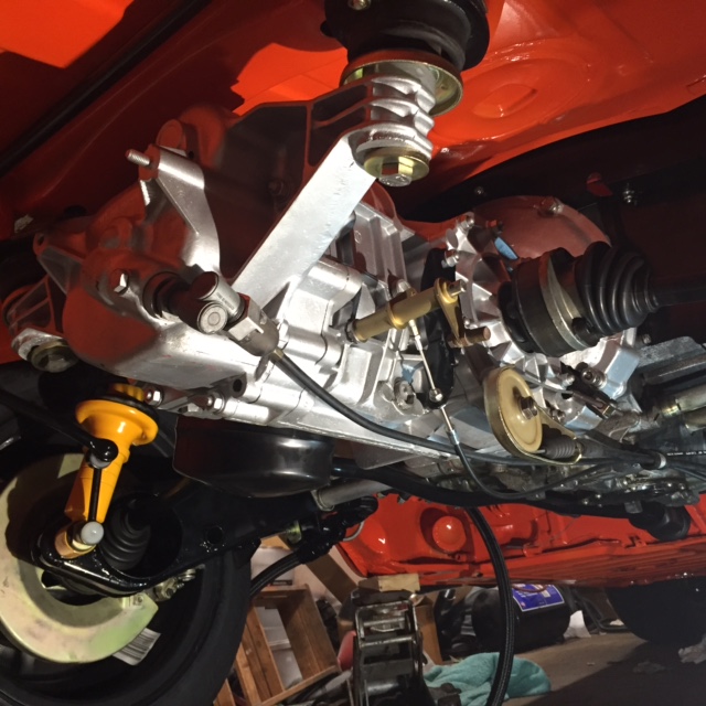 After spending so much time working out all the details on this car I now understand why people sell what I previously considered a nearly completed car! Jeff B |
| SixerJ |
 Jul 21 2016, 11:35 PM Jul 21 2016, 11:35 PM
Post
#105
|
|
Member   Group: Members Posts: 448 Joined: 24-June 13 From: UK Member No.: 16,042 Region Association: England |
Don't give up your doing a sterling job & car is looking fabulous and soon be (IMG:style_emoticons/default/driving.gif)
|
| altitude411 |
 Jul 22 2016, 01:12 AM Jul 22 2016, 01:12 AM
Post
#106
|
|
I drove my 6 into a tree    Group: Members Posts: 1,306 Joined: 21-September 14 From: montana Member No.: 17,932 Region Association: Rocky Mountains 
|
Stunning... (IMG:style_emoticons/default/shades.gif) Nice work.
|
| jkb944t |
 Aug 3 2016, 10:11 AM Aug 3 2016, 10:11 AM
Post
#107
|
|
Member   Group: Members Posts: 464 Joined: 17-January 05 From: Canton, OH Member No.: 3,459 Region Association: None |
I started to mount the relay panel last night and test fit the carburetors. The passenger side rain hat is awfully close to the rear trunk bulkhead. Not sure if this tight clearance is normal or not.
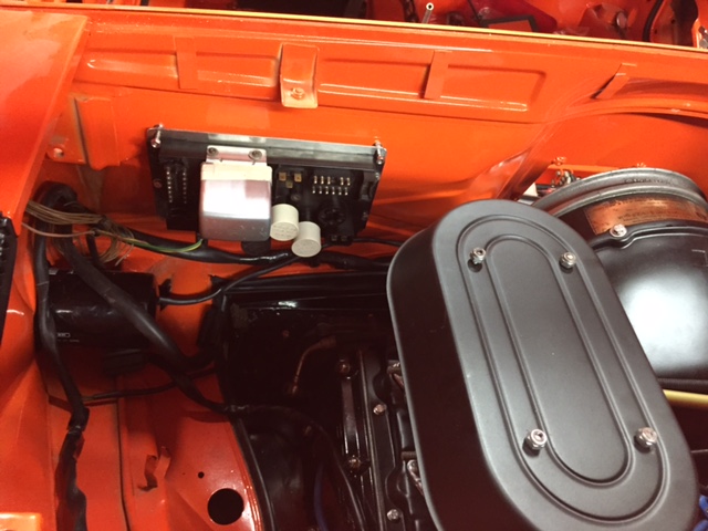 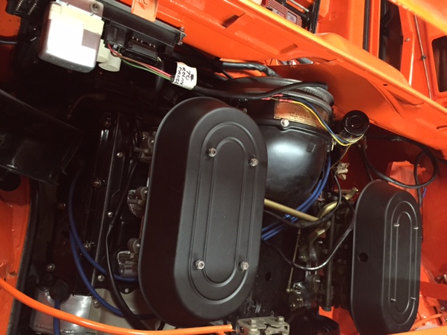 Jeff B |
| Darren C |
 Aug 3 2016, 01:58 PM Aug 3 2016, 01:58 PM
Post
#108
|
|
Member   Group: Members Posts: 392 Joined: 26-December 14 From: Chichester UK Member No.: 18,255 Region Association: England |
I started to mount the relay panel last night and test fit the carburetors. The passenger side rain hat is awfully close to the rear trunk bulkhead. Not sure if this tight clearance is normal or not.   Jeff B Looking good Jeff, but gravity and vibration is NOT your friend with the relays and loom connector plugs if you mount that relay board vertical. That's why the 911 boys hate the OEM boards vertical in their front trunk |
| SixerJ |
 Aug 4 2016, 01:26 AM Aug 4 2016, 01:26 AM
Post
#109
|
|
Member   Group: Members Posts: 448 Joined: 24-June 13 From: UK Member No.: 16,042 Region Association: England |
The KN hats have a fairly large overhang, which is the point I guess. I had a set on the 911 running MFI and removed them as they (only just) rubbed on the the boot lid (I had about 6mm clear when stationary)
When you say tight, how tight? Maybe leave as and apply masking tape or duct tape to the bulkhead and see if it rubs while protecting paint. If it does then you can always give the rain hat a gentle whack for a bit more clearance. Or any opportunity to move the engine and gearbox forward a touch? Keep the vertical board, very factory and not sure about the 911 vertical board comment, I've had the long hood 911 for 20 odd yard and never had an issue with anything shaking loose. Did you make the board? Pictures please |
| jkb944t |
 Aug 4 2016, 05:38 AM Aug 4 2016, 05:38 AM
Post
#110
|
|
Member   Group: Members Posts: 464 Joined: 17-January 05 From: Canton, OH Member No.: 3,459 Region Association: None |
The KN hats have a fairly large overhang, which is the point I guess. I had a set on the 911 running MFI and removed them as they (only just) rubbed on the the boot lid (I had about 6mm clear when stationary) When you say tight, how tight? Maybe leave as and apply masking tape or duct tape to the bulkhead and see if it rubs while protecting paint. If it does then you can always give the rain hat a gentle whack for a bit more clearance. Or any opportunity to move the engine and gearbox forward a touch? Keep the vertical board, very factory and not sure about the 911 vertical board comment, I've had the long hood 911 for 20 odd yard and never had an issue with anything shaking loose. Did you make the board? Pictures please The rain hat is maybe .020 away from the trunk bulkhead if I slide the carbs forward in the bolt holes. I don't think the motor will move forward any more so slightly bending the rain hat probably makes the most sense. I hadn't heard about the vertical relay panel issues either so I was just mounting it the way the other GT cars had it mounted. Maybe I can add some rubber washers to help isolate it from some vibration. Jeff B |
| mb911 |
 Aug 4 2016, 10:17 AM Aug 4 2016, 10:17 AM
Post
#111
|
|
914 Guru      Group: Members Posts: 7,525 Joined: 2-January 09 From: Burlington wi Member No.: 9,892 Region Association: Upper MidWest 
|
Looking good. I like the relay board in that spot.. I may try to do the same thing on my build
|
| Darren C |
 Aug 4 2016, 01:54 PM Aug 4 2016, 01:54 PM
Post
#112
|
|
Member   Group: Members Posts: 392 Joined: 26-December 14 From: Chichester UK Member No.: 18,255 Region Association: England |
A major problem leading to vibration failures results from how a cars control unit's and circuit boards set relative to the vibration motion. The mounting method for control units which include components such as relays can be a source of intermittent problems. An example of this problem is the Bosch CDI unit used on the early Porsche 911s which was mounted on a bracket that transmitted vibrations to the unit resulting in intermittent running problems. A similar intermittent problem occurs with the Porsche cruise control ECU (911/928) the result of its mounting bracket.
Additionally, the larger power control relays, e.g. a 3.2 Porsche 911 DME relay, are affected by the mounting method (cantilever when the board is mounted vertically and the relay sits horizontally) and the resulting vibrations which can cause intermittent starting/running problems. Similar failures occur with early Porsche cabriolet top control units because of the large relays used and the cantilever vertical mounting used for this ECU also. The gravity/vibration comment I made was for the above reasons and in relation to the loom plugs which aren’t great at the best of times and the cantilever effect on them with transmitted vibration and weight of the cables hanging off them. The relays albeit small can be less reliable when mounted on a vertical board. Solid state PCB’s such as those used in ECU are best mounted vertically to avoid vibration cracking of the circuit tracks. Relay and fuse boards are best mounted horizontally to stop cantilever vibration failures. Trust me I’ve seen $Millions of dollars in research into this in the Automotive and Aerospace engineering business. If you want to keep the “trick” look of the vertical relay board, make up a set of straps or clamps to hold in your loom plugs for peace of mind. This is not meant as any kind of criticism, just helpful advice. The car looks great! Regards Darren |
| jkb944t |
 Aug 11 2016, 06:04 AM Aug 11 2016, 06:04 AM
Post
#113
|
|
Member   Group: Members Posts: 464 Joined: 17-January 05 From: Canton, OH Member No.: 3,459 Region Association: None |
This month I ran into a problem with the throttle linkage that had me stumped until I got some much needed help from the forum. The linkage bell crank on the transmission was located in the wrong place by the PO.
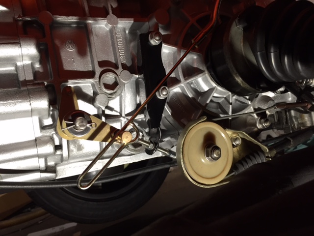 I was able to fabricate a new bracket that is very rigid and it relocated the linkage correctly. 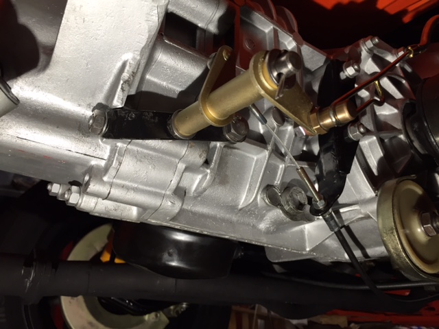 Now I can move onto the next hurdle which is mounting the MSD ignition unit and mount the fuel pump. Jeff B |
| jkb944t |
 Aug 25 2016, 11:03 AM Aug 25 2016, 11:03 AM
Post
#114
|
|
Member   Group: Members Posts: 464 Joined: 17-January 05 From: Canton, OH Member No.: 3,459 Region Association: None |
I finally got to start it up last night! (IMG:style_emoticons/default/piratenanner.gif)
 IMG_6372.MOV ( 1.57mb )
Number of downloads: 239
IMG_6372.MOV ( 1.57mb )
Number of downloads: 239Jeff B |
| Olympic 914 |
 Aug 25 2016, 11:11 AM Aug 25 2016, 11:11 AM
Post
#115
|
   Group: Members Posts: 1,725 Joined: 7-July 11 From: Pittsburgh PA Member No.: 13,287 Region Association: North East States 
|
|
| jkb944t |
 Aug 29 2016, 11:01 AM Aug 29 2016, 11:01 AM
Post
#116
|
|
Member   Group: Members Posts: 464 Joined: 17-January 05 From: Canton, OH Member No.: 3,459 Region Association: None |
I got the front ventilation hoses installed and mounted the new fuel pump up front. I ran new fuel pump wiring from the rear of the car to the front.
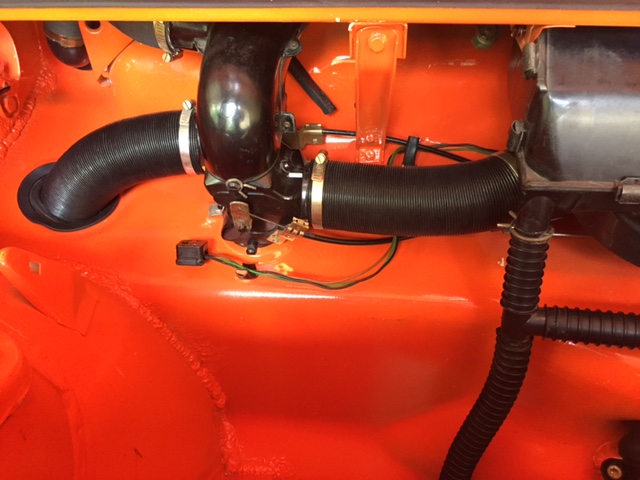 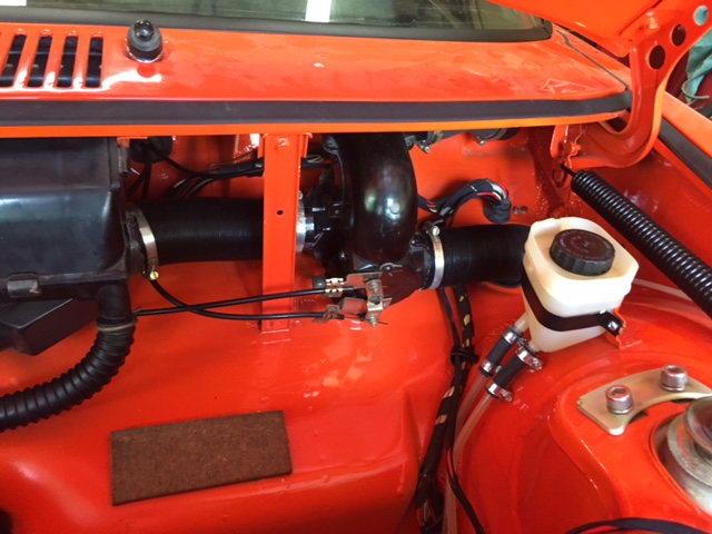 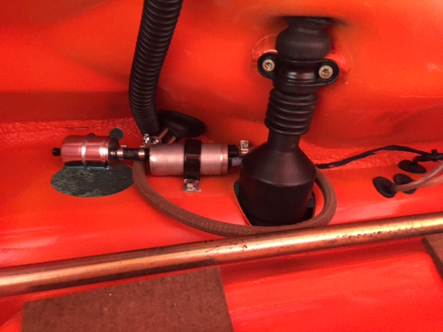 Now I have new SST fuel lines and hoses from the front to the rear of the car for piece of mind. Jeff |
| pete000 |
 Aug 29 2016, 12:04 PM Aug 29 2016, 12:04 PM
Post
#117
|
|
Senior Member    Group: Members Posts: 1,886 Joined: 23-August 10 From: Bradenton Florida Member No.: 12,094 Region Association: South East States |
Looks great.
Looks like access to your fuel pump will be difficult with the tank in place? (IMG:style_emoticons/default/idea.gif) Removing the tank to change a fuel pump is a lot of work IMHO... I assume you are planning on accessing the fuel filter via the access hole? |
| jkb944t |
 Aug 29 2016, 02:48 PM Aug 29 2016, 02:48 PM
Post
#118
|
|
Member   Group: Members Posts: 464 Joined: 17-January 05 From: Canton, OH Member No.: 3,459 Region Association: None |
Looks great. Looks like access to your fuel pump will be difficult with the tank in place? (IMG:style_emoticons/default/idea.gif) Removing the tank to change a fuel pump is a lot of work IMHO... I assume you are planning on accessing the fuel filter via the access hole? Servicing the pre-pump filter should be fairly easy from the access hole. I left enough fuel line on both sides of the pump that by removing the one clamp bolt I should be able to slide the pump out of the access hole too. Hopefully with a brand new fuel pump it shouldn’t be necessary to test this theory. Jeff B |
| jkb944t |
 Sep 9 2016, 05:22 AM Sep 9 2016, 05:22 AM
Post
#119
|
|
Member   Group: Members Posts: 464 Joined: 17-January 05 From: Canton, OH Member No.: 3,459 Region Association: None |
Got the fog lights assembled last night and planning to get the interior in this weekend. Finally getting to the end of the assembly process!
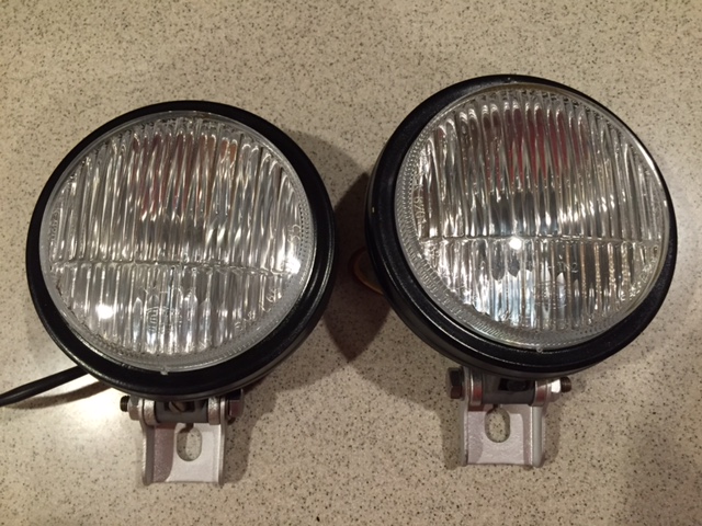 Jeff B |
| jkb944t |
 Sep 13 2016, 06:05 AM Sep 13 2016, 06:05 AM
Post
#120
|
|
Member   Group: Members Posts: 464 Joined: 17-January 05 From: Canton, OH Member No.: 3,459 Region Association: None |
Wanted to document the engine access hole which makes working on the -6 engine a lot easier.
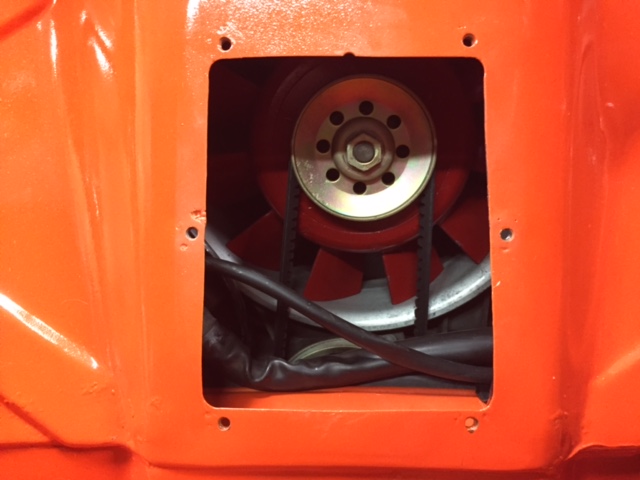 The top of the hole is 5.25 wide and the bottom of the hole is 5.62 wide. It hole is 6.75 high and the bottom edge of the hole is 10.12 up from the top of the center tunnel. 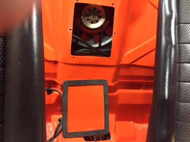 I made a cover that overlaps the hole by about 3/4 of an inch all around and added a closed foam gasket to it. 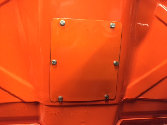 I made some progress on completing the interior this weekend but still lots of details to complete. 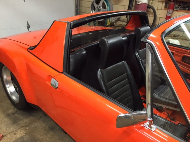 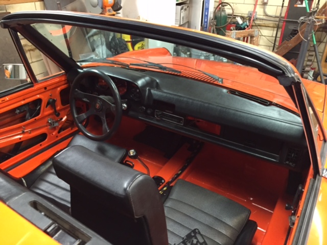 Finally put the engine cover on too. 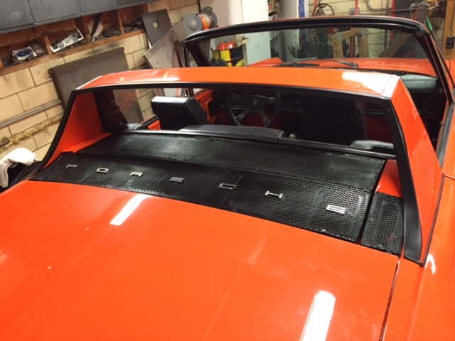 Jeff B |
  |
1 User(s) are reading this topic (1 Guests and 0 Anonymous Users)
0 Members:

|
Lo-Fi Version | Time is now: 3rd April 2025 - 01:12 AM |
Invision Power Board
v9.1.4 © 2025 IPS, Inc.


